Microbial electrolysis cells (MECs) have been explored for various applications, including the removal of industrial pollutants, wastewater treatment chemical synthesis, and biosensing. On the other hand, MEC technology is still in its early stages and faces significant obstacles regarding practical large-scale implementations. MECs are used for energy generation and hydrogen peroxide, methane, hydrogen/biohydrogen production, and pollutant removal. This review aimed to investigate the aforementioned uses in order to better understand the different applications of MECs in the following scenarios: MECs for energy generation and recycling, such as hydrogen, methane, and hydrogen peroxide; contaminant removal, particularly complex organic and inorganic contaminants; and resource recovery. MEC technology was examined in terms of new concepts, configuration optimization, electron transfer pathways in biocathodes, and coupling with other technologies for value-added applications, such as MEC anaerobic digestion, combined MEC–MFC, and others.
1. Introduction
Because of the tremendous growth in the world population and the expansion of industries and mining in recent decades, non-renewable energy supplies have been rapidly depleting [
1]. In the meantime, ample new substances are causing major environmental damage. According to recent studies, surface water contamination in developing countries has resulted in environmental and possible socioeconomic difficulties and substantial public health hazards [
2]. Since the industrial revolution, energy is also a key factor in economic growth. According to estimates, the global energy requirement will rise to 57% more than the current requirements by 2050, assuming a yearly population increase of 1.1% [
3]. Natural oil, gas, and coal are currently some of the main renewable energy sources available in the world, and their widespread use produces numerous inorganic and organic pollutants [
4]. Renewable energy sources are unstable and intermittent during generation, and thus, these valuable electric energy sources are difficult to apply continuously and stably. This also opens the spatial and temporal gaps between the availability of the energy and its consumption by the end users [
5,
6]. On the other hand, water pollution and freshwater shortages are among the most crucial worldwide issues.
Everybody believes that we need to move away from using fossil fuels and toward carbon-free energy sources, but it is not clear how that transition can be done. However, all of these resources are rare, demanding appropriate maintenance techniques. Hydrogen generation via water electrolysis is one of the more efficient ways, with tremendous potential for the change of chemical energy from the electrical energy that may be stored, transmitted, and then used or converted back to electricity on command [
7]. Water electrolysis technologies of various types have been developed, but more progress is needed before they can be integrated into massive and expensive electrical infrastructure [
8]. The kinetics of electrocatalysts, in particular, should be enhanced, along with their cost-effectiveness. Solar-powered electrolysis, for instance, is not yet cost-effective when contrasted with hydrogen synthesis from fossil fuels [
9]. The growing need for fossil fuels and the demand to prevent releasing dangerous elements into the environment have necessitated the development of alternative and sustainable energy sources. In this context, bio-electrochemical systems have gained considerable interest from all around the world.
For well over a decade, scientists have been fascinated by microorganisms that can produce a current and microorganisms that can transmit electrons directly without the use of intermediaries or electron shuttles [
10]. These systems are in different stages of evolution into diverse technologies, such as microbiological fuel cells (MFCs) for the treatment of wastewater and power generation [
11]; MECs, which are devices that use electricity to generate methane or hydrogen gas; and other microbial electrochemical technologies (METs) for desalinating water and producing products, such as hydrogen peroxide (H
2O
2) [
12]. MFCs are devices that oxidize organic and inorganic materials while generating a current using bacteria as catalysts [
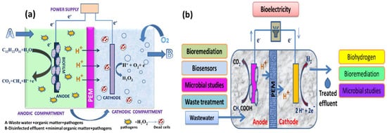
13]. An MEC is a biohydrogen-producing reactor that combines an MFC and electrolysis. An MEC comprises an anode compartment and cathode compartment, a power supply, and a separator. A separator, typically a cation/anion exchange membrane, separates the cathode electrodes. At the anode, microbial strains colonize the electrode surface to form an active biofilm by producing electrons, protons, and carbon dioxide via biological oxidation using organic materials, such as sewage sludge, wastewater, or sugar solutions, as their energy source. The electrons produced at the anode travel through an external circuit and the solution to the cathode, where they merge with protons to form hydrogen (a schematic representation is given in
Figure 1a,b) [
14,
15,
16]. The protons are transferred from the anode to the cathode through the proton exchange membrane (PEM). In the case of the anion exchange membrane (AEM), the OH
− ions produced from the cathodic oxygen reduction reaction are transferred to the anode via the AEM.
Figure 1. (a) Anodic effluent containing residual organic matter and pathogens recalculated into the cathodic chamber for disinfection through H2O2 and (b) various important applications of MECs.
Meanwhile, CO
2 will react with electrons and protons to produce methane and water. The MEC, in particular, has a lot of potential to become a green and sustainable energy source. Unfortunately, because an MEC’s cathode potential is more significant than its anode potential, the electrons generated cannot easily flow to the cathode. As a result, a low-power source of 0.2–0.8 V is required to activate electron migration [
17].
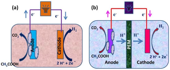
An MEC is used to produce hydrogen peroxide, methane, and hydrogen/biohydrogen to remove pollutants (
Figure 2) [
18]. This review investigated the earlier uses to better comprehend MEC’s uniqueness. Problems and prospects were also examined to assist academics in understanding the most recent developments in MEC technology and applications. Furthermore, the future scope of research is considered in light of numerous issues related to the system’s representativeness and flexibility, which could lead to a cost-effective and potentially useful technology.
Figure 2. (a) Construction of a single-chambered MEC and (b) a schematic representation of a dual-chambered MEC.
2. MFC and MEC
MFCs are devices that use microorganisms as catalysts to oxidize organic and inorganic substances and generate electricity, whereas an MEC combines an MFC and electrolysis to create biohydrogen. In an MEC, however, an external voltage must be provided to overcome the thermodynamic hindrance. MFCs have provided a long-term solution for generating bioelectricity from carbon [
19]. In an MFC, organic substrates are transformed into hydrogen through the biohydrogen production process. Microorganisms aid in the decomposition of the organic substrate at the anode, which leads to the generation of electrons and protons. Electrons are transmitted from the anode to the cathode using an electrical circuit. Through a series of metabolic reactions, the exoelectrogens in the anode chamber catalyze the oxidation of organic molecules to carbon dioxide [
20]. These responses send electrons through an outside circuit, where they combine with protons traveling through the proton trade film to form hydrogen on the cathode. Because organic material is used as a proton source for hydrogen generation instead of water, the process is called biocatalyzed electrolysis. A cathode, an anode, and an ion-selecting membrane separate the two electrodes in both MFCs and MECs. Biocathodes are used in specific situations. The majority of MFCs are used to generate energy. By providing an anaerobic environment to both the anode and cathode compartments, MFCs can also be used to produce hydrogen. Because the efficiency of hydrogen production from an MFC is low, MECs have been designed [
21]. MECs, like MFCs, have electrochemically active bacteria on the anode surface that help to convert organic matter into protons, electrons, and carbon dioxide. The electrons created are then transmitted to the cathode, resulting in hydrogen generation. The two types of membranes are commonly used for reaction avoidance between produced hydrogen and oxygen. They are cation exchange membranes and anion exchange membranes. An anion exchange membrane is more typically used for hydrogen generation because it has a lower resistance to ion transport through the membrane due to reduced internal resistance [
22]. As a result, the use of an MEC accelerates the degradation of the substrate, resulting in hydrogen production.
MECs are similar to MFCs in that they have two chambers connected by an ion-exchange membrane. Several various combinations of MECs have been modified throughout the decades to increase efficiency and are discussed below. A fundamental H-type cell with gas collection pieces coupled to a cathode compartment was used in prior designs. Subsequently, significant improvements were made to create dual-compartmental MECs that were simple to operate. Following a comprehensive evaluation of numerous configurations, a single-compartmental MEC exhibited larger fabrication/recovery rates and current densities than a dual-compartment MEC. As a result, a lot of time and effort has been put into fine-tuning this grouping for usage in scale-up investigations. Several sorts of reactor upgrades were put together based on the results: single-chambered, dual-chambered, combined, and many others.
2.1. Single-Chambered MECs
The initial configuration used a glass container with an overall capacity of 50 mL. The subsequent setup applied borosilicate glass vials with a total volume of 10 mL; the cells generally contained a mixed culture or pure culture. To keep the cathode and anode, which measured 4 × 5 cm2 and 3.5 × 4 cm2, 2 cm apart, plastic screws were utilized. The anode was constructed of type A carbon, while the cathode was type B carbon with platinum. As illustrated in Figure 2a, single-chambered MECs lack a membrane. Since hydrogen is moderately insoluble in water, when production rates are greater, the microbial conversion of methane from hydrogen is slowed. In membrane-less MECs, energy losses are reduced, and the energy recovery phase is effective.
2.2. Dual-Chambered MECs
The anodic and cathodic chambers of dual-chambered MECs are divided by a membrane, as seen in Figure 2b. Due to their complex structures and high volumes with greater internal resistance, dual-compartmental MECs are difficult to scale up. The application of a membrane serves two purposes. It shortens the transition from the anode compartment to the cathode compartment, preventing short circuits and preserving the quality of the cathode-side product. The proton exchange membrane (PEM) is the most commonly used one because it is designed to allow only freely available protons to pass through while using –SO3-type functional groups. Secondary membranes, including anion-exchange membranes, such as bipolar membranes, AMI7001, and charge-mosaic membranes, have been studied in MECs, along with regular membranes.
2.3. Proton Exchange Membranes
The primary role of a PEM in an MEC-based technique is to separate reactants and transfer protons from the anode to the cathode. A PEM is a semipermeable membrane formed of ionomers that is developed to transfer protons while being impermeable to gases, such as oxygen and hydrogen. Polymeric membranes or mixed membranes, wherein additional materials are embedded in a polymer matrix, can be used to construct PEMs. Nafion is the most popular PEM material, with a hydrophobic Teflon-like backbone (-CF
2-CF
2-) and hydrophilic side chains terminating with ion-conducting sulfonic acid groups (-SO
3-H). However, the Nafion membrane is costly, prone to fuel and gas crossovers, and has limited proton selectivity. By combining with the gases produced in the anode compartment, an MEC decreases hydrogen purity in the cathode compartment. As a result, a variety of new membrane types have been developed that use different proton (or ion) conductors. Therefore, for commercial applications of those technologies, it is important to develop alternative membranes to the expensive Nafion. The alternative choices to Nafion are considered based on a few previous works reported by researchers [
23,
24]. A nanofiber-reinforced composite proton exchange membrane (NFR–PEM) based on sulfonated polyether ether ketone (SPEEK) as a proton conductor was prepared and studied for microbial electrolysis cells (MECs) [
23]. A sulfonated poly(arylene ether sulfone) (SPAES)/polyimide nanofiber (PIN) composite proton exchange membrane was developed for use in microbial electrolysis cells (MECs), where diverse cations that compete with protons coexist in high concentrations [
24].
3. Applications of MEC
3.1. Electrosynthesis of Compounds
3.1.1. Hydrogen Peroxide
MFCs and MECs can manufacture H
2O
2 from wastewater via electron reduction of O
2 in the cathodic compartment, overcoming some of the current obstacles in H
2O
2 synthesis [
25,
26]. However, MFCs have a lower rate of H
2O
2 production, which limits their use in wastewater treatment on a large scale [
27]. To overcome this challenge, many researchers have worked on MECs to accelerate production by providing external power. Compared to current technologies, MECs’ H
2O
2 generation is favorable since the process can treat wastewater while also producing H
2O
2 [
28]. Unlike the other approach, this one does not involve using any harmful ingredients or catalysts. Furthermore, the process can be run with little or no energy input, making it compatible with a sustainable future.
An MFC can effectively remove organic matter from wastewater; nevertheless, tertiary treatment is required to remove the remaining contaminants, such as residual organic matter, pathogens, and xenobiotics [
29]. By delivering secondary and tertiary treatments in anodic and cathodic chambers, an MEC can satisfy both requirements. Once the majority of the organic matter is removed from the effluent in the anodic compartment, it leads to a cathodic compartment for H
2O
2 production [
30]. The H
2O
2 produced in an MEC’s cathodic chamber can also remove dyes and other xenobiotic chemicals, providing comprehensive wastewater treatment. Both treatment steps can be provided in a single reactor with such a modular arrangement, lowering both operational and capital expenses. As a result, an MEC is more efficient than an MFC in terms of the H
2O
2 generation rate [
31]. Over the past decade, researchers have adapted many modifications to increase the production of H
2O
2. Junyoung et al. looked into cathode potential and O
2 supply procedures to enhance the synthesis of H
2O
2. Their study found that decreasing the current density for passive O
2 diffusion to the cathode increased H
2O
2 conversion efficiency by 65%. The MEC was made up of an acetate medium gas diffusion cathode and wastewater. They obtained 141 mg H
2O
2/Lh using an acetate medium and 6 mg H
2O
2/Lh using wastewater [
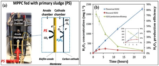
32]. Dongwon et al. created an anaerobic energy conversion method for converting primary sludge at the anode using a dual-chambered, flat-plate, energy-efficient microbial peroxide-producing cell (see
Figure 3a). H
2O
2 concentrations and H
2O
2 production efficiency during batch cathode operation in the MPPC are shown in
Figure 3b. By 6 h, the H
2O
2 content had risen to 230 mg L
−1, but by 24 h, it had dropped to 121 mg L
−1. Depending on the electrical current generated at the anode, the predicted H
2O
2 produced rose linearly up to 2300 mg L
−1, showing that the PPE decreased over time, from 72% at 1.5 h to 5% at 24 h. [
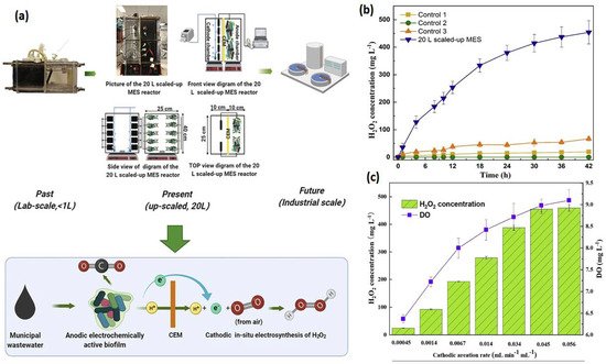
33]. Rusen et al. created a dual-chambered 20 L MEC for in situ and proficient H
2O
2 electrosynthesis, as represented in
Figure 4. Under acidic or alkaline circumstances, freshly generated H
2O
2 would later undergo reduction to give H
2O and OH-, and H
2O
2 would decompose. As a result, more H
2O
2 would be decomposed with a longer running time. In 42 h, the H
2O
2 concentration at the cathode grew monotonically as the aeration rate was increased, indicating that the preferred aeration rate range had no detrimental influence on H
2O
2 manufacture at the cathode. After 42 h, a 0.6 V input voltage resulted in a greater rate of H
2O
2 production of 10.82 mg/Lh and a collective H
2O
2 concentration of 454.44 mg/L. In conclusion, the earlier studies demonstrated the viability of using a graphite plate as the cathode in a scaled-up ORR to create H
2O
2 [
34]. Wang et al. modified carbon nanotubes by doping them with fluorine and used the same method to fabricate the gas diffusion electrode. This modification improves H
2O
2 selectivity and produced approximately 47.6 mg/L [
35,
36].
Table 1 gives the details of different studies performed on hydrogen production.
Figure 3. Results of a microbial peroxide producing cell’s cathode batch operation (MPPC). (
a) Theoretical and measured H
2O
2 concentrations that rely on a 100% transition from cumulative coulombs and a detection method, and H
2O
2 productivity improvement (PPE) (N = 3 measurements). The inset shows the first six hours of operation in the MPPC. (
b) Catholyte pH and alkalinity over a 24 h batch run. The results of a cathode batch operation of a microbial peroxide producing cell are given. (Reprinted with permission from [
33]. Copyright 2019, American Chemical Society.)
Figure 4. (
a) Verification of this 20 L scaled-up MES reactor’s feasibility for H
2O
2 generation. (
b) Input and operating conditions: the electrolyte nature and concentration were 50 mM Na
2SO
4, the voltage was 0.6 V, the cathode aeration velocity was 0.045 mL min
−1 mL
−1, and the original catholyte pH was 3. There was no cathodic aeration in control 1. The circuit for control 2 was broken. Control 3: no voltage input. H
2O
2 production was affected by cathodic aeration velocity. Input voltage of 0.6 V, initial catholyte pH of 3, and electrolyte nature and concentration of 50 mM Na
2SO
4 were used as operating conditions [
34]. (
c) Effect of cathodic aeration velocity on H
2O
2 production. Operating conditions: input voltage of 0.6 V, initial catholyte pH of 3, and electrolyte nature and concentration of 50 mM Na
2SO
4, respectively. (Reprinted with permission from [
34]. Copyright 2021, Elsevier.)
Table 1. The details of different studies performed on hydrogen production.
| Sl. No |
Types of Cathode Materials |
H2O2 Production Rate (mg/Lh) |
Operating Conditions |
Energy Consumption (kWh/Kg H2O2) |
Reactor Volume (mL) |
Ref. |
| 1 |
Graphite hybrid air cathode and carbon black |
3.3 |
pH was 7, NaCl concentration was 50 mM, operated voltage was 0.6 V, and cathodic aeration rate was 1500 mL/min |
56 |
42 |
[37] |
| 2 |
Gas diffusion electrode |
4.2 |
pH was 7, NaCl concentration was 50 mM, and operating voltage was 0.9 V |
1.8 |
18.8 |
[38] |
| 3 |
Vulcan carbon-coated gas diffusion electrode |
8.8 |
pH was 7, NaCl concentration was 200 mM, operating voltage was 0.31 V, and cathodic aeration rate was 20 mL/min |
1.1 |
218 |
[39] |
| 4 |
MEC (electro-chemically tailored graphite particle) |
88.2 |
pH was 7, NaSO4 concentration was 50 mM, and applied voltage was 0.4 V |
0.66 |
96 |
[40] |
| 5 |
Carbon black/graphite hybrid GDE |
205.4 |
- |
0.6 |
150 |
[41] |
| 6 |
Carbon cloth |
1300 |
- |
0.93 |
85 |
[42] |
| 7 |
Carbon felt |
340 |
- |
2.5 |
41 |
[43] |
MECs have emerged as a viable technology for eco-friendly H2O2 generation. There are several fundamental and applied characteristics of H2O2 production in MECs that focus on the significance of a variety of operational parameters and potential environmental uses of generated H2O2. A literature search revealed that lab-scale MECs successfully created appropriate H2O2 concentrations for various water treatment systems. Despite its promise, there are still several obstacles that still need to be resolved. Initially, the electrolyte was introduced into this study with the intention of increasing the system current and, thus, H2O2 production, which would increase production costs. Furthermore, the cathodic oxygen use rate was low, as evidenced by the cathodic aeration delivered by the pump, which accounts for the majority of the total energy usage. However, if the reactor architecture is optimized and novel electrode materials with improved oxygen mass transfer efficiency are developed, this issue can be fixed in the future.
3.2. Wastewater Treatment
Wastewater is increasingly regarded as a “misplaced resource” that may be used to create quality products and energy. In the case of wastewaters, proper management frequently necessitates energy treatment, adding a significant impact on climate change. Because of their stability and diversity, biological anaerobic treatment methods have become the go-to option for reclaiming most of this energy. MECs have several advantages over MFCs. Nonetheless, the resultant product by an MEC has a significant impact on its performance (hydrogen, methane, ethanol, hydrogen peroxide, etc.), and its tremendous energy production has led to speculation that it would be the future’s power source. In combination with sulfate-reducing bacteria, an MEC was developed by Kai Wang et al. and was utilized to reduce sulfate-rich wastewater that lacked electron donors. The results showed that it might produce a powerful synergy when SRB is combined with an applied current.
The maximum sulfate removal of 14.9% greater than the control reactor was achieved with a 1.5 mA applied current [
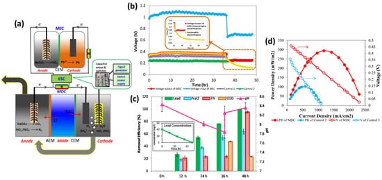
64]. Yan Li et al. achieved instantaneous elimination of nitrogen in wastewaters, metal in industrial effluents, and salinity in saltwater using a combined microbial desalination cell (MDC)–MEC system. The cathode solution was transferred to the MDC anode when the ammonium content fell below 2 mg L
−1 during aerobic nitrification to improve total nitrogen percentage removal so that the accumulated nitrate and nitrite might be reduced via heterotrophic denitrification in an anoxic anode with a carbon supply, as shown in
Figure 8a. A test was conducted using wastewater alone without ammonium injection in the cathode to further examine the effect of nitrogen removal on the power output of the MDC handling nitrogen-rich wastewater. During the first 36 h, the voltage output of the MDC was slightly more significant than that of the test, suggesting that ammonium in wastewater had an impact on the voltage output, likely leading to an increase in conductivity to lower internal resistance. MDC displayed removal effectiveness of 62.9% for 48 h, greater than conventional reverse osmosis but significantly lower than RO, showing that MDC could successfully extract salt but required a longer retention period (see
Figure 8b). Nitrification oxidized greater than 95.1% of the nitrogen in batch testing, resulting in a complete nitrogen elimination rate of 4.07 mg L
−1 h
−1.
Figure 8. (
a) The integrated MDC–MEC system diagram (
b) Voltage changes of MDC output and MEC input through ESC. (Inserted figure: Voltage output of autotrophic denitrification and heterotrophic denitrification) (
c) Removal efficiencies of NaCl, total nitrogen, and COD in the MDC and lead (II) in the MEC and pH variation at different operational periods (Inserted figure: lead (II) concentration over time) (
d) Power densities and voltages of the MDC and Control 2 at the Rext. of 14-4580 Ω (V: voltage; PD: power density). (Reprinted with permission from [
65]. Copyright 2017, Elsevier.)
This entry is adapted from the peer-reviewed paper 10.3390/en15072611