1. Perovskite Tandem Photovoltaics
Perovskite tandem PVs have been suggested as a method to improve the overall performance, stability, and lifetime of perovskite PVs. A perovskite tandem PV usually consist of a cell—either silicon, perovskite, or copper indium gallium selenide (CIGS)—overlaid by a perovskite PV [
126], to increase the efficiencies beyond a single junction limit [
127], without adding a substantial cost during production [
128,
129]. Typical single-junction PV cells do not make use of 67% of the solar energy they receive, because of the weak absorbance capabilities of the semiconductors. Semiconductors can only absorb photons with energy is above their bandgap energy (E
g) and they generate energy equal to E
g, where the rest of the energy are lost through thermalization as heat. This will severely affect the PCE of a PV because it corresponds to the V
oc and J
sc of the PVs. As one of solutions, tandem photovoltaics can address this problem [
130].
Tandem PVs use stacks of materials with different bandgaps, where materials with larger bandgaps are put at the top of a cell and those with small bandgaps are at the bottom. High-energy photons are absorbed by the upper materials, while low-energy photons are not lost, in this case, but rather are absorbed by the lower stack materials, making use of most of the incident energy. One of the most known structures of tandem cells is the double-junction tandem device. They have two different configurations: two-terminal (2-T) and four-terminal (4-T) tandem, according to the stacking method used [
130].
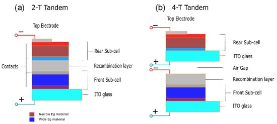
The 2-T tandem cells are synthesized by stacking a transparent front electrode, with a front cell and an opaque rear electrode, with the rear cell being one substrate where an interconnection layer (ICL) separates them, as shown in
Figure 7a. The recombination of the photogenerated carriers from either sub-cell takes place in the ICL. On the other hand, 4-T tandem cells are made of two separate devices with two separate electrodes, linked together through a dichromatic mirror, as shown in
Figure 7b. However, due to the additional electrodes, the optical loss will result in a more expensive cost compared to 2-T tandem PVs. Moreover, 2-T tandem PVs are cheaper to fabricate, though it is harder to fabricate 2-T or monolithic tandem PVs compared to 4-T tandem PVs for general applications [
130].
Figure 7. Schematic diagram of (a) 2-T and (b) 4-T tandem perovskite.
Based on the values shown in
Table 2, Voc, Jsc, and FF have similar in values with the 4-T Si/MAPbI
3 configuration [
131,
132,
133] and the values of Voc, Jsc, and FF in these works are about 1.1 V, 21 mA cm
−2, and 75–80%, respectively.
Table 2. Some reports of perovskite tandem PVs. Voc, Jsc, and FF are open-circuit voltage, short-circuit current density, and fill factor, respectively.
| Type |
Tandem |
Perovskite Material |
Voc (V) |
Jsc (mA cm−2) |
FF (%) |
Size (cm2) |
PCE (%) |
Ref. |
| 4-T |
Si |
MAPbI3 |
1.08 |
20.6 |
74.1 |
0.075 |
23.0 |
[131] |
| 4-T |
Si |
MAPbI3 |
1.098 |
21.0 |
74.1 |
1.10 |
26.7 |
[132] |
| 4-T |
Si |
MAPbI3 |
1.156 |
19.8 |
79.9 |
1.00 |
27.0 |
[133] |
| 2-T |
Si |
MAPbI3 |
1.69 |
15.9 |
77.6 |
0.17 |
21.2 |
[134] |
| 2-T |
Si |
Cs0.05(FA0.77MA0.23)0.95Pb(I0.77Br0.23)3 |
1.87 |
19.37 |
79.9 |
1.06 |
29.3 |
[4] |
| 2-T |
Si |
Cs0.05(MA0.17FA0.83)0.95Pb(I0.83Br0.17)3 |
1.792 |
19.02 |
74.6 |
1.088 |
25.2 |
[135] |
| 2-T |
Si |
Cs0.15(MA0.17FA0.83)0.85Pb(I0.7Br0.3)3 |
1.80 |
17.8 |
79.4 |
~1.00 |
25.4 |
[136] |
| 4-T |
CIGS |
Cs0.09FA0.77MA0.14Pb(I0.86Br0.14)3 |
1.77 |
17.3 |
73.1 |
0.04 |
22.4 |
[137] |
| 4-T |
CIGS |
Cs0.05(MA0.17FA0.83)Pb1.1(I0.83Br0.17)3 |
1.59 |
18.0 |
75.7 |
0.78 |
21.6 |
[138] |
| 2-T |
CIGS |
Cs0.05(MA0.17FA0.83)0.95Pb(I0.83Br0.17)3 |
1.68 |
19.2 |
71.9 |
1.03 |
23.3 |
[33] |
This occurs similarly in the 4-T CIGS/Cs
0.05(MA
0.17FA
0.83)Pb
1.1(I
0.83Br
0.17)
3 configuration [
138] and the 2-T CIGS/Cs
0.05(MA
0.17FA
0.83)
0.95Pb(I
0.83Br
0.17)
3 configuration [
33], since these works obtained similar values for Voc, Jsc, and FF of about 1.6–1.8 V, 17.0–19.2 mA cm
−2, and 72.0–75.7%, respectively.
In comparison to the PCE values in
Table 2, the 2-T configurations of CIGS/Cs
0.05(MA
0.17FA
0.83)
0.95Pb(I
0.83Br
0.17)
3 [
33,
138] are better by 1.08-fold compared to those of the 4-T configurations. The 4-T configurations experience optical loss, which is found in the encapsulation and absorption in the transparent conductive electrode [
139], which affects the PCE. The 2-T configurations experience series resistance loss in the large-area modules [
140].
Further analysis is required to determine the increase in the PCE of the devices through development and improvements using tandem technologies. The configurations in
Table 2 for tandem PVs refer to the materials in
Table 1. The best performing PCE is from the Cs
0.05(MA
0.17FA
0.83)
(0.95)Pb(I
0.83Br
0.17)
3 configuration in
Table 1, and shows a PCE of 18.6% [
81]; the best performing PCE from the 2-T Si/Cs
0.05(FA
0.77MA
0.23)
0.95Pb(I
0.77Br
0.23)
3 configuration has a PCE of 29.3% [
4] with an improvement achieved through tandem technologies using silicon and also through the use of an appropriate carbazole-based layer to efficiently extract the holes. Silicon was used as the bottom cell of the tandem since it has the properties of absorbing solar radiation from the near infrared region of the absorption spectrum. There is also another development in tandem PVs between Cs
0.05(MA
0.17FA
0.83)
0.95Pb(I
0.83Br
0.17)
3 perovskite and CIGS, and the PCE value of the Cs
0.05(MA
0.17FA
0.83)
0.95Pb(I
0.83Br
0.17)
3 tandem [
33] increases by 1.25-fold compared to that of the intrinsic one [
67].
The CIGS allows for a tunable bandgap, and it varies based on the temperature. A tunable bandgap was obtained from 1.1 to 2.3 eV by interchanging the cations, metals, and halides. These allow for the tandem PV to absorb photons that have an energy above the bandgap, so a higher bandgap will require a higher energy for the absorption spectrum. The best configurations for perovskite tandem PVs came from silicon and CIGS. In fact, another perovskite–perovskite tandem PV has been recorded, with a high PCE of 24.4% [
141] and there are few reports presently beating this record. Therefore, the best reported tandem perovskite photovoltaic belongs to the 2-T Si/Cs
0.05(FA
0.77MA
0.23)
0.95Pb(I
0.77Br
0.23)
3 configuration with a PCE of 29.3% [
4].
For further commercialization of perovskite PVs, large area modules should be developed since the previous studies were conducted for a small area (1 cm2). This development needs to be carried out to determine if there is any improvement in the crystal grain structure and PCE value when the module size is increased.
2. Large Scale Modules
Several issues need to be addressed for further perovskite PV commercialization: (i) a thin-film deposition method that is scalable and reproducible; (ii) high stability and long lifetime; and (iii) low or less toxic materials for large-area devices.
The rapid increment in PCE performance for perovskite PV has developed at a quick pace compared to other solar technologies. However, several high PCE values have been obtained with very small areas (~1.0 cm
2). To fabricate a large area with a high-quality perovskite (good uniformity and few structural defects), several deposition methods have been developed, such as spin-coating, slot-die coating, doctor blade, and vacuum deposition. In 2015, Chen et al. [
142] fabricated perovskite using one-step spin-coating with an active area of 1.02 cm
2 and obtained a PCE of 15%. In 2016, Qiu et al. [
143] fabricated a large-area perovskite with an active area of 1 cm
2 and obtained a PCE of 13.6%.
While spin-coating is widely used in the deposition of small-area thin films in laboratories, it might not be suitable for industrial large-area fabrications. Spin-coated films are not uniform throughout the area [
144], require a large amount of solution mixture of materials, and there is significant wasted solvent, which increases the cost of fabrication. Its performance also reduced due to the increase in series resistance and the decrease in film quality [
145,
146]. As in the case of Hossain et al. [
147], since spin-coating is not suitable for the fabrication of perovskite solar cell on a silicon solar cell, so some methods have to be replaced by PVD or CVD.
In 2018, Zheng et al. [
148] were able to achieve 21.8% PCE using CVD on a 16 cm
2 monolithic (FAPbI
3)
0.83(MAPbBr
3)
0.17 perovskite–silicon tandem PVs. The final product of the PVs has an enhanced V
oc with a J
sc that ranged from 15.6 to 16.2 mA/cm
2 and an FF of 78%. The supporting information regarding further improvements that could be achieved for this device would be the spiro-OMeTAD stack being replaced with a high refractive index inorganic hole transport layer to eliminate unnecessary wavelength absorptions. To improve it for commercial use in larger area of 6″ × 6″, the PDMS layer can be replaced with thin glass and the spin-coating process can be replaced with something less expensive, such as the doctor blade or spray-coating methods, which will be discussed in further works.
After conducting their previous work, in 2019, Zheng et al. [
149] showed another improvement that increased the PCE value. They decided to use micron green-emitting (Ba,Sr)
2SiO
4:Eu
2+ phosphor—a cheap material that is commercially available and is mostly used in light-emitting diodes—as an antireflective down shifting material on PDMS that acts as the hydrophobic layer of the silicon–perovskite tandem PVs with an area of 4 cm
2, which achieved a PCE of 23%. SEM images of the (Ba,Sr)
2SiO
4:Eu
2+ sample on PDMS showed a high-quality crystal size of about 10–20 μm. Moreover, the results of energy-dispersive X-ray spectroscopy (EDX), not only confirmed the homogeneous distributions of Sr, Ba, Si, and O within the specimen, but were also able to detect the Eu content.
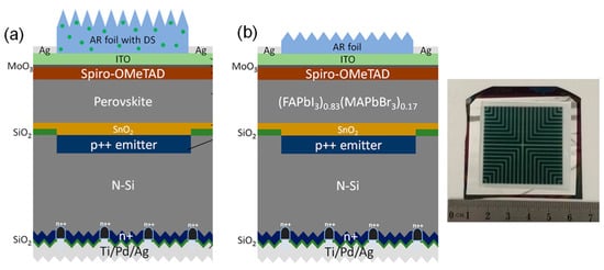
Figure 8 shows schematic diagrams of the (a) previous and (b) current large-scale modules of perovskite photovoltaics.
Figure 8. (
a) Schematic of perovskite–silicon tandem homojunction photovoltaic with downshifting AR PDMS layer. From Ref. [
149]. Copyright 2019 ACS Energy Letters. (
b) Schematic of monolithic (FAPbI
3)
0.83(MAPbBr
3)
0.17 perovskite/rear-textured-homo-junction-silicon tandem photovoltaics. Reproduced with permission from Ref. [
148]. Copyright 2018 ACS Energy Letters.
After further investigation, with a higher concentration of (Ba,Sr)2SiO4:Eu2+ phosphor on top of the perovskite–silicon PV, with initial conditions of Jsc of 14.1 mA/cm2, Voc of 1.73 V, FF of 82%, and a PCE of 20.1%, the result shows that, while the open-circuit voltage remains unchanged or at a constant level, there was an improvement in Jsc that was caused by the increased broad absorption of the cell with a reduced front reflection and increased light trapping. Eventually the best choice was obtained and had an area of 4 cm2 with conditions of Jsc of 16.4 mA/cm2, Voc of 1.73 V, FF of 81%, and a PCE of 23%.
Although works on monolithic perovskite–silicon tandem PVs showed progress in terms of PCE values (about 22–23%), there are several issues that need to be solved for further large-scale fabrication. These issues include stability improvements, the degradation rate, commercialization costs, and the use of environmentally friendly materials.
3. Improvements to Perovskite Material and Its Tandem Structures
A recent investigation, conducted by Green et al. [
1] on perovskite–silicon tandem PVs, states that a high PCE value of 29.15% had been achieved with an area of 1.060 cm
2. Though it is a small area, in the future, people will continue to develop perovskite–silicon tandem photovoltaics, which will progress further so that it is possible to achieve 4 cm
2 perovskite–silicon tandem photovoltaic with an efficiency of 29.15%, if there is a breakthrough on how to further increase the broad absorption of a cell with reduced reflection but while increase the light trapping.
Furthermore, since it is difficult to deposit a large area of continuous perovskite film using the previously described traditional methods, other methods should be improved to prepare high-quality and large-area perovskite PVs for commercial production in the future. Moreover, from the perspective of green energy, the Pb employed in perovskite PVs is highly toxic, which will hinder the industrial promotion and development of perovskite PVs. Therefore, it is necessary to find a low-toxicity or non-toxic material to replace Pb in the future [
96].
Realistically, the halide of Pb is 10 times more dangerous than the Pb that already exists on Earth [
150,
151,
152,
153]. Several lines of research indicate that contamination due to leaks of lead ions into soil and water resources is a permanent affliction and generates harmful effects on humans, animals, and plant survivability [
154,
155,
156,
157,
158,
159,
160,
161,
162,
163]. To decrease and reduce its toxicity level, Pb-free [
164,
165,
166] (or at the very least less Pb content) perovskite–silicon PVs have been researched using a safer option by mixing chalcogen and halogen anions [
167] or using tin or (Sn)-based perovskite PVs [
168,
169,
170]. Recently, it was determined that there is an all-perovskite Pb–Sn tandem photovoltaic with a PCE of 26.4% [
171], showing a value that potentially exceeds that of the best-performing single-junction perovskite solar cells, which are capable of retaining more than 90% of their initial performance after 600 h of operation at maximum power under one-sun illumination under ambient conditions. Recent research [
172], developed a low-cost device made of sulfonic acid-based lead-adsorbing resin, which freezes lead ions into a scaffold and prevents their leakage when the perovskites are exposed to rainfall. This new device does not affect efficiency or scaling and the structure can be scaled up to 60.8 cm
2.
However, Sn-based perovskite PVs have lower efficiencies and faster degradation than Pb-based perovskite PVs due to their phase fluctuations and they easily oxidize from Sn
2+ to Sn
4+. In the case of Sn-based perovskite PVs being unable to breach the efficiency limit of Pb-based perovskite PVs, new approaches had been created to prevent Pb leakage in perovskite PVs by trapping Pb with cation-exchange resins that are abundant in Ca
2+ and Mg
2+ [
173].
In addition, the cost barrier for perovskite–silicon cells was identified as being due to expensive organic charge transport materials, such as spiro-OMeTAD, PTAA, and PC
60BM [
174,
175,
176,
177]. The cost of organic charge transport, especially for one with a higher quality that can yield a better performance, is very expensive due to the intricate nature of the fabrication steps, in addition to the additional costs that might be derived from better or higher purity in terms of the formation of crystal grains. As an alternative to using organic charge transport materials, inorganic charge transport materials, such as NiO, CuSCN, SnO
2, and Nb
2O
5, which are much cheaper in comparison to organic charge transport materials, have been successfully developed for some perovskite PVs [
101,
178,
179,
180].
Further improvements concern the degradation of the perovskite PVs. PVs are always exposed to various degradation sources, such as humidity, oxygen, heat, and ultraviolet light. To ensure the lifetime of perovskite–silicon tandem PVs, their stability needs to be tested and improved against degradation. Among perovskite PVs, methyl ammonium lead triiodide is easily degraded by humidity and heat, in comparison to perovskite PVs that are based on FAPbI
3 [
60] or CsPbI
3 [
181], which proved to have a higher resistance to thermal decomposition—which can be solved by mixing the cations and the halogen anions, which improves the thermal and crystal structure stability. As an example of mixing halide anions, bromide-based perovskite PVs show better resistance to degradation under humidity and heat when compared to iodide-based perovskite PVs as they developed a 2D or 3D hetero-structure in the perovskite PVs [
182,
183,
184].
It is also suggested that organic charge transport materials, such as spiro-OMeTAD, PTAA, and PC
60BM, are easily disintegrated by humidity and oxygen, so they require a higher level of encapsulation to prevent the elements from disintegrating the organic charge transport materials. An alternative solution would be to use inorganic charge transport materials, which are beneficial in terms of their stability due to their basic properties. In addition, a densely formed inorganic layer can act as a diffusion barrier to prevent organics or iodine species escaping from the lattice and reacting with the top metal electrode [
185,
186]. It has been reported in the literature that a semi-transparent perovskite PV with a dense charge transport layer and a transparent electrode endured through thermal cycling, damp heat, and UV stress tests [
185,
186,
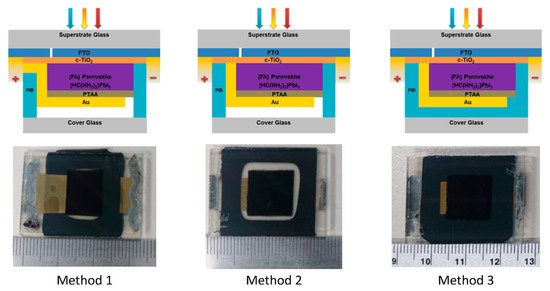
187]. Moreover, low-temperature, glass–glass encapsulation techniques, using high-performance polyisobutylene (PIB) on planar perovskite solar cells, have been reported using three different electrical configurations and methods are as shown in
Figure 9 [
188]. In method 1, PIB is put on the top of a thin gold film that acts as a positive electrical feedthrough for the cell. In methods 2 and 3, the FTO layer provides the electrical feedthroughs. It is worth noting that the PIB in methods 1 and 2 plays the role of an edge seal, but it blankets the entire area under the glass in method 3.
Figure 9. Cross-sectional schematics with the photographs of perovskite solar cells encapsulated by three different methods [
188]. From Ref. [
188]. Copyright 2017 ACS Applied Materials and Interfaces.
Lead-free PVs are also being investigated as potential improvements to PVs [
157,
164], as these same materials were investigated as scintillators [
114,
189]. Several improvements regarding their material quality, degradation have been considered, as have techniques to fabricate them. To further improve the commercialization rate in the future, certain costs that are more expensive, such as organic charge transport materials, must be replaced. A better alternative would be the use of inorganic charge transport materials to reduce costs. While these methods will reduce the cost for commercialization, the most harmful content, which is the lead, will need to be replaced, reduced, or they will need to be made using Pb-free methods, discussed above, to reduce harm to the environment.
Several improvements have been achieved for perovskite–silicon tandem PVs, such as a longer lifetime, lower cost, and less-harmful chemicals being used. These achievements have inspired some companies to produce and commercialize perovskite–silicon tandem PVs.
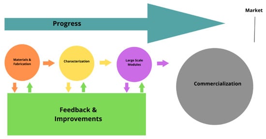
4. Commercialization
For future commercialization, although there are several challenges to be faced in fabricating perovskite PVs, some companies are in the early stages of developing perovskite PVs, e.g., Saule technologies [
190] and Quantum Solution [
191]. These developments are driven by perovskite’s wide bandgap, low-cost, and simple fabrication methods. For Saule technologies, they launched the first industrial production line of solar panels in May 2021 in Poland, based on groundbreaking perovskite technology. They are making sheets of solar panels using a novel inkjet printing procedure invented by the founder, Olga Malinkiewicz [
190].
However, the long-term performance of such a PV is an issue to pursue. As an example, the longest lifetime for the prototype was 6000 h under continuous one-sun illumination before degrading beyond 80% of its initial performance [
192]. Interfacial recombination can be a severely degrading performance issue, but some methods are used to inhibit this. In [
193], a 2D octyl-diammonium lead iodide interlayer was used to decrease recombination losses and obtain a PCE of 22.27% in tandem solar cells. A 2D/3D perovskite interface in [
194] suppressed interface losses with a PCE ≈ 21%. As an alternative, perovskite–silicon tandem PV has a better lifetime of 300 h of operation, and retained 95% of its initial efficiency without encapsulant, and performs at a PCE of 29.3% in comparison to the theoretical limit of 29% for the silicon PV [
195]. Therefore, the perovskite–silicon tandem PV is a prospective option for future commercialization; particularly, OxfordPV has pioneered producing their heterojunction silicon PVs to enhance their PV cells [
196].