Your browser does not fully support modern features. Please upgrade for a smoother experience.
Please note this is an old version of this entry, which may differ significantly from the current revision.
Subjects:
Polymer Science
Целью данной статьи является обобщение данных о структуре, механических и трибологических свойствах и характере изнашивания композитов на основе высокоэффективных полимеров (ВПП), предназначенных для использования в узлах трения.
- high-performance polymers
- antifriction composites
- transfer film
- wear rate
1. Введение
Целью настоящего обзора является обобщение данных о структуре, механических и трибологических свойствах и характере изнашивания композитов на основе высокоэффективных полимеров (ВПП), предназначенных для использования в узлах трения. Ряд таких материалов чрезмерно подробно описан в литературе, в частности чистый полиэфирэфиркетон (ПЭЭК) и композиты на его основе, в то время как аналогичный полимер полиарилэфиркетона (ПАЭК) редко подвергался исследованиям. В то же время политетрафторэтилен (ПТФЭ) не входит в этот список в качестве матричного материала, несмотря на то, что он чрезвычайно широко используется в качестве твердосмазочного наполнителя. Поводом для этого критического обзора послужили весьма неоднозначные опубликованные данные о влиянии одних и тех же типов наполнителей на трибологические свойства композитов, что многократно проиллюстрировано ниже.
В качестве ключевого критерия (верхний уровень классификации) принята контактная схема полимерных композитов и аналогов (точечная, линейная и плоская), поскольку она определяет макромасштабный уровень трибологического взаимодействия трущихся тел. Влияние других параметров учитывается при интерпретации сообщаемых значений коэффициента трения (CoF) и скорости изнашивания (WR), а также характерных механизмов, определяющих увеличение/уменьшение износостойкости.
Перспективность использования ТПС для создания материалов узлов трения определяется двумя их ключевыми свойствами: высокими температурами плавления и высокими прочностными характеристиками. Помимо приемлемого уровня индекса текучести расплава и способности обеспечивать межфазную адгезию к частицам/волокнам наполнителя (в том числе при достаточно высокой степени их содержания), эти материалы также привлекательны своей способностью к обработке и повышению жесткости/ грузоподъемность. Однако повышенные прочностные характеристики этого класса материалов одновременно определяют высокие уровни CoF, которые в большинстве случаев могут превышать 0,3 на стали в условиях сухого трения скольжения (DSF). По словам Брайана Дж. Бриско,1 ].
В последнее время особое внимание уделяется наполнению металлов и оксидов неметаллов (в частности, SiO 2 , SiC, ZnO, TiO 2 , Al 2 O 3 , Si 3 N 4 , CuO) наночастицами как способу повышения несущей способности. емкость и износостойкость полимерных композитов по сравнению с аналогами [ 2 ]. Кроме того, большое количество исследователей, изучающих композиты, загружали углеродные нанотрубки (УНТ) с целью укрепления полимеров, поскольку УНТ демонстрируют очень высокую прочность и жесткость.
Независимо от типов загружаемых наполнителей, неизменным условием повышения износостойкости является формирование тонкой и однородной трансферной пленки (ТП) или трансфер-пленочного слоя (ТПЛ) и ее надежное сцепление с контрагентом. Более тонкие TF, как правило, сильнее прилипают к противоположным поверхностям, чем более толстые. В связи с этим акцент при интерпретации результатов трибологических испытаний полимерных композитов смещается в сторону особенностей формирования и закрепления ТФ на аналогах. Кроме того, существуют два условия, определяющие способность полимерного композита образовывать такую пленку: 1) потеря полимерного материала в результате истирания вследствие взаимодействия с металлическими неровностями; и (2) его способность прилипать и сохраняться на поверхности контрагента в течение длительного времени.2 ]. К этому следует добавить и третье важное влияние на процесс изнашивания, а именно образование окисленного шлама в зонах трибоконтакта, в том числе из разрушенных ТП. Они могут как оказывать абразивное воздействие, так и выступать в роли третьего тела, облегчающего скольжение.
В качестве эффективного подхода к созданию антифрикционных полимерных композитов Ли Чанг [ 3 ] проанализировал формирование гибридных материалов, включающих одновременно как частицы твердой смазки, так и армирующие волокна. Синергетический принцип их действия (используется при интерпретации данных не менее 15% публикаций по теме настоящего обзора) характеризует схему на рис. 1 . В качестве ключевых трибологических аспектов отмечены следующие [ 3]: (1) Схемы «штифт на диске» (PoD) и «блок на кольце» (BoR) — это два широко используемых метода испытаний на износ скольжения. (2) Наличие армирующих волокон упрочняет полимерные композиты и защищает их от неровностей (неровностей) на сопрягаемых поверхностях, с одной стороны. С другой стороны, жесткие волокна могут повредить противоположные поверхности и препятствовать прикреплению к ним ТФ. Наконец, автор пришел к выводу, что «понимание роста TFL и их трибологического поведения на стадии стационарного износа все еще ограничено из-за отсутствия количественных методов» [ 3 ].]. Отметим, что исследователи композитов на основе ТП вкладывают в термин ТФ весьма разные понятия, несмотря на очевидность развития процесса изнашивания. По этой причине роль ТФ в формировании трибологических свойств может быть как отрицательной, так и положительной, даже обеспечивая трение в «безызносном» режиме.
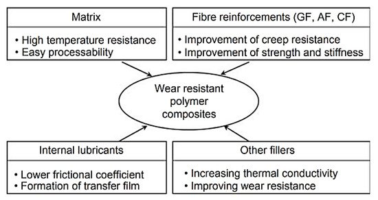
Рис. 1. Обзор структурных компонентов износостойких полимерных композитов. Рисунок воспроизведен с разрешения из ссылки [ 3 ].
In [4] Meghashree Padhan suggested some examples of hybrid ‘PEEK + PAEK’-based composites loaded with 30% short carbon fibers (SCFs) and 10% graphite (Gr) nanoparticles as primary solid lubricants (SLs), as well as 10% noncarbon secondary SLs such as WS2, MoS2, h-BN, etc. When interpreting the results, the effect of synergism between both types of SLs and the best efficiency of nanoparticles over microsized inclusions were considered.
The widespread use of nanofillers to improve wear resistance of polymer composites has prompted a significant number of reviews. For example, Qihua Wang emphasized [5] that nanoparticles alter friction and wear behavior in different ways. As a result, low CoF levels do not necessarily correspond to decreased WR values. At the same time, the factors affecting wear resistance are types of the combined polymer and nanoparticles, the filler content, and the friction contact size and shape in addition to operating conditions. Due to so many influencing factors, the effect of nanoparticles on the tribological properties of the antifriction polymer composites is still an open field for further research. This is especially the case when nanoparticles in combination with conventional fillers are considered. In doing so, a detailed analysis of the tribological behavior of various types of the composites with explicit consideration of the specific conditions of tribological tests is required.
A modification of M. Ashby’s concept on ranking structural materials over multidirectional functional properties [6] has been suggested for designing polymer composites for tribological purposes [7]. It considers WR, CoF and tensile strength levels of the polymer matrix, etc. (Figure 2). This approach is important due to its versatility since it enables the solution of the practically important issues of choosing polymer composites (including multicomponent ones) for given operating conditions. However, as noted above, the tribological properties depend on a number of parameters, so it is almost impossible to offer a completely universal approach within the framework of such data. As a result, a promising research area is the implementation of machine learning algorithms [3].
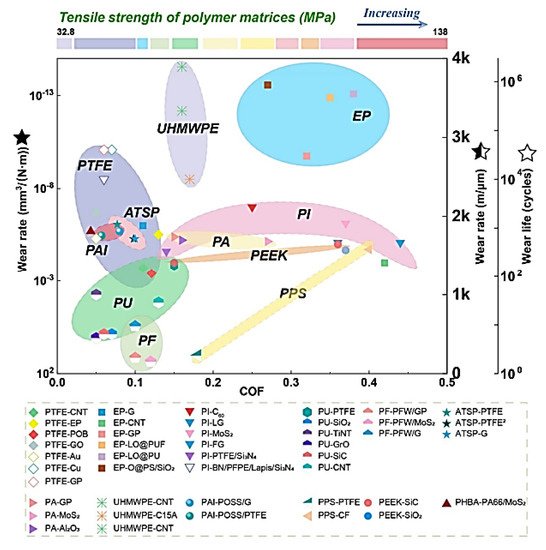
Figure 2. The tribological properties of different polymer matrices and fillers. Figure is reproduced with permission from reference [7].
The demand for HPPs in various industries has prompted a variety of reviews on their functional properties. In particular, Kurdi, A. et al. discussed the wear mechanisms under sliding friction for designing high-performance composites [8]. In this case, special attention was also paid to environmental factors, namely lubrication conditions, temperature, and even the possibility of developing vibration-induced phenomena. It was noted that loading with fillers may cause discontinuities in the polymer matrix, which promote the formation of debris. As a result, the critical filler contents should be limited to 5–15 vol.%. The role of nanoparticles in changing wear resistance narrows to both probable rolling effect and topographic smoothening of the friction surfaces. Similar to other authors in this field of science, Kurdi, A. and Chang, L. noted that the desired effect is achieved mainly by using a combination of reinforcing particles and fibers. However, an increase in both strength and toughness of HPPs does not always reduce the intensity of the wear mechanism development and the formation of debris.
Neat HPPs are not antifriction materials due to their high strength, which inhibits easy sliding on the counterpart (primarily steel) surfaces., This challenge is overcome in the design of composites by loading solid lubricant particles, followed by TF formation on the counterparts. However, the number of asperities on the sliding surfaces, determining CoF levels, also depends on the contact area. Three contact types are typically distinguished in tribology: point, line, and area (Figure 3) [4]. It is not too difficult to form a TF that is uniform in thickness and relatively firmly adhered on the surface of a steel ball at a point contact; however, this task becomes highly complicated for area contact types. The reason is lower specific pressures for this tribological loading scheme (as a rule). Temperature is another important aspect, since it is easier to realize heating followed by tribological oxidation and adhesion in a point contact than in both line and area ones. Due to this fact, the tribological test schemes have been accepted as the classification principle in this review.
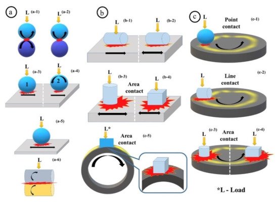
Figure 3. Various tribo-configurations and tribo-contacts: point contact (a-1 to a-5 and c-1), line contacts (a-6, b-1 and c-2) and area contacts (b-2, c-3 and c-4). Rotary motion (a-1, a-2, a-4, a-6, c-1, c-2, c-3, c-4 and c-5), Reciprocating linear motion (a-5, b-2, b-3, b-4), linear forward motion (a-3, a-4 and b-1). Figure is reproduced with permission from reference [4].
HPPs include polyethersulfone (PES), polyetherimide (PEI), polyphenylene sulfide (PPS), PEEK, fluoropolymers, etc. Their attractiveness lies in the possibility of replacing metal parts with nonmetallic ones in high-tech industries [9]. However, most papers on HPPs for tribological applications focus on a limited number of thermoplastics such as PPS, PEEK, and polyimide (PI). In this regard, numerous loaded fillers, their combinations, as well as schemes and conditions of tribological tests should be investigated on this topic.
Guowei Chen named CFs, CNTs, Gr, graphene (GN) and carbon black as the key fillers for PPS in his review [10]. Aspects of using biocarbon as an alternative for petroleum-based CFs loaded in PPS-based composites were also discussed. Some patterns of designing, processing, and studying functional properties of the PPS-based composites were also summarized in the review [11].
A significant number of papers on the use of PEEK-based composites are devoted to orthopedic applications. The authors are looking for ways to replace metal implants (components) with polymer ones, for which neat PEEK is often loaded with CFs [12]. In the design of PEEK-based composites for biomedical engineering applications, aspects of the polymer-filler interfacial interaction and their fabrication methods also play an important role. Oladapo et al. [13] noted perspectives of the PEEK-based composites from the point of view of the implementation of additive manufacturing (AM) procedures. Also, cellular calcium hydroxyapatite (CHAp) was analyzed as an advanced excipient. Another review [14] is devoted to the use of PEEK for designing biomedical composites and highlights its relevance in dental applications as well. In addition, PEEK is widely used for manufacturing knee, hip, spine and other implants in orthopedics. A review on dental applications of PEEK is given in [15]. Further analysis of the issue in its application for scaffolds was carried out by the authors of [16]. In a similar paper [17] Ma, H. et al. summarized some aspects of the performance requirements, the composite design process, and the surface modification when using PEEK as a material for the manufacture of orthopedic implants.
Because the tribological properties of the polymer composites are determined by their friction surfaces, some data on the PEEK surface modification have also been reviewed. In [18], Singh, S. analyzed plasma treatment of PEEK in terms of its influence on the biological, surface (adhesion and wettability), mechanical, and tribological properties. As noted above, some similar materials are gaining popularity in the development of HPP-based composites. In their review [19] Veazey, D., et al. proposed a roadmap for high-performance PAEK-based composites reinforced with long fibers (Figure 4). They emphasized that one of the key challenges in designing these composites is improving the fiber-matrix interfacial bond strength.
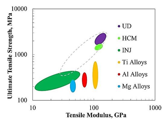
Figure 4. Typical tensile properties of common metallic alloys and CF-reinforced PAEK-based composites: UD, unidirectional fibers; HCM, hot compression molded fibers; INJ, injection molded fibers. Figure is reproduced with permission from reference [19].
The unique properties of PI have determined the prospects for some practical applications of PI-based composites. The most detailed review [20] covers the issues of their synthesis. It has been shown that the presence of functional groups and the formation of dendritic structures enable unique properties in PI-based composites. Their key advantage is the possibility of high-temperature applications. Nevertheless, some design challenges remain for the PI-based nanocomposites. For example, Ogbonna, V.E. emphasized [21] some issues of interfacial adhesion and surface degradation, which affect their mechanical properties and abrasive wear resistance in tribological applications. The following are considered fillers for such PI-based nanocomposites: CNTs, GN, graphene oxide (GO), boron nitride (BN), MoS2, silica (SiO2), titania (TiO2), alumina (Al2O3), CFs, aramid fibers (AFs), GF, zinc dioxide (ZnO2), zirconium dioxide (ZrO2), silicon nitride (Si2N4), and carbon nitride (C3N4). In [22] nanofillers of the mentioned types were reviewed from the standpoint of their influence on the structure and mechanical properties of the PI-based nanocomposites. Also, similar to the PEEK-based composites, the PI-based ones are used in medical applications. Some chemical, physical, and manufacturing aspects of designing the PI-based biocompatible composites are summarized by Catalin P. Constantin in [23].
2. Point Contacts
2.1. Neat HPP
In [24] Puhan, D. et al. tested neat PEEK on both steel and sapphire counterparts. It showed that the chemical compositions of the formed TFs differ from that of neat PEEK. The TFs mainly consisted of amorphous carbonaceous materials. Molecular chains of PEEK were broken in different positions of the ester and ketone groups. Additionally, opening of aromatic rings, substitution, and cross-linking, as well as both crystallinity and coplanarity losses were reported. As shown in Figure 5, a carboxylic acid formed, the interaction of which caused the formation of thin and strong TFs during friction with the surfaces of the steel or sapphire counterpart (PEEK; Ra = 1–1.2 µm; B-o-D; counterpart is a ball with a diameter of 6 mm; Ra = 0.02 µm; P = 10 N; V = 2 m/s; L = 3.6 km; Pmax = 160 MPa).
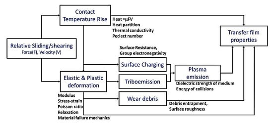
Figure 5. Factors effecting functional properties of polymeric TFs upon sliding PEEK on the steel surfaces. Figure is reproduced with permission from reference [24].
A number of papers are devoted to the effect of various surface treatment procedures on the tribological properties of PEEK. For example, Wang, M. showed the influence of engineered surface microstructuring on friction patterns in PEEK-steel contacts [25]. Pronounced fluctuations of CoF curves were observed in both nontextured and textured PEEK containing microholes with a diameter of 25 μm. This was accompanied by the formation of a noticeable amount of debris. In the case of friction of the GCr15 steel ball on the microtextured PEEK surface with holes 50 μm in diameter, the WR level was reduced sharply (PEEK; GCr15 ball; RF; Ra = 0.02 µm; B-o-F; DSF; LF = 0.9 and 3 N).
Cho, M. investigated the ability of PPS to form a TF while sliding on steel [26]. The steel counterpart surfaces were textured with four pore densities of 5, 15, 25, and 35% using a laser. Then, pores were filled with PPS powder followed by curing. This hybrid texturing protected the steel surfaces with formed TFs. An effective decrease in CoF levels was observed for the surface with the pore density of 5% at V = 0.15 m/s, in contrast to both V values of 0.05 and 0.10 m/s since high sliding speeds favored TF formation. In the case of the pore density of 15%, the CoF values were decreased for all sliding speeds, because TFs of moderate thicknesses covered all wear tracks (PPS; B-o-D; 100Cr6 steel ball; Ra = n/d; DSF; V = 0.05, 0.10, and 0.15 m/s; P = 9.8 N; L = 360 m).
Duan, C., et al. analyzed aspects of the influence of the PI molecular structure on the mechanical and tribological properties under conditions of incorporation of 4,4′-ODA into polyimide with 3,4′-ODA isomer [27]. It was shown that CoF levels were lowered with raising the 4,4′-oxydianiline (4,4′-ODA) content in the PI macromolecular chains. These changes were related to the macromolecular chain conformation caused by different monomer configurations. Thus, PI with paraposition diamine exhibited the best tribological properties (PI; B-o-F; RF; counterpart is the GCr15 steel ball with a diameter of 3 mm; Ra = n/d; P = 5 N; V = 0.1 m/s; Ampl = 2.5 mm; T = 20 °C; RH = 16–20%; L = 300 m).
In [28] Fareed, M. I. studied the tribological properties of PEEK by varying its structure through various heat treatment procedures such as annealing, normalizing, and both water and oil quenching from a temperature of 250 °C. The PEEK crystallinity reduced with an increase in its cooling rate. At the same time, the lowest crystallinity was found after water quenching. Conversely, the annealed samples showed the highest wear resistance because of the enhanced crystallinity. For each of these heat treatment procedures, WR levels increased with rising normal load (PEEK; B-o-D; Stainless steel ball; Ra = n/d; P = 30, 60, 90 N; V = 62.8 mm/s; L = 62.8 m; DSF).
Lubricating medium in a tribological contact changes conditions of TF formation. Tatsumi, G., et al. evaluated the role of organic friction modifiers (OFMs) in the lubrication improvement in PEEK-steel contacts [29]. Compared with OFM-A (oleylamine) and OFM-B (oleic acid), OFM-C (N-oleoyl sarcosine) showed a significant reduction in CoF levels in the ‘PEEK-smooth steel’ friction pair by 200% under sliding conditions and by 50% under the sliding-rolling ones. A similar CoF reduction was observed for OFM-C in both ‘PEEK-PEEK’ and ‘steel-steel’ friction pairs. A clear correlation between thicknesses of the PEEK TFs and the tribological properties of the ‘PEEK-steel’ friction pair was found. OFM-C exerted a great impact on these characteristics due to its ability to be strongly absorbed on both materials (Figure 6), inhibiting PEEK TF formation. This had both positive and negative effects on the tribological properties depending on the test conditions (PEEK; B-o-P; sliding/sliding-rolling; Ra = n/d; V = 1 m/s; P = 50 N (PEEK-steel and PEEK-PEEK); P = 5 N (steel-steel); T = 25 °C).
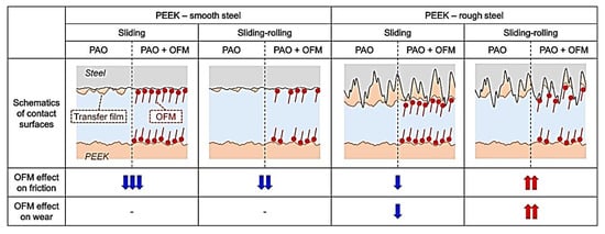
Figure 6. The OFM lubrication mechanism in the PEEK-steel contacts. Figure is reproduced with permission from reference [29].
An important aspect that determines the development of the tribological processes is temperature in the friction contacts. Laux, K.A., et al. used infrared thermography to observe the full field temperature map of PEEK upon its sliding on both stainless steel and sapphire counterparts [30]. It was shown that PEEK debris attaches easily to the steel counterpart but not to the sapphire one. The PEEK transfer to the steel surface may be accompanied by an increase in the sliding interface temperature (up to Tg). The PEEK TF was essentially oriented towards the steel counterpart surface. For this reason, TF formation was determined by the friction processes and the tribological contact temperature, which are not functionally dependent on the load-speed parameters (PEEK; B-o-D; counterparts are the sapphire ball with a diameter of 19 mm (Ra = 1.5 µm) and the 52,100 steel disc 46 mm in diameter (Ra = 10 nm); T = 25 °C; P = 1–40 N; V = 100 mm/s).
Yahiaoui, M., et al. studied the tribological behavior of the PEEK-steel contact in reciprocating or unidirectional motion by varying load, speed, and sliding distance [31]. CoF values were reduced due to lowering the load that decreased the contribution of molecular attraction forces, as well as because of the rising speed that cumulated the mechanical energy. The reason was the adiabatic effect in the contact, which changed the polymer rheology. As a result, two interfacial mechanisms were identified (Figure 7). The first one was the formation of Schallamarch ridges due to nanoscopic interaction between them. The longitudinal ploughing mechanism was responsible for the formation of microscopic scratches. During reciprocal sliding, the polymer relaxation strongly affected its tribological behavior. Unidirectional sliding caused greater plastic strains and stretched Schallamarch ridges in the sliding direction (PEEK; B-o-F; counterpart is the 100Cr6 steel ball with a diameter of 6 mm; reciprocating or unidirectional motion: (i) V = 100 mm/min, L = 250 mm, P = 1–30 N; (ii) P = 30 N, L = 250 mm, V = 10–500 mm/min; (iii) Ampl = 5 mm, L = 0.005–3.710 m; PEEK; Ra = 65 ± 9 nm).
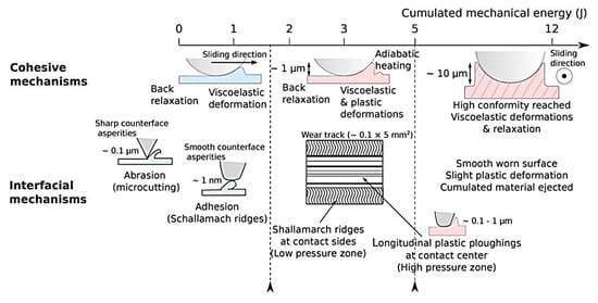
Figure 7. The cohesive and interfacial contact mechanisms as a function of the cumulated mechanical energy. Figure is reproduced with permission from reference [31].
For HPPs, one of the limiting factors for wear resistance is the (Tg) glass transition temperature. Jean-Fulcrand, et al. solved this issue by combining polybenzimidazole (PBI), having one of the highest Tg points, with PEEK in a ratio of 50:50 [32]. Chemical analysis of TFs formed on the steel counterpart surface and debris in the tribological contact showed the polymer degradation caused by shear heating. In the case of the ‘PEEK + PBI’ composite, TFs formed on the steel counterpart and possessed a composition similar to that of PEEK. When the contact temperature was close to the PEEK melting point, PEEK, as a composite component, formed a thin TF that acted as an interfacial lubricant. This reduced CoF levels, which in turn decreased the PBI degradation in the composite at high temperatures (PEEK-PBI; B-o-D; T = 100, 190, and 280 °C; DSF; V = 0.1–2.0 m/s; L = 3.6 km; P = 10 N; HAP = 116, 124 and 138 MPa; Ra(PBI) = 1.41 ± 0.43 μm; Ra(PEEK-PBI) = 1.27 ± 0.18 μm; Ra(PEEK) = 0.79 ± 0.15 μm; Ra(Steel) < 0.01 μm).
In [33] Zhang, G., et al. analyzed the effect of the amorphous structure of a PEEK film on its tribological properties. It was shown that there is no relative movement between a ball and the amorphous PEEK surface during the stick-slip sliding process due to the adhesion force in the interface zone. As a result, the material accumulated ahead of the counterpart. During the stick stage, shear stresses were less than the critical level required for adhesion between the sliding parts, but it increased with time. At high levels of the applied load, the tribological properties of amorphous PEEK could be closely related to its viscoelastic behavior, while the dominant factor was the ‘ironing’ effect at low load-speed levels. The change in the tribological properties of amorphous PEEK with an increase in sliding speed may be associated with the rising interfacial temperature. The critical load may be lower than that at which there is no pronounced viscous flow (PEEK; B-o-D; T = 20 °C; RH = 70%; counterpart is the 100Cr6 steel ball with a diameter of 6 mm; Ra = 0.02 μm; L = 2 km; P = 1–9 N; V = 0.2–1.4 m/s).
2.2. Reinforced HPP-Based Composites
Yamaguchi, T., et al. investigated wearing of PEEK-based composites loaded with particles of rice bran ceramics (RBC) under water lubrication (WL) conditions [34]. The ‘PEEK + RBC (10–40 wt.%)’ samples showed a decrease in both CoF and specific WR values over a wide range of the P·V conditions compared to those for neat PEEK. The authors suggested that the reason was the hydrodynamic lubrication effect. (PEEK; B-o-D; Ra = 0.14 µm; counterpart is the SUS 304 steel ball with a diameter of 8 mm; WL; V = 0.1–2.0 m/s; P = 0.98–9.80 N) Dong, F., et al. assessed the friction and wear behavior of neat PI and ‘PI + CF’ reinforced composites at various temperatures [35]. Loading with CFs significantly improved wear resistance over the entire temperature range, and CoF levels were highly dependent on the sliding contact temperature. It was found that the CF lubricity appeared only at high temperatures of 180–260 °C, which could be explained by their graphitization and subsequent TF formation on the worn surfaces with excellent lubricity (PI; B-o-D; Ra = 0.03 μm; counterpart is the GCr15 steel ball with a diameter of 3 mm; Ra = 0.02 μm; V = 0.3 m/s (573 r/min); P = 5 N; t = 30 min).
Lv, M., et al. reported the tribological behavior of PI-based composites reinforced with CFs and AFs under simulated space irradiation conditions and during the ‘start-stop’ friction process [36]. Loading with CFs and AFs contributed to lower CoF values and improved wear resistance of the composites, especially in the case of CFs. After UV irradiation, the composites maintained low both CoF and WR levels. This was attributed to continuous TF formation on the counterpart. It should be noted that tribological testing in the ‘start-stop’ mode resulted in rising WR values (PI; B-o-D; RT; vacuum of 10−4 Pa; counterpart is the GCrl5 steel ball with a diameter of 3.175 mm; Ra = n/d; V = 0.126 m/s; RR = 6 mm; P = 1 N).
Loading with thermally conducting fillers increases the thermal conductivity and the mechanical strength of polymer composites. Debashis Puhan et al. reviewed the effect of SCFs on the TF nature and the tribological performance of the ‘50% PEEK + 50% PBI’ composite upon friction on the steel counterpart at temperatures up to 300 °C [37]. The TF contained materials mostly related to SCFs. As a result, the CoF level reduced compared to those for neat PEEK and PBP, especially near the (TgPEEK) glass transition temperature of PEEK, when the TFs were relatively thick. At 300 °C, the ‘PBP + SCF’ TF became thin, possibly due to abrasion by SCFs dislodged from the matrix. Below the Tg PEEK level, the ‘50% PEEK + 50% PBI’ composite was characterized by greater WR values than that for neat PEEK, while thick TFs formed above this temperature and wear resistance of the composite was enhanced (PEEK-PBI; B-o-D; counterpart is the AISI 52100 steel ball with a diameter of 6 mm; Ra = n/d; DSF; P = 10 N; V = 1 and 2 m/s; T = 25, 100, 145, 200 and 300 °C; L = 3.6 km).
In [38] Jacobs, O., et al. analyzed the effect of the counterpart material (the 100Cr6 and X5CrNi18-10 steels, alumina, and a bronze) on WR levels of PEEK-based composites loaded with CFs, GF, PTFE, and Gr at low P·V values under DSF and in an aqueous medium. At the DSF conditions, the lowest WR level was typical for stainless steel, while the best results were observed for alumina in the aqueous environment. The ‘GF + PTFE’ composite showed the greatest wear resistance. CFs are preferred for friction in water as they react very susceptibly with this environment. As a rule, friction in the aquatic medium contributes to increased WR values. It has been shown that the filler material can change the WR levels by several orders of magnitude at the minimum achieved level of ~10−8 mm3/Nm. Correctly choosing the counterpart materials could more effectively improve wear resistance of the composites than thorough designing their compositions (B-o-P; unidirectional sliding; Rz(100Cr6) = 0.15 µm; Rz(X5CrNi18-10) = 0.31 µm; Rz(Al2O3) = 0.46 µm; Rz(bronze) = 0.33 µm; P = 30.0 N; P = 21.2 N; RF = 1 Hz; V = 28.2 mm/s; L = 6 km; CP = 3–27 MPa; P·V < 0.76 MPa m/s).
Greco, A.C., et al. tested both neat PEEK and composites reinforced with short randomly oriented fibers (SROF) as well as long woven fibers (LWF) at high sliding speeds [39]. The presence (and morphology) of such fibers significantly affected the wear mechanisms under these test conditions. CoF levels decreased with increasing the load for all tested materials. The ‘PEEK + LWF’ composite had the lowest CoF level (50% fewer than that after loading with SROF). The same was relevant to the ‘PEEK + LWF’ one, whose WR value was an order of magnitude lower than that of the ‘PEEK + SROF’ sample. In the case of high loads, the WR level of the ‘PEE + LWF’ composite increased due to fracture of fibers, the abrasive wear of the counterpart surface, and TF removal (PEEK; B-o-D; counterpart is the 440c steel ball with a diameter of 4.76 mm; ball-on-disc unidirectional sliding; Ra = n/d; P = 0.73, 2.50, 5.00 and 10.00 N; MHS = 50–600 MPa).
When designing PI-based composites for high-temperature applications, 3-APTES and its modification with lanthanum (La) salt can be used for improving the interface properties. As an example, Yu, L., et al. investigated ‘PI + poly-p-phenylenebenzobisoxazole (PBO)’ samples [40]. They reported that the PBO fiber surface modification with La salt was the most efficient. CoF levels decreased for all studied composites with rising load-speed parameters at both T = 130 and 260 °C, while WR values increased in this case. In contrast to T = 130 °C, wear resistance of the unmodified composite was highly dependent on both load and speed parameters at T = 260 °C. For comparison, the modified one was less affected. Under the same tribological test parameters, the ‘PI + PBO-La’ composite showed the lowest specific WR and CoF levels (PI; B-o-D; counterpart is a metal ball of 89 HRA; Ra = 0.1 μm; T = 130 and 260 °C; t = 60 min; P = 3–12 N; V = 0.25–1.00 m/s)
Li, E.Z., et al. reported the effect of applied load and sliding duration on both CoF and WR levels of the ‘PEEK + 30 wt.% GF’ composite [41]. It was shown that these characteristics gradually increased and remained stable with both rising tribological test parameters. The composite possessed a markedly higher wear resistance compared to that for neat PEEK. GF were extruded from the composite rather than pulverized into it. The thermal decomposition temperature increased by 75 °C for the composite compared to that for neat PEEK. (PEEK; B-o-D; Ra = n/d; RT; P = 100–400 N; t = 30 and 120 min).
2.3. Solid-Lubricant Fillers
After loading with SLs, TF formation is determined by a mechanism providing an increase in the polymer wear resistance (primarily due to a decrease in CoF values). Duan, C., et al. developed an effective approach for improving the high-temperature wear resistance of thermoset PI (TPI) by loading it with g-C3N4 (0.5–5.0 wt.%) [42]. In a range of room temperature up to 350 °C, wear resistance of these composites improved greatly and reached 7.29 × 10⁻⁷ mm3/Nm (T = 350 °C at the g-C3N4 content of 5 wt.%). The observed effect was achieved due to TF formation, containing g-C3N4 with both high elastic modulus and hardness levels. This enabled the composites to effectively redistribute loads on TPI and prevent resin from abrading at the contact surfaces (PI; B-o-P; Ra(TPI) = 0.093 µm; counterpart is the GCr15 steel ring with a diameter of 3 mm; P = 5 N; V = 0.1 m/s; L = 1 km; t = 166 min; RT, 100, 200, 250, 300 and 350 °C).
The authors of this review initially did not plan to analyze PTFE-based composites, but one such paper is of particular interest. In [43] Zhao, Y., et al. studied the effect of loading PTFE with silicon dioxide (SiO2-PI) in amounts of 0–15 wt.% and porous PI (0–15 wt.%) on the tribological properties of the composites. Compared to loading with neat PI, the addition of SiO2-PI and porous PI resulted in loose structures of the PTFE matrices and uneven worn composite surfaces. This promoted the formation of smooth and uniform TFs. In contrast to loading PTFE with SiO2-PI, the addition of SiO2 nanoparticles into the ‘PTFE + PI’ compounds induced the formation of rough and uniform TFs, which were detrimental to the tribological performance of the ‘PTFE + PI + SiO2′ composites (PI, B-o-F, Ra = n/d; P = 200 N; stroke length = 15 mm; frequency = 2 Hz; t = 120 min; counterpart is the GCr15 steel ball with a diameter of 9.5 mm).
Concerning hybrid HPP-based composites, their loading with SLs and reinforcing fibers is a typical solution for improving functional properties. Song, J. investigated insulated PI-based ones filled with SGF, PTFE, SiO2 and PPL [44]. When replacing CFs and Gr with GF and PTFE, both CoF and WR parameters were reduced. The achieved high tribological characteristics were interpreted as a synergistic effect of the simultaneous loading of the PI matrix with GF, PTFE, SiO2, and PPL (PI; B-o-D; counterpart is the Si3N4 ball with a diameter of 4 mm; Ra = n/d; V = 0.063 m/s; P = 3 N; t = 6 h.
In addition to the production of bulk polymer composites, the formation of coatings is a perspective. Demian, C., et al. developed thermoset PI-based composite coatings on aluminum substrates [45]. PTFE and SiC (up to 5 wt.%) fillers were added into neat PI. It was shown that loading with PTFE significantly reduced CoF levels of the ‘PI + PTFE + SiC’ composite coatings, as PTFE particles contributed greatly to the reduction in the total surface energy. The ‘PI + 20% PTFE + 5% SiC’ composite coating was characterized by a low CoF value with a slightly decreased WR level as well as satisfactory hardness compared to those for other ‘PI + PTFE + SiC’ samples. (PI; B-o-D; counterpart is the 100C6 steel ball with a diameter of 6 mm; Ra = 0.02 μm; V = 0.4–0.8 m/s; P = 5 N) Zhang, G., et al. studied two PEEK-based coatings deposited on aluminum substrates by flame spraying and printing [46]. After annealing at 260 °C for 30 min, an initially amorphous coating obtained a semicrystalline structure, possessing both lower CoF and WR levels. The addition of SiC microparticles and Gr into the PEEK-based coatings significantly improved their wear resistance (PEEK; B-o-D; counterpart is the 100Cr6 steel ball with the diameter of 6 mm; Ra = 0.02 μm; P = 5 N; V = 0.2 m/s; L = 2 km).
Lal, B., et al. analyzed a series of PEEK-based composites loaded with PTFE particles (0–20 wt.%) [47]. The addition of the latter enabled enhanced ultimate load values, eliminated the stick-slip tendency, and greatly decreased both CoF and specific WR parameters. The lowest CoF value was recorded at 15% PTFE. At T = 100 °C, the CoF and WR levels increased slightly for all studied composites. On the other hand, the composites showed lower wear resistance than neat PEEK in the abrasion tribilogical mode (PEEK, B-o-P; counterpart is the 100Cr6 steel ball with a diameter of 10 mm; Ra = n/d; frequency = 50 Hz; RT; L = 360 m; T = 100 °C; P = 50 N).
2.4. Nanofillers
As noted above, the role of nanoparticles in HPP-based composites for tribological applications narrows to (1) reinforcing the polymer matrix; (2) (solid) lubricating (with correct compositions); (3) stimulating TF fixation on counterparts. The most ‘popular’ types of nanofillers were also listed. Results of a number of papers devoted to the point composite-counterpart contacts are summarized below.
Zhao, Y., et al. fabricated ‘PI + nano-SiO2’ (0–25 wt.%) composites via in situ polymerization [48]. First, CoF levels of the composites decreased by 6.8% with an increase in the nano-SiO2 content from 0 to 5 wt.%. Then, they enhanced CoF levels by 11% with raising the content up to 25 wt.%. At the nano-SiO2 contents of 5–10 wt.%, WR values of the composites were greater than that for neat PI. Formed TFs delaminated easily, and nano-SiO2 particles tended to be accumulated on the friction surfaces. These factors reduced wear resistance of the composites (PI; B-o-D; Ra = n/d; RT; t = 1.5 h; V = 0.04 and 0.08 m/s; P = 5 and 10 N; counterpart is the GCr15 ball with a diameter of 3 mm). Zhou S., et al. investigated PI-based composite coatings composed of CNTs and fluorinated graphene (FG), in which both hybrid and blend phases were mixed via solution doping [49]. A significant increase in the mechanical properties was accompanied by a decrease in WR levels by 61%. For the ‘PI + CNT + FG’ composite coating, the CNT strengthening effect and the FG lubrication characteristics were fully manifested in the blend phase (PI; B-o-D; Ra = n/d; SF = 2 Hz; DSF; t = 30 min; P = 5 N; counterpart is the GCr15 steel ball with the diameter of 3 mm).
In [50] Chen, B., et al. prepared multiscale ‘CF + CNT’ PI-based composites using a chemical method. The composites possessed many functional groups and increased roughness. CoF and WR values of the ‘PI + CF + CNT’ composites were 0.213 and 1.79 × 10⁻⁶ mm3/Nm, i.e., decreased by 22% and 72%, respectively, compared to those for neat PI. Also, both CoF and WR levels decreased by raising the load-speed product. Thus, CNTs stretched into the PI matrix on the hybrid ‘CF + CNT’ surface, which had a reinforcing effect even at high load-speed parameters (B-o-F; RS; counterpart is the GCr15 ball; Ra = n/d; DSF; t = 30 min; P = 1.5–4.5 N; LRV; V = 0.05, 0.083 and 0.116 m/s).
Nanofillers are made in complex shapes to improve their adhesion. Yuan, H., et al. loaded PI with MoS2 nanoflowers (0.5–1.5 wt.%) through grafting them onto the surfaces of hollow CNFs (HCNFs) [51]. The ‘PI + MoS2 + HCNF’ composite coatings showed high wear resistance under WL conditions (with a filler content of 0.5 wt.%, the WR reduction was 72.5%) and in liquid paraffin oil (with a filler content of 1.5 wt.%, the WR value decreased by 56.0%) (PI; B-o-P; the counterpart is the GCr15 steel ball with a diameter of 6 mm; Ra=; RT; RH = 25–30%; HCP = 112 MPa; P = 20 N; V = 1.2 cm/s (20 Hz); t = 30 min). Graphitic carbon nitride (g-C3N4) is being extensively investigated by many researchers as a nanofiller for improving the tribological properties of PI-based composites. For example, Zhu, L., et al. showed [52] that its contents from 0.5 up to 2.0 wt.% had a decisive influence on the tribological properties of the ‘PI + g-C3N4’ composites. CoF kinetics gradually decreased with raising the g-C3N4 filler concentration but increased above 10 wt.%. At its low contents, the wear type was adhesive, while it changed to abrasive with excessive g-C3N4 levels (PI; B-o-D; Ra = n/d; DSF; reciprocating testing; P = 2, 4 and 50 N; counterpart is the GCr15 ball with the diameter of 6 mm; t = 10 min; V = 0.42 m/s; RT; RH = 40%).
Chen, B., et al. designed a novel hybrid PI-based composite with micro-CFs and hexagonal MoS2 nanosheets (0.5–20.0 wt.%) via a one-step hydrothermal method [53]. The hybrid simultaneously exerted both lubricating and strengthening effects on the PI matrix. This contributed to transferring stresses from the matrix to CFs during friction and wear. The ‘PI + CF + MoS2’ composite showed advanced tribological properties. CoF and WR values were equal to only 0.24 and 2.01 × 10⁻⁶ mm3/Nm, respectively, which were lower than those for neat PI, as well as for both ‘PI + CF’ and ‘PI + MoS2’ composites. Additionally, self-lubricating MoS2 nanosheets gradually exposed on the worn surfaces, making it easier to slide (PI, B-o-F; Ra = n/d; P = 3 N; V = 0.083 m/s; t = 30 min).
Min, C., et al. fabricated PI-based nanocomposites using different contents of amine-functionalized graphene nanosheets (AGNS) via in situ polymerization [54]. In contrast to neat PI and ‘PI + GNS’ composites, the ‘PI + 0.5 wt.% AGNS’ sample was characterized by both reduced CoF and specific WR (by 41.9% and 72.6%, respectively. Under DSF conditions, this effect was provided by strong interfacial adhesion and good compatibility between AGNS and PI (Figure 8). In addition, the ‘PI + AGNS’ nanocomposite showed excellent wear resistance in seawater at CoF = 0.16 and WR = 1.68·10−4 mm3/Nm (PI, B-o-D; Ra = n/d; DSF, SWL; V = 300 r/min; t = 30 min; P = 5 N; the counterpart is the GCr15 steel ball with a diameter of 4 mm).
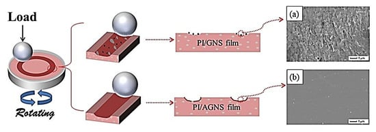
Figure 8. A model of the friction mechanism for the ‘PI + GNS’ and ‘PI + AGNS’ films. The inset is the SEM images of worn surface of (a) PI/GNS-1wt.% nanocomposite and (b) PI/AGNS-1wt.% nanocomposite. Figure is reproduced with permission from reference [54].
Zhou, S., et al. investigated ‘PI + FG’ nanocomposite films (FG is fluorinated graphene in amounts of 0.5–2.0 wt.%) under different friction conditions [55]. CoF levels of the nanocomposites decreased slightly compared to that for neat PI. During the DSF tribological test, a WR value reduced by 51.2% for the composite with the optimum filler content of 0.5%. However, the WR levels decreased significantly for all samples due to the softening effect of water on the ‘PI + FG’ mixture, indicating that they were unsuitable for operation in aqueous environments. The presence of products of tribochemical reactions on the wear track surfaces provided an antiwear effect and reduced the CoF values (Figure 9). The FG layer covered the steel counterpart surface and formed a dense TF. Also, it reduced the CoF values and improved wear resistance (PI; B-o-D; the counterpart is the GCr15 steel ball with a diameter of 3 mm; Ra = n/d; frequency = 5 Hz; P = 10 N; t = 30 min; DSF, SLF). Min, C., et al. designed the ‘PI + 0.5 wt.% FGO’ nanocomposite [56]. Due to covalent bonds, the great FGO to PI interfacial adhesion increased their mechanical strength and wear resistance. At 0.5 wt.% FGO nanosheets, both CoF and WR parameters were reduced by 33.1% and 80.8%, respectively, compared to neat PI under the DSF conditions. In SWL, a CoF level was equal to 0.22, while the WR value of 0.45·10−4 mm3/Nm was registered (PI, B-o-D; Ra = n/d; DSF and SWL; P = 5 N; V = 300 r/min; t = 30 min).
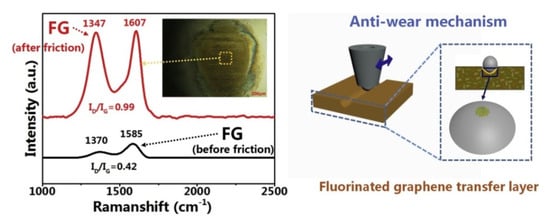
Figure 9. A schematic presentation of the tribological mechanism for the ‘PI + FG’ nanocomposites. Figure is reproduced with permission from reference [55].
In [57] Zhao, Z., et al. used CeO2 nanoparticles (about 80–110 nm, 0–9 wt.%, prepared via in situ synthesis) for strengthening ‘PAI + PTFE’ coatings. At a concentration of CeO2 nanoparticles of 5 wt.%, the worn coating surface was the least damaged. During friction, substance transfer was observed, accompanied by tribochemical reactions. Due to TF formation, it was possible to exclude direct contact between the components of the mating materials (Figure 10), which improved their wear resistance. It was concluded that the ‘PAI + PTFE’ coatings are more suitable for high sliding speeds at low loads (PAI; B-o-F; Ra = n/d; LRF; Dist = 5 mm; P = 5 N; V = 10 cm/s; L = 400 m; RT; AH = 35–55%).
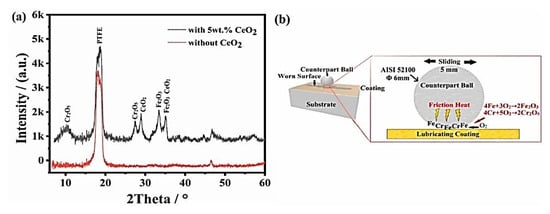
Figure 10. (a) Results of XRD analysis of the worn ‘PAI + PTFE’ coating surface and (b) a scheme of the tribochemical reactions. Figure is reproduced with permission from reference [57].
Puértolas, J. A., et al. used the lubricant capability of graphene nanoplatelets (GNPs) to improve PEEK tribological properties [58]. Nanocomposites were fabricated by solvent-free melt-blending and injection molding at the filler contents of 1–10 wt.%. The CoF reduction was about 83% for the ‘PEEK + 10% GNP’ composite. This effect was associated with an increase in its hardness. At high GNP contents, the wear mechanism was fatigue, while the abrasive one dominated at the lowest concentrations. At the filling degrees of 3–5 wt.%, it was possible to reduce both CoF and WR at constant elastic modulus and strength levels (PEEK; B-o-D; Ra(PEEK) = 1 μm; counterpart is the alumina ball with a diameter of 6 mm; Ra = 0.050 ± 0.002 μm; WL; T = 37 °C; P = 5 N; HCP = 37 MPa; V = 0.05 m/s; L = 0.18, 2.16 and 4.52 km). Due to the widespread use of PEEK in the field of artificial joint materials, Ting Wu et al. in situ integrated nano-ZnO particles (2.5–7.5 wt.%) in the PEEK powder surfaces by a one-step hydrothermal method [59]. As a result, their compressive strength reached 319 MPa, while the lowest WR level was 0.48 × 10⁻⁶ mm3/Nm for the ‘PEEK + 5% nano-ZnO’ composite, which was 68% lower than that for neat PEEK, according to Figure 11 (PEEK; P-o-D; Ra = n/d; RLS; counterpart is the CoCrMo pin with a diameter of 10 mm; Dist = 10 mm; P = 30 N; V = 5 mm/s; t = 120 min; RT; 25% CSL).
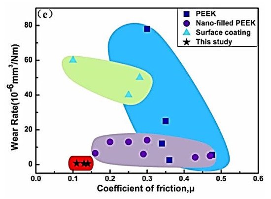
Figure 11. The WR vs. CoF diagram by Ashby (Zhang, 2010; Panin et al., 2021; Yan et al., 2020; Wang et al., 2017; Tharajak et al., 2015, 2017). Figure is reproduced with permission from reference [59].
As a summary of this section, it is appropriate to cite the paper [60] by Guo, L., et al., that reviews papers on tribological test results of PEEK-based composites using the pin-on-disk scheme published in the last 20 years and provides new experimental data. In their research, PEEK was reinforced with CFs and loaded with Bi2O3 and SiO2наночастицами, а также с обычными СЛ (Гр и ПТФЭ). Частицы SL улучшают износостойкость при низких скоростях скольжения, особенно при незначительных нагрузках. Реакции хелатирования между ПТФЭ и стальным аналогом, а также перенос графитовых материалов, образующих обломки Gr и CF, были основными механизмами роста TF. При скольжении при Р = 1 МПа и скоростях от 0,05 до 0,20 м/с дополнительное нагружение наночастицами Bi 2 O 3 значительно снижало уровни WR композита на основе ПЭЭК, армированного УВ. При более высоких давлениях или более низких скоростях эффект наночастиц Bi 2 O 3 был незначительным. При малых нагрузках и относительно высоких скоростях высвобождение Bi 2 O 3наночастицы на поверхности трения улучшают несущую способность ТФ. Положительная роль наночастиц SiO 2 проявилась при Р = 30 МПа и V = 0,1 м/с. В случае скольжения при Р = 30 МПа и V = 0,01 м/с большая нагрузка и относительно высокая скорость способствовали формированию прочного ТФ, армированного SiO 2 . Противоизносная роль СЛ была наиболее выражена как при малых нагрузках, так и при малых скоростях (PEEK; PoD; аналоги полимерные штифты и диск из стали GCr15; R a = 0,25 мкм; DSF; RT; радиус = 16,5 мм; V = 0,01– 0,20 м/с, P = 1–30 МПа, t = 5 ч).
This entry is adapted from the peer-reviewed paper 10.3390/polym14050975
This entry is offline, you can click here to edit this entry!
