Masonry-Infilled Reinforced Concrete Frames are a very widespread structural typology all over the world for civil, strategic or productive uses. The damages due to these masonry panels can be life threatening to humans and can severely impact economic losses, as shown during past earthquakes. In fact, during a seismic event, most victims are caused by the collapse of buildings or due to nonstructural elements. The damage caused by an earthquake on nonstructural elements, i.e., those not belonging to the actual structural body of the building, is important for the purposes of a more general description of the effects and, of course, for economic estimates. In fact, after an earthquake, albeit of a low entity, it is very frequent to find even widespread damages of nonstructural elements causing major inconveniences even if the primary structure has reported minor damages. In recent years, many territories have been hit worldwide by strong seismic sequences, which caused widespread damages to the nonstructural elements and in particular to the masonry internal partitions and the masonry infill panels of the buildings in reinforced concrete, with damage to the floor and out-of-plane expulsions/collapses of single layers. Unfortunately, these critical issues have arisen not only in historic, but also in recent buildings with reinforced concrete, in many cases exhibiting inadequate seismic behavior, only partly attributable to the intrinsic vulnerability of the masonry panels against seismic actions. Such problems are due to the following aspects: lack of attention to construction details in the realization of the construction, use of poor-quality materials, and above all lack of design tools for the infill masonry walls. In 2018, regarding the design of nonstructural elements, the formulation of floor spectra has been recently introduced in Italy. This entry article wants to focus on all these aspects, describing the state of the art, the literature studies and the design problems to be solved.
- infilled RC frames
- nonstructural elements
- earthquake damages
- macro-models
- seismic behavior
1. Introduction
In the complex of a building, are distinguished load-bearing and non-load-bearing elements. The former constitute the structure of the building and they are entrusted with the task of transmitting the vertical and horizontal actions acting on the building. The latter, on the other hand, are entrusted with other tasks:
- delimitation of the building envelope (infill);
- separation between internal environments (partitions);
- environmental comfort (acoustic insulation, thermal insulation, visual comfort, fire resistance).
In particular, the internal partitions fall within the family of vertical closures, i.e., they are those factory elements, of any shape, which constitute the vertical envelope of the built space and also represent the elements of separation between the external and internal microclimate.
Furthermore, in each structure, vertical elements and horizontal elements are also distinguished, and with them the load path is defined, which normally starts from the horizontal ones, continues in the vertical ones and leads them up to the foundation. In the case of structures in masonry, the vertical elements are made up of load-bearing walls, while in the reinforced concrete structures the vertical elements are the pillars. In the first case, therefore, load-bearing and nonbearing walls coexist, while in the second case, the structure is divided into compartments and delimited from the external environment by partitions that theoretically have no static function.
In reality, however, these non-load-bearing walls (infill walls) made within the meshes of the frames—although not considered, in the calculation phase of the structure, to be resistant to any force—influence the behavior of the structure subject to seismic events in terms of increased stiffness and resistance to lateral loads, as well as a significant increase in dissipative capacity.
In fact, the bare frames are designed with reference to bending regimes with the formation of plastic hinges at the nodes under the effect of lateral loads, while in the buffered frames, a mechanism is established in the panel that creates a bracing and traction effect in the pillars. Therefore, a different distribution of acting forces arises which gives rise to stresses not foreseen in the calculation phase, in the absence of partitions and infill panels.
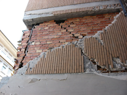
This increase in stiffness, in some cases, allows the structure to adequately resist intense and prolonged seismic actions only thanks to the presence of infill walls, which allow a greater dissipation of the quantity of energy entering the system. Their contribution is demonstrated by the classic X-shaped cracks which indicate a shear failure under cyclic loads (Figure 1).
(a)
(b)
Figure 1. (a). Classic X-shaped infill lesion with intact supporting structure; (b). Typical expulsion of infill masonry wall. [1].
However, the presence of infills does not always create a beneficial effect on the structure subject to an earthquake. In fact, due to the high stiffness, the infill panels can originate irregular plan configurations, jeopardizing a correct upstream structural configuration. These situations can also occur starting from a situation of regularity following a collapse of some wall panels which causes an imbalance in the stresses acting on the structural elements. This occurs because of the high fragility of the materials and because the breakage is a result of the loss of balance outside the plane due to the ineffectiveness of the connection with the structure and due to instability phenomena linked to the reduced thickness of the wall panels compared to the others.
In fact, the seismic behavior of buildings is significantly influenced by presence of masonry infill panels, as is now recognized by numerous studies, as well as reconnaissance for the relief of post-earthquake damage. Although in some cases the presence of rear-end collisions has positive effects on structural behavior, the walls are often susceptible to high levels of damage, even to the expulsion of the panel, particularly dangerous due to falling debris. Despite the critical importance of the infill walls to safeguard life, the presence of the panels is often neglected in the design and numerical modeling phases, as the same they are formally nonstructural elements.
1.1. Reinforced Concrete Frames with Masonry
The structures can be assimilated to real organisms consisting of a series of structural elements that collaborate with each other in a synergistic way and allow the loads to discharge to the ground. The structure, however, is not only made up of these structural elements, whose main function is precisely that of allowing the structure to exist and not to collapse under the effect of loads, but it is also made up of many elements which, although not performing a structural function, are however very important, if not fundamental, as they make the structure usable.
These elements, defined precisely as nonstructural elements, can be of an architectural nature (balconies, false ceilings, plasters, partitions, etc.), plant engineering (electrical, ventilation, heating, gas, etc.), may have a function associated with the safety of utilities (escape routes) or can simply be linked to the furniture (shelving, bookcases). However, being classified as nonstructural elements does not make them any less important. In fact, with reference to the seismic events that have struck Italy in recent years, the damage, or in some cases the actual collapse, of these nonstructural elements has caused even irreparable damage to the structural organism to which they belonged (making it unusable and therefore subject to demolition), as well as damage to people. To support the thesis according to which these elements, although not having a purely structural function, play an absolutely not marginal role in terms of safety, reference is made to the Technical Construction Standards 2018 (NTC18 [2]) which in § 7.2.3 define the nonstructural elements as follows: “By nonstructural construction elements we mean those with stiffness, strength and mass such as to significantly influence the structural response and those which, while not affecting the structural response, they are nonetheless significant for the safety and/or safety of people.”
As specified by the legislation, the nonstructural elements do not have a load-bearing function, i.e., their absence does not affect the structural stability; however, they significantly influence the behavior of the structural organism to which they are associated, but above all they can cause damage to people if they are not well designed. Non-structural elements require careful design which is often not carried out in design practice, causing, as already described, serious accidents during earthquakes.
One of the most important nonstructural elements, which has attracted the attention of many researchers in the sector in recent years, is represented by infill masonry walls. The reason for this is straightforward: the most common construction type in many countries of the world, but especially in Europe (including Italy), is represented by reinforced concrete frame structures. The supporting elements of these structures, by their very nature, do not allow one subdivision between internal and external space; therefore, it is necessary to introduce elements of a nonstructural nature that are able to perform this function. In this regard, the best element for economy, ease of installation, versatility and thermal and acoustic performance is represented by the masonry infill. The masonry infill is nothing more than the set of different brick elements (bricks and/or blocks, perforated or not) connected to each other usually with mortar, but it is not uncommon to see other types of binders used (curtain walls represent an example with glue joints). They are superimposed on each other to fill the various perimeter spans of the frame structure to create a separation between the internal and external environments. Obviously, some of these infill walls will have openings which will then be filled with fixtures of various kinds. Often, to improve performance in terms of thermal and acoustic insulation, the masonry infills are made by coupling two layers of brick separated from each other by a filled cavity with insulating material or simply left empty.
In the field of residential constructions, infill panels are usually made of nonreinforced brick. On the contrary, in the field of structures for industrial use, given the larger dimensions and different needs, the type of masonry infill increasingly used is reinforced, characterized simply by the presence of reinforcement pylons placed in correspondence with the sick beds. However, it should be noted that below, with the term plugging, we will always and only refer to plugging in nonreinforced masonry.
On the basis of this description, it is easy to understand how, by its nature, the infill wall is not conceived as an element capable of fulfilling a load-bearing function, which is why it is often neglected from a structural point of view: the less attentive designers, in fact, deal with the design of the load-bearing elements (beams, pillars, curbs, floors, etc.), completely forgetting that these structural elements, during the useful life of the work, will have to collaborate with other nonstructural elements, such as curtain walls, and that the presence of these will necessarily influence it.
This way of designing is justified: the infill walls are made only after the frame structure has been completed, thus releasing them from any load-bearing function against vertical loads. In addition, the utilities and/or the intended use of the structure may change, and with them the arrangement of the openings may also change, which makes the infills susceptible to mutations and makes modifications over time difficult to predict in the design phase.
These might seem to be sufficiently valid reasons to justify the negligence of rear-end collisions in the design phase, but they are not as we will see better below.
First of all, to avoid those tensional states associated with the action of external loads that may arise inside the infills (thus giving these elements a load-bearing structural function when these, as they were conceived, do not have), it is good to realize the infills starting from the top floor of the building and then gradually descend towards the lower floors. This is a good rule of thumb that avoids loading the infill panels by creating first those of the higher floors and then cascading those of the lower floors; the vertical load associated with the elastic deformation suffered by the elements of the frame is not severe on the rear-end collisions themselves. Therefore, operating in this way, it will not be possible to consider the contribution of rear-end collisions to withstand vertical loads representing a valid and justified approximation. Another thing is the negligence of rear-end collisions with respect to horizontal actions, in particular from the stresses deriving from seismic events.
2. Numerical Modeling and Structural Response of Masonry Infills
Since the early 1960s, with the aim of adequately describing the behavior of framed structures with masonry infill, two main modeling approaches have been distinguished: macromodels and micromodels (Crisafulli, Carr and Park [3]). However, there are also other approaches (Lourenço [4]), which possess homologous and intermediate characteristics between the two mentioned above. The foremost variances between them are the accuracy and the calculation burden. The micro-modeling takes into attention all the components, while the macro-modeling considers the whole wall panel as a homogeneous unit. The latter is generally used in the case of a global response, and its influence on the behavior of reinforced concrete infilled frames is considered.
2.1. Types of Numerical Models
The micromodels (P. G. Asteris [5]) provide for the nonlinear finite element modeling of the reinforced concrete frame, of the infill panels and therefore of the interference and the connection between the frame and therefore the wall. Although this type of approach is more accurate, there are several drawbacks in their use, mainly related to their complexity and the associated computational burden required for numerical analyses. These characteristics make them more suitable for research uses, rather than for the design and verification of the various walls generally present in real structures. This is why, in fact, macro-models are basic logic models, which simulate the general force-deformation behavior of the wall with respect to experimental results (Lam [6]).
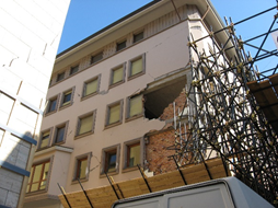
The macro-models that describe the behavior of the masonry panels require less calculation costs related to numerical analyses and are therefore more suitable for representing the overall behavior of the structures. Fardis and Panagiotakos [7] and P. Asteris [8] propose a series of analytical macro-models for the analysis of infilled frame structures, mainly dividing them into single strut models of two orders (Figure 2a) and multiple strut models (Figures 2b). In the first case, each panel is represented with the same diagonal strut. The more traditional form is constituted by a diagonal interlocking strut made with a similar material and having a replacement thickness as an infill panel. Lately, macro-models have also been proposed that describe the three-dimensional behavior of the infill masonry and are absolutely less expensive from the point of view of calculation than micro-models, even if these proposals have rarely been applied in recent studies.
In particular, many studies have recently addressed the problem of describing even more accurately the behavior of infill frames in steel or reinforced concrete. Among these, it is worth mentioning those of Polyakov [9], Holmes [10], Smith [11], Kligner [12], whose main purpose is to comprehend the behavior of infill frames by carrying out experimental and analytical tests. Polyakov [9] wants to specify that the connection between the infill panel and the elements of the frame is substantially found in the compression stress zones. Holmes [10] instead proposes to model the infill panel as an equivalent diagonal strut with a width equal to 1/3 of the length of the diagonal strut itself (Figure 2a).
Moreover, Mainstone [13], using an empirical formula, estimates the width of the equivalent strut: the same formula is subsequently taken up and repeated in FEMA codes 274 [14], 306 [15] and 356 [16]. The study conducted by Kadir [17] evaluates the influence of the dimensions of beams and pillars on the width of the equivalent rafter, also suggesting a well-defined formula.
Furthermore, Chrysostomou et al. [18] (Figure 2c) and El-Dakhakhni et al. [19] (Figure 2d) suggested a six-strut approach, providing three struts per direction, to precisely reproduce the local effects due to the frame-infill interaction. As mentioned in the introduction, there are also studies concerning the use of multiple equivalent diagonal struts; among these, Crisafulli [3] has studied and verified the actual functionality and adequacy of these models and proposed a four-node panel element in which the compressive and shear behavior were accounted for separately by using a double truss mechanism and a shear spring in each direction (Figure 2e). In the end, another simplified macro-model was introduced by Furtado et al. [20]; it consists of four rigid strut elements, which are connected to the beam-column joints and a central element wherein the nonlinear behavior is lumped (Figure 2f).
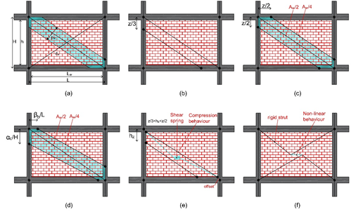
Figure 2. Marco-modeling approaches: (a) Holmes [10] single strut, (b) [11] two-strut approach, (c) Chrisostomou et al. [18] three-strut approach, (d) El-Dakhakhni et al. [19] three-strut approach, (e) Crisafulli [3] macro-model, (f) Furtado et al. [20] macro-model.
Presently, research is almost totally focused on the use of single or multiple equivalent diagonal strut models, used for the description of the seismic behavior of the reinforced concrete frames, but also on the derivation of constitutive laws that simulate in the most accurate way possible the main phases of damage that characterize the behavior of the infill wall panels. Among these, Noh [21] and Huang [22] have proposed formulas to derive the main parameters that characterize the response of the monotonous and cyclic behavior of the infill panels, in both cases reinforcing the use of the equivalent strut. In these two cases, a multilinear constitutive law based on the pinching material model proposed by Lowes [23] is taken into account to schematize the degradation of strength and stiffness due to progressive damage. Although this constitutive model requires a significant number of parameters, in particular to describe the cyclic response, it allows us to simulate in a satisfactory way the response of the infill panels.
2.2. Suggested Parameters for Macro-Models
As previously indicated, Polyakov [8] uses macro-models and proposes an equivalent diagonal strut system in order to consider the effect of masonry infill panels. However, it is necessary to estimate the equivalent strut width within this numerical analysis framework. Directly related to Polyakov’s proposal, Holmes [10] provides the first expression (Equation (1)) which determines the equivalent diagonal width of the strut:
|
bw/dw = 0.33, |
(1) |
where bw and dw are the strut width and length, respectively. Moreover, Stafford Smith [10] reinforces and specifies that the strut width must be between 0.10 and 0.25 times the diagonal length of the panel and also suggests an equation (Equation (2)) to calculate the related panel-to-frame-stiffness parameter:
|
λ = ∜((Ewϑ∙tw∙sin(2ϑ))/(4∙Ec∙Ic∙hw)), |
(2) |
where Ewϑ is the elastic modulus of the masonry panel in the diagonal direction, tw is the thickness of the infill panel, EcIc is the bending stiffness of the columns of the surrounding frame, hw is the height of the panel and ϑ is the angle related with the aspect ratio of the panel (hw/Lw) defined according to Equation (3):
|
ϑ = tan−1∙(hw/Lw), |
(3) |
where Lw is the length of the infill panel. High values of ϑ indicate that the surrounding frame is less rigid than the infill panel. Subsequently, other studies suggest equations to estimate the equivalent strut width. Mainstone [13] indicates two empirical expressions, Equations (4) and (5), based on analytical and experimental tests on various steel frames infilled with a masonry panel. As mentioned, Equation (4) has also been proposed in FEMA-306 [14].
|
bw/dw = 0.16∙(λh)−0.3, |
(4) |
|
bw/dw = 0.175∙(λh)−0.4, |
(5) |
Furthermore, Liauw and Kwan [24] in turn suggest a semi-empirical expression (Equation (6)), assuming 25° ≤ ϑ ≤ 50°, based on tests of infilled steel frames, used to calculate the equivalent width strut:
|
bw/dw = 0.95∙sin(2ϑ)/2∙√λh, |
(6) |
In Bertoldi [25], the width strut (Equation (7)) is defined by two coefficients (K1 and K2), which are defined as a function of λh.
|
bw/dw=K1/λh + K2; {(K1 = 1.300, K2 = −0.178; if λh < 3.14; K1 = 0.707, K2 = −0.010; if 3.14 < λh < 7.85; K1 = 0.470, K2 = −0.040; if λh > 7.85}, |
(7) |
Decanini and Fantin [26] suggest two families of equations (Equation (8)) to be used on the basis of the state of damage of the infill panels examined. The formulas were obtained through experimental tests on reinforced concrete masonry frames under lateral load.
|
Uncracked: {(0.085 + 0.748/λ)∙dw; if λh < 7.85), (0.130 + 0.393/λ)∙dw; if λh < 7.85)} Cracked: {(0.010 + 0.707/λ)∙dw; if λh < 7.85), (0.040 + 0.470/λ)∙dw; if λh < 7.85)}, |
(8) |
Another equation (Equation (9)) was proposed by Paulay and Priestley [23].
|
bw/dw = 0.25, |
(9) |
It is important to note that these values are in perfect line with what was asserted by Mainstone and Holmes; in fact, they are included between the lower limit value proposed by Mainstone [13] and the upper limit value presented by Holmes [10]. Furthermore, the value proposed by Paulay and Priestley [27] corresponds to the upper limit value of the range proposed by Stafford Smith [11]. Papia [28] proposed Equation (10) to evaluate the width of the strut on the basis of the Poisson’s ratio (c, β), the vertical load (k) and the geometric parameter (z):
|
bw/dw = kc/(z∙(λ*)β, |
(10) |
where, in particular, λ* is dimensionless, given by Equation (11), to estimate the relative panel-to-frame-stiffness parameter.
|
λ*=(Ewϑ∙tw∙h)/(Ec∙Ac)∙(h2/L2 + (Ac∙L)/(4∙Ab∙h)), |
(11) |
2.3. Constitutive Law for the Infill Masonry Wall
For elaborate nonlinear analyses of reinforced concrete frames filled with masonry, it is essential to use an adequate constitutive law that describes the behavior in the plane of the equivalent strut. The constitutive law for an equivalent strut is generally described using a multilinear relationship obtained and derived from experimental data as a backbone to simulate both the monotone and cyclic response of the panel. Four constitutive laws present in the literature are set out and described below, two of which concern very recent studies: Bertoldi [25], De Risi [29], Panagiotakos and Fardis [6] and Huang [22].
Bertoldi’s model [25] uses a four-ramification dorsal curve for the lateral force-displacement (F–Δ) relationship. The primary ascending branch represents the noncracked behavior up to the primary crack, followed by the second branch corresponding to the post-cracking behavior up to the event of maximum resistance, called peak strength (Fpeak). The third descending ramification of the dorsal curve defines the deterioration of post-peak resistance down to residual resistance (Fres). The fourth branch is horizontal and identifies the residual resistance of the infill panel. The parameters necessary to derive the proposed model are the equivalent strut width (bw), the secant stiffness at the entire cracking phase (Ksec), and therefore the peak resistance of the infill panel (Fpeak). All parameters are often defined as a function of the geometric and mechanical characteristics of the infill panel and therefore of the reinforced concrete frame that houses them.
The strong point of the model suggested by Bertoldi [25] is to estimate, predict and report clearly the most probable failure mode that the infill panel undergoes and highlights. In fact, the maximum resistance of the panel depends on the expected failure mode defined, again on the basis of the mechanical properties of the infill, and corresponds to the minimum of four failure modes. In particular, the peak force (Fpeak) is calculated considering four possible failure modes and therefore the corresponding failure stresses (Figure 3a).
Another constitutive model that is often employed by researchers is the modified version of the constitutive law originally proposed by Panagiotakos and Fardis [7]. In fact, within the original model, the dorsal curve is represented by four branches. In this case, the structure is composed of four branches and takes into account various states of stress: (a) initial behavior of the noncracked panel; (b) post-cracked linear response, characterized by a reduction in lateral stiffness thanks to the detachment of the infill from the containment frame; (c) post-peak softening response; (d) achievement of the residual axial resistance at a given displacement value. The model of Panagiotakos and Fardis [7] is widespread and widely used for engineering applications. It was initially obtained following the execution of 10 experimental tests performed on reinforced concrete frames filled with perforated masonry bricks that showed exactly a diagonal type break (Figure 3c).
From these starting data, supported by the analysis of an oversized database of masonry infill walls made with hollow bricks collected to be representative of the Mediterranean building heritage, recently De Risi [29] used and then modified the values of the lateral response in order to resize the dispersion with respect to the assembled database. In particular, the crack resistance (Fcr) and the maximum force (Fmax), the initial noncracked stiffness (K0), the stiffness ratio (K0/Ksec) and therefore the softening-peak stiffness ratios (Kdeg/Ksec) are changed.
The modification proposed by De Risi [29] significantly reduces the CoV values for the tests performed on hollow bricks with reference to the first formulation of Panagiotakos and Fardis [7]. This aspect is very important and demonstrates the accuracy of the proposed model, i.e., the average relative error of the backbone curve is 3% lower for all required parameters. Again, regarding the model suggested by De Risi [29], the primary branch corresponds to the elastic behavior up to cracking, and it is characterized by the initial noncracked stiffness (K0), assumed to be adequate to 2.8 times the Mainstone stiffness (KMS) (Figure 3b).
An interesting and very recent study is the one proposed by Huang [22] in suggesting the use of a dorsal curve calibrated also in this case on experimental results. In fact, as in the case of De Risi [29], the authors have collected a database of 264 tests performed on masonry infilled frames. Database analysis supported the proposing of an empirical model to estimate the parameters of the backbone curve for the equivalent diagonal strut. The major difference between the De Risi [29] and Huang [22] model is in the way the peak curve is obtained and differentiated; in particular, De Risi [29] started from the proposal of Panagiotakos and Fardis [6] and modified the existing semi-empirical formulations in order to reduce the dispersion with respect to their database. Instead, Huang [22] proposes empirical equations that, for the first time, correlate the different parameters of the load-bearing structure with the geometric and material properties of the buffered frame using multivariate multivariate analysis. During this study, only the median values of the backbone parameters were adopted (Figure 3d).
Unlike the work of Bertoldi [25] and De Risi [29], which provide the force-displacement curve for the equivalent strut, Huang [23] proposes formulations in terms of axial force deformation (F, Δ) for the infill strut [30,31].
 (a) (b) (c) (d)
Figure 3. Multilinear relationship models for the infill masonry panel proposed by (a) Bertoldi et al. [25]; (b) De Risi et al. [29]; (c) Panagiotokas et al. [7]; (d) Huang et al. 22].
3. Evaluation of the Capacity of Nonstructural Elements
Often the design of nonstructural elements is carried out by manufacturers considering only their main function, the loads deriving from their use and gravitational loads, neglecting the effects of exceptional actions such as earthquakes.
Even when product standards are available, there are few nonstructural elements for which the seismic problem is resolved at a regulatory level. As a consequence of this insufficiency of information, numerous past seismic events, even of low intensity, have brought to light performance deficiencies, highlighting how the collapse of nonstructural elements can be a source of risks for the occupants, of important service interruptions of buildings and of huge economic losses. Recognizing the importance and value of nonstructural elements, the regulatory bodies have for some years intensified the production of documents dedicated to classes of nonstructural elements or specific elements, the result of experimental and numerical research conducted.
3.1. Types of Assessment of Bearing Capacity of Nonstructural Elements
Regarding the Italian territory, the main regulatory reference is the Ministerial Decree of 17 January 2018—“Technical Standards for Construction” (NTC18 [2]) which defines, also for nonstructural elements and systems, the minimum performance targets. In §7.2.3, the NTC18 define nonstructural elements as “(.) those with stiffness, resistance and mass such as to significantly influence the structural response and those that, while not influencing the structural response, are equally significant for the safety and/or safety of people (.)”.
In the Italian and European context, the standard, normative references (cogent) regarding nonstructural elements are in fact often lacking or absent. However, extending the bibliographic research effort, one can find various international standards, both general and dedicated to specific types of nonstructural elements, thanks to which it is possible to evaluate the seismic capacity of these components.
Depending on the type of nonstructural element, the rules allow us to proceed with different, alternative or complementary approaches to each other. In general, the permitted evaluation methods can be based on numerical analyses, such as classifications through experimental tests or verifications based on past experience (in the event that similar nonstructural elements have been subjected to seismic actions during past events).
3.2. The Floor Spectra
The demand for acceleration on non-load-bearing elements (masonry infills) installed at different building heights is assessed using simplified methods in the actual regulations, although in these cases, the use of simplified methods is recommended. Recent seismic events have shown how current calculation methods can lead to completely incorrect assessments of damage to these components, so it is considered necessary to review these methods in order to take a further step in the definition design of structure. In current design practice, ordinary reinforced concrete frame buildings exposed to seismic action are usually calculated using a linear structural model and equivalent static or dynamic multimodal analysis with response spectrum. Concrete buildings are generally achieved by neglecting the stiffness and resistance of nonstructural elements such as infills and partitions, which are only taken into account because of their weight and mass contribution.
In current years, the work of many researchers has been directed to the definition of simplified methodologies which can be capable of faithfully reproducing the seismic demand on nonstructural elements through comparing the floor spectra.
A study conducted by Sullivan [32] highlighted how many instances, the formulations proposed through the regulatory codes are not appropriate for the right assessment of plan accelerations. Sullivan [32] argues that the spectral amplification strongly relies upon at the damping of nonstructural components; in fact, this issue is not always taken under consideration in any of the primary actual regulatory codes. Another very important aspect concerns the influence of the superior modes in the dynamic response; the Eurocode provides a formulation dependent only on the first natural mode of vibration of the structure; however, in many structures, such as those characterized by a significant number of floors, the influence of the superior modes cannot be neglected. The equal issues had been highlighted in a study performed by Medina [33], wherein the floor spectra for frames of various heights had been evaluated considering the elastic and nonlinear behavior of the structure; this research is concluded through demonstrating the unreliability of the actual formulations contained in the regulatory codes and proposes suggestions for the assessment of plan accelerations.
At a regulatory level, the formulation of floor spectra for the design of nonstructural elements was recently introduced with the explanatory circular of NTC2018 [2].
These spectra can be determined, starting from the accelerating seismic response of the structure at the considered altitude, in the simplified hypothesis that the structure can be assumed as a harmonic forcing for the nonstructural element, taking into account the amplifications due to the dynamic effects on the single nonstructural element, related to its period of oscillation and its damping coefficient as well as to the corresponding characteristics of the structure.
In particular, for Reinforced Concrete infilled frames, the same NTC2018 [2] present a simplified formulation, in the hypothesis of trend of structural accelerations linearly increasing with height. In this case, the maximum acceleration Sa (Ta) can be determined as
|
Sa(Ta) = α∙S∙(1 + z/H)∙[ap/1+(ap−1)∙(1−Ta/a∙T1)^2], ≥ α∙S, for Ta < a∙T1 |
(12) |
|
Sa(Ta) = α∙S∙(1 + z/H)∙ap, for a∙T1 < Ta < b∙T1 |
(13) |
|
Sa(Ta) = α∙S∙(1 + z/H)∙[ap/1 + (ap−1)∙(1−Ta/b∙T1)^2], ≥α∙S, for Ta ≥ b∙T1 |
(14) |
where
α = ratio between the maximum acceleration of the ground on the subsoil type A to be considered in the limit state in question and the acceleration due to gravity;
Ta = fundamental period of vibration of the nonstructural element;
T1 = fundamental period of vibration of the building in the considered direction;
z = height of the center of gravity of the nonstructural element measured from the foundation plane; equal to zero in structures with seismic isolation at the base;
H = the height of the construction measured from the foundation plane
S = coefficient that takes into account the category of subsoil and topographical conditions as reported in §3.2.3.2.1 [2]:
|
S = SS∙ST |
(15) |
SS = stratigraphic amplification coefficient
ST = topographical amplification coefficient
Please refer to chapters §3.2.3.2.1 [2] and §3.2.3.2.1 [2] of the standard for explanatory tables of ST and SS or parameters a, b, p defined in accordance with the fundamental vibration period.
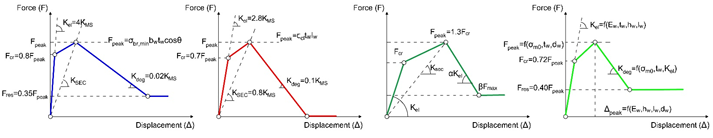
The floor spectra described in this way (Figure 4) are generally conservative for a wide range of periods, with particular regard to nonstructural elements having a period close to the fundamental period of construction.
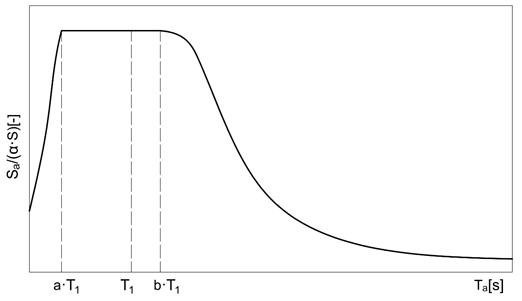
Figure 4. Proposed floor spectra built according to regulations.
Because the nonstructural elements subject to evaluation are generally not positioned on the ground, but rather in any other point of the building, the motion to refer to is that of the installation point, or motion on the ground. The spectra that can be calculated and referred to in the evaluation procedures are therefore the acceleration spectra at the plane.
Today’s structural design regulations, including NTC18 [2] and EC8 [34], use precisely the floor acceleration spectrum to estimate the response of an installed nonstructural element to a generic share.
In general, the floor spectra can do the following:
- consider the characteristics of dynamic amplification of the main structure, typically present around its own periods of vibration and variables along the height of the building;
- consider the viscous and hysteretic damping, possibly present when referring to the ultimate limit states, of the main structure hosting the nonstructural elements;
- consider the resonance effects between the main structure and nonstructural elements;
- consider the viscous damping of nonstructural elements;
- consider the hysteretic damping of the nonstructural elements linked to any plasticization caused by the earthquake.
It should be noted that the reduction in the ordinates of the plane spectrum, generated by the plastic hysteretic behavior of the nonstructural elements, it should be considered only in some applications. For example, this reduction must be considered in the calculation of the maximum stresses with which to dimension the connection system of the nonstructural component to the structure.
4. Conclusions
The fundamental role played by nonstructural elements in terms of safety and maintenance of functionality of buildings is now unanimously recognized. Against this, national and international standards have been developed as useful tools for designers, manufacturers and installers to ensure adequate seismic-behavior of nonstructural elements. In Italy, the main reference for construction is the Ministerial Decree January 17, 2018—“Technical Standards for Construction” (NTC18) [2] which defines, even for nonstructural elements, the minimum performance targets and the roles and responsibilities of the actors involved. Clearly, the fulfillment of the requirements required cannot be separated from the correct evaluation both of the seismic input and of the performance of nonstructural elements. For most of the nonstructural elements, the seismic input must be specified through suitable floor spectra. As discussed, these can be rigorously calculated through validated simplified methods. It should be recognized that the proposed methods greatly reduce the computational cost, if compared with methods that exploit nonlinear analyses. However, it is still necessary to have structural models sufficiently accurate to be able to grasp the dynamic behavior of the main structure. On the other hand, it is difficult to figure out a method that can solve the problem of floor spectra regardless of the modal parameters of the structure.
All this considered, there is no doubt that the infill panels influence the behavior of the structural complex, but this influence can have a double nature: on one side, there are beneficial effects linked to the increase in the resistance and dissipative capacity of the system; on the other side, we can have fragile collapses and greater stresses both locally and globally. It should also be remembered that an increase in resistance does not always correspond to an improvement in structural behavior. To improve the seismic response of a structure, either its resistance or ductility are increased. In general, it is better to increase ductility because it guarantees greater safety margins. However, it is always essential to verify whether the increase in stiffness caused by the infill panels do or do not have a positive effect on the seismic behavior of the structure. Predicting these effects is not easy because they are associated with variables characterized by a high degree of uncertainty, including the following:
- the mechanical and behavioral properties of the masonry;
- the constraint conditions that exist between the confinement frame and the infill;
- the changes to which these elements are subject during the useful life of the work;
- the ways in which they were created, therefore from the competence of the workers;
- the degree of damage connected to the seismic event;
For these reasons, acting in favor of safety, it is necessary to consider only the negative effects linked to the presence of infill masonry walls. This must be done through simple and easily manageable calculations and structural models, able to reproduce in the environment the structural behavior linked to the interaction between the load-bearing structure (the reinforced concrete frame) and the secondary elements (the infill panels) as faithfully as possible.
In conclusion, it is evident that the influence of the infills on the seismic behavior of the structure in which they are inserted is absolutely not negligible. Both the Italian and the European legislation do not give particular support to the designers in the sector who are aware that the effects that infill masonry panels have on the planned structure must be taken into account. Nevertheless, the designers are not sufficiently supported by the rules for an objective evaluation of these effects. In essence, the regulations highlight the aspects that must be treated with particular attention, but they do not specify the methods of analysis and verification that must be adopted.
This regulatory gap is linked to the difficulty of modeling, within current calculation software, infill wall, the behavior of which is highly uncertain because it is influenced by numerous factors that are difficult to evaluate experimentally. To be effective, these models should not require excessively long data processing times. To achieve this goal, the use of macromodels such as those here described becomes indispensable because once they are properly calibrated, they are able to reproduce in a certainly more faithful way the seismic behavior of the secondary masonry elements towards the structure in which they are inserted.