Your browser does not fully support modern features. Please upgrade for a smoother experience.
Please note this is an old version of this entry, which may differ significantly from the current revision.
Subjects:
Physics, Applied
Radiographic imaging with muons, also called Muography, is based on the measurement of the absorption of muons, generated by the interaction of cosmic rays with the earth’s atmosphere, in matter. Muons are elementary particles with high penetrating power, a characteristic that makes them capable of crossing bodies of dimensions of the order of hundreds of meters.
- muography
- radiographic imaging
- Muon
- 3D reconstruction technique
- Machine Learning
- Muons spectra modelling
1. A Brief Overview
The muographic methodology is used for imaging the interior of a body, exploiting the high penetration capacity of cosmic muons [1][2][3][4][5][6]. Two different techniques are currently referred to as Muography and used to measure the density of the target object: absorption Muography and deviation Muography. Deviation Muography is usually used for the detection of high density materials in small size objects and is based on the multiple Coulomb scattering experienced by muons when passing through matter [7][8][9][10].
In absorption Muography, the attenuation of the muon flux is used to measure the absorption of muons into matter. The measured number of muons is used to obtain a two-dimensional scatter plot of the density of a target volume. Large volumes can be imaged with this technique as sensed by the pioneering works provided by George [11] in 1955, who obtained a measurement of the overburden of a tunnel, and by Alvarez [12], who first provided a muograph of the Chefren pyramid. The applications of muography in the volcanological field [13][14][15][16][17][18][19][20] are very frequent, and from the 1990s onwards they have contributed to the revival of the methodology. Recent works in absorption Muography concern the study of the pyramid of Cheops (Kufhu) [21] and other cultural heritages [22], the discovery of cavities inside a hill [23][24], the exploration of archaeological sites [25][26], and the imaging of tidewater glaciers [27] and of nuclear reactors [28][29][30]. Absorption Muography is nowadays used in highly disparate fields, with techniques that differ not only on the basis of the size and density of the objects, but also according to the setup of the detectors and the technologies used for their realization and performance optimization. Detectors normally used in the muographic field derive directly, or in any case, are adapted from those used for the detection of ionizing radiation in high energy physics. Detailed descriptions of the detection technologies used in muon radiography can be found in [1][2][3].
Natural muons are generated from the so-called primary cosmic radiation. The primary cosmic rays are mainly composed of stable charged particles and of nuclei with lifetimes of millions of years. Once this radiation reaches the Earth atmosphere, it interacts with the atoms all along the stratosphere, the part of Earth’s atmosphere that extends for 40 km from 10 km above sea level and below, producing showers of new particles called secondary cosmic rays. At sea level, the secondary charged radiation is mainly composed of electrons, positrons, muons and protons. Muons are the most abundant component of secondary radiation.
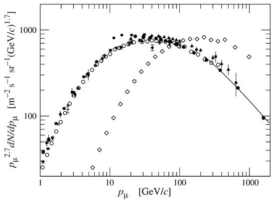
The decay of intermediate mesons π and K is such to generate high energy muons, which can reach several tens of TeV and more. They are leptons, ∼200 times heavier than the electrons, with a large energy spectrum and high penetrating power. The fraction of muons capable of crossing a few thousand meters of matter increases in the range of the angles close to the horizon. Figure 1 shows the fluxes of vertical and quasi-horizontal muons; it shows an upper shift in the energy of the flux spectrum at 75∘ with respect to the flux at 0∘, as a function of the muon momentum and, hence, of their energy. This means that the horizontal muon flux is more energetic than the vertical one. However, the latter has a higher average intensity than the former.
2. The Technique of Radiographic Imaging with Muons
Muon radiography (Muography) is a technique based on the measurement of the absorption of cosmic muons in matter for the direct imaging of large structures. A muon detector looking at a target region detects the muons, tracks their routes and counts them. This allows the average density along the paths traveled by the muons to be calculated. In particular, vertical detectors are often required in some muographic applications due to the need to exploit the near horizontal muon flux, which is characterized by the high energy required to penetrate up to a few kilometers of matter.
In ideal conditions, the transmission as a function of the zenith and azimuth angles, is defined as
 (1)
(1)that is the fraction between the number N(θ,φ) of muons that pass through the target and the number Nexp(θ,φ) of expected ones without the target. The expected number of muons can be evaluated with Monte Carlo simulation or, alternatively, another procedure can be performed with a free sky data taking. The latter measurement has the advantage of including the detector efficiency factor, while in a Monte Carlo simulation it must be a priori well known. The measurement of the transmission in the free sky data acquisition involves two different measurements, in different time, so that the detector points to the target region and then, after it has been moved, to the open sky for the free sky data acquisition. The Equation (1) becomes the measured transmission

in which
-
ϵfs is the efficiency term of the detector in free sky data taking
-
ϵ is the efficiency term of the detector in the data taking
-
tfs is the time taken to perform the free sky data taking
-
t is the time taken to perform the data taking
-
Nm(θ,φ) is the number of detected muons passed through the target
-
Nfs(θ,φ) is the number of muons counted during the free sky run
Where the ratio ttfs=1, if t is normalized to the free sky data acquisition time. The efficiency terms can differ even if the detector used in the two different data taking is the same; in general, the efficiency term takes into account factors concerning the detector that affect both the acquisition and the analysis of the data.
On the other hand, we can calculate the expected transmission by means of the intensity i(θ,φ,Eμ) as a function of the muon energy Eμ. By integrating this over all the energy spectrum we have

where E is, in general, a function of the angular coordinates and of the density of the material passed by the muon and represents the minimum energy that muons must have in order to be detected, therefore without being previously absorbed by the material through which they pass. We can compute the expected transmission as the ratio between the muon flux through a material of density and the muon flux in open sky, hence

with Emin and E0 being the minimum energy in the selected angular bin (θ,φ) of the target region and the open sky, respectively. A digital terrain model (DTM) of the target region is used to calculate the muon flux through it.
The relative transmission, whose scatter plot represents the muographic image, is given by

that reduces to the Equation (5) in the case in which the muon flux model is absolutely faithful to reality and normalized to the acquisition time, and the detector is faithfully reproduced with its efficiency in the process of calculating the expected flux.
Once the transmission map of the target has been measured, we can obtain the expected depth in kilometers water equivalent (kmwe), penetrated by muons at different zenith angles. Water constitutes an homogeneous medium, with unit density ρw by default, and the depth measured using water can be easily compared to inhomogeneous material [32].
The expected depth in kmwe can be evaluated with a simulation in GEANT4 [33]. In this case, the expected transmission, as a function of the different path length at different zenith angles, is the ratio between the number of the survived muons and the number of injected muons. The energy spectrum at different θ of the injected flux is the Equation (5) and the curves, parameterized by the zenith angle passed in a given volume of material of known density ρm. If we assume the density of the water ρm=1, the real path length is equal to the depth in kilometers water equivalent penetrated by muons.
Once all values of the transmission in every angular bin have been measured, we obtain the related map of path length xθ=Λθ. Since xθ=Lθρ and being Lθ the thickness of matter, of unknown density ρ, traversed by the muon at angle θ, we have

where Lθ is taken as in the DTM.
3. The 3D Reconstruction Technique and Expected Performance
By combining multiple radiographic images taken from different points of view, as successfully demonstrated in [34], it is possible to reconstruct an object seen under different angles. The main limit of the technique concerns the availability of places where detectors can be installed. Sometimes it may be impossible to have a large number of points of view, and above all it may not be possible to surround the target region. In addition, it must be borne in mind that due to the origin of the muon flux, the target region must always be at a higher height than that of the detector.
The reconstruction of a body with different density inserted in the target region takes radiographic images from each point of view, and identifies the signals belonging to each of them, which are in angular correspondence with each other. So, defining a grid of points in a cubic volume that encloses the region where the density discontinuity is found, according to the angular ranges, a point was considered to be located inside a discontinuity region if in each of the three radiographic images it corresponded to a direction lying inside a signal cluster.
The procedure was tested by simulating the presence of a spherical cavity with 6 m diameter, seen by three points of view as in Figure 1. The result is shown in Figure 1 as seen by the detector C. The blue dots represent an ensemble of points distributed on the grid and located inside the cavity. The points satisfying the intersection criterion are denoted by red dots.
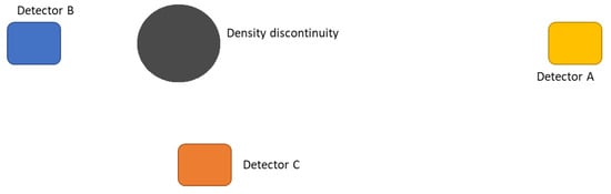
Figure 1. Schematic of the simulated scenario. Detectors (not in scale) placed in the positions A, B and C.
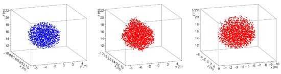
Figure 2. A spherical cavity (left) and its 3D reconstruction as seen from the observation point of the detectors C (center) and B (right) as in [34].
As it can be seen in Figure 2, the reconstructed cavity is deformed by the stereographic projection. This overestimates the size of the discontinuity, which appears to be larger in those directions in which there are no points of view. The origin of the observed halo is due to the fact that the criterion is satisfied also by points that, in a projection, appear in the shadow of the cavity, rather than inside. It is evident that the onset of this deformation in the reconstruction can be reduced, but not eliminated, by increasing the number of observation points. In any case, we must bear in mind that it is not possible to observe the target region from heights above the discontinuity zone.
This entry is adapted from the peer-reviewed paper 10.3390/jimaging7120253
References
- Bonomi, G.; Checchia, P.; D’Errico, M.; Pagano, D.; Saracino, G. Applications of cosmic-ray muons. Prog. Part. Nucl. Phys. 2020, 112, 103768.
- Bonechi, L.; D’Alessandro, R.; Giammanco, A. Atmospheric muons as an imaging tool. Rev. Phys. 2020, 5, 100038.
- Lechmann, A.; Mair, D.; Ariga, A.; Ariga, T.; Ereditato, A.; Nishiyama, R.; Pistillo, C.; Scampoli, P.; Schlunegger, F.; Vladymyrov, M. Muon tomography in geoscientific research—A guide to best practice. Earth-Sci. Rev. 2021, 222, 103842.
- Zhang, Z.X.; Enqvist, T.; Holma, M.; Kuusiniemi, P. Muography and Its Potential Applications to Mining and Rock Engineering. Rock Mech. Rock Eng. 2020, 53, 4893–4907.
- Kaiser, R. Muography: Overview and future directions. Philos. Trans. R. Soc. A Math. Phys. Eng. Sci. 2019, 377, 20180049.
- Procureur, S. Muon imaging: Principles, technologies and applications. Nucl. Instr. Methods Phys. Res. Sect. A Accel. Spectr. Detect. Assoc. Equip. 2018, 878, 169–179.
- Morris, C.L.; Bacon, J.; Borozdin, K.; Fabritius, J.; Miyadera, H.; Perry, J.; Sugita, T. Horizontal cosmic ray muon radiography for imaging nuclear threats. Nucl. Instr. Methods Phys. Res. Sect. B Beam Interact. Mater. Atoms. 2014, 330, 42–46.
- Mahon, D.; Clarkson, A.; Gardner, S.; Ireland, D.; Jebali, R.; Kaiser, R.; Ryan, M.; Shearer, C.; Yang, G. First-of-a-kind muography for nuclear waste characterization. Philos. Trans. R. Soc. A Math. Phys. Eng. Sci. 2019, 377, 20180048.
- Vanini, S.; Calvini, P.; Checchia, P.; Rigoni Garola, A.; Klinger, J.; Zumerle, G.; Bonomi, G.; Donzella, A.; Zenoni, A. Muography of different structures using muon scattering and absorption algorithms. Philos. Trans. R. Soc. A Math. Phys. Eng. Sci. 2019, 377, 20180051.
- Lo Presti, D.; Antonuccio, V.; Bandieramonte, M.; Becciani, U.; Belluomo, F.; Belluso, M.; Billotta, S.; Blancato, A.; Bonanno, D.; Bonanno, G.; et al. Design of a large area tomograph to search for high-Z materials inside containers by cosmic muons. In Proceedings of the 2012 IEEE Nuclear Science Symposium and Medical Imaging Conference Record (NSS/MIC), Anaheim, CA, USA, 27 October–3 November 2012; pp. 5–8.
- George, E.P. Cosmic rays measure overburden of tunnel. Commonwealth Eng. 1955, 1995, 455–457.
- Alvarez, L.W.; Anderson, J.A.; Bedwei, F.E.; Burkhard, J.; Fakhri, A.; Girgis, A.; Goneid, A.; Hassan, F.; Iverson, D.; Lynch, G.; et al. Search for Hidden Chambers in the Pyramids. Science 1970, 167, 832–839.
- Tanaka, H.K.; Nakano, T.; Takahashi, S.; Yoshida, J.; Takeo, M.; Oikawa, J.; Ohminato, T.; Aoki, Y.; Koyama, E.; Tsuji, H.; et al. High resolution imaging in the inhomogeneous crust with cosmic-ray muon radiography: The density structure below the volcanic crater floor of Mt. Asama, Japan. Earth Planet. Sci. Lett. 2007, 263, 104–113.
- Cârloganu, C.; Niess, V.; Béné, S.; Busato, E.; Dupieux, P.; Fehr, F.; Gay, P.; Miallier, D.; Vulpescu, B.; Boivin, P.; et al. Towards a muon radiography of the Puy de Dôme. Geosci. Instr. Methods Data Syst. 2013, 2, 55–60.
- Noli, P.; Ambrosino, F.; Bonechi, L.; Bross, A.; Cimmino, L.; D’alessandro, R.; Masone, V.; Mori, N.; Passeggio, G.; Pla-Dalmau, A.; et al. Muography of the puy de dôme. Ann. Geophys. 2017, 60.
- Oláh, L.; Tanaka, H.K.M.; Hamar, G.; Varga, D. Investigation of the limits of high-definition muography for observation of Mt Sakurajima. Philos. Trans. R. Soc. A Math. Phys. Eng. Sci. 2019, 377, 20180135.
- Tioukov, V.; Alexandrov, A.; Bozza, C.; Consiglio, L.; D’Ambrosio, N.; De Lellis, G.; De Sio, C.; Giudicepietro, F.; Macedonio, G.; Miyamoto, S.; et al. First muography of Stromboli volcano. Sci. Rep. 2019, 9, 6695.
- D’Errico, M.; Ambrosino, F.; Baccani, G.; Bonechi, L.; Bross, A.; Bongi, M.; Caputo, A.; Ciaranfi, R.; Cimmino, L.; Ciulli, V.; et al. Muon radiography applied to volcanoes imaging: The MURAVES experiment at Mt. Vesuvius. JINST 2020, 15, C03014.
- Vesga-Ramirez, A.; Porta, D.S.; Rodriguez, J.P.; Sanabria-Gomez, J.; Valencia-Otero, M.; Sarmiento-Cano, C.; Suarez-Duran, M.; Asorey, H.; Nunez, L. Muon Tomography sites for Colombian volcanoes. Ann. Geophys. 2020, 63.
- Tanaka, H.K.M. Japanese volcanoes visualized with muography. Philos. Trans. R. Soc. A Math. Phys. Eng. Sci. 2019, 377, 20180142.
- Morishima, K.; Kuno, M.; Nishio, A.; Kitagawa, N.; Manabe, Y.; Moto, M.; Takasaki, F.; Fujii, H.; Satoh, K.; Kodama, H.; et al. Discovery of a big void in Khufu’s Pyramid by observation of cosmic-ray muons. Nature 2017, 552, 386–390.
- Guardincerri, E.; Durham, J.; Morris, C.; Bacon, J.; Daughton, T.; Fellows, S.; Morley, D.; Johnson, O.; Plaud-Ramos, K.; Poulson, D.; et al. Imaging the inside of thick structures using cosmic rays. AIP Adv. 2016, 6, 015213.
- Saracino, G.; Amato, L.; Ambrosino, F.; Antonucci, G.; Bonechi, L.; Cimmino, L.; Consiglio, L.; D’Alessandro, R.; De Luzio, E.; Minin, G.; et al. Imaging of underground cavities with cosmic-ray muons from observations at Mt. Echia (Naples). Sci. Rep. 2017, 7, 1181.
- D’Errico, M. Muography applied to archaeology: Search and 3D reconstruction of hidden cavities. Nuovo Cimento Della Soc. Ital. Fis. C 2020, 43, 1–10.
- Baccani, G.; Bonechi, L.; Bongi, M.; Brocchini, D.; Casagli, N.; Ciaranfi, R.; Cimmino, L.; Ciulli, V.; D’Alessandro, R.; Ventisette, C.; et al. Muon Radiography of Ancient Mines: The San Silvestro Archaeo-Mining Park (Campiglia Marittima, Tuscany). Universe 2019, 5, 34.
- Menichelli, M.; Ansoldi, S.; Bari, M.; Basset, M.; Battiston, R.; Blasko, S.; Coren, F.; Fiori, E.; Giannini, G.; Iugovaz, D.; et al. A scintillating fibres tracker detector for archaeological applications. Nucl. Instr. Methods Phys. Res. Sect. A Accel. Spectr. Detect. Assoc. Equip. 2007, 572, 262–265.
- Tanaka, H.; Aichi, M.; Bozza, C.; Coniglione, R.; Gluyas, J.; Hayashi, N.; Holma, M.; Kamoshida, O.; Kato, Y.; Kin, T.; et al. First results of undersea muography with the Tokyo-Bay Seafloor Hyper-Kilometric Submarine Deep Detector. Sci. Rep. 2021, 11, 19485.
- Perry, J.; Azzouz, M.; Bacon, J.; Borozdin, K.; Chen, E.; Fabritius, J., II; Milner, E.; Miyadera, H.; Morris, C.; Roybal, J.; et al. Imaging a nuclear reactor using cosmic ray muons. J. Appl. Phys. 2013, 113, 184909.
- Miyadera, H.; Borozdin, K.; Greene, S.; Lukić, Z.; Masuda, K.; Milner, E.; Morris, C.; Perry, J. Imaging Fukushima Daiichi reactors with muons. AIP Adv. 2013, 3, 052133.
- Fujii, H.; Hara, K.; Hayashi, K.; Kakuno, H.; Kodama, H.; Nagamine, K.; Sato, K.; Kim, S.H.; Suzuki, A.; Sumiyoshi, T.; et al. Investigation of the unit-1 nuclear reactor of Fukushima Daiichi by cosmic muon radiography. Prog. Theor. Exp. Phys. 2020, 2020, 043C02.
- Patrignani, C. Review of Particle Physics. Chin. Phys. C 2016, 40, 100001.
- Hayakawa, S. Cosmic Ray Physics; Wiley, Interscience: New York, NY, USA, 1969.
- Agostinelli, S.; Allison, J.; Amako, K.; Apostolakis, J.; Araujo, H.; Arce, P.; Asai, M.; Axen, D.; Banerjee, S.; Barrand, G.; et al. Geant4—A simulation toolkit. Nucl. Instr. Methods Phys. Res. Sect. A Accel. Spectr. Detect. Assoc. Equip. 2003, 506, 250–303.
- Cimmino, L.; Baccani, G.; Noli, P.; Amato, L.; Ambrosino, F.; Bonechi, L.; Bongi, M.; Ciulli, V.; D’Alessandro, R.; D’Errico, M.; et al. 3D Muography for the Search of Hidden Cavities. Sci. Rep. 2019, 9.
This entry is offline, you can click here to edit this entry!