Your browser does not fully support modern features. Please upgrade for a smoother experience.
Please note this is an old version of this entry, which may differ significantly from the current revision.
Subjects:
Agricultural Engineering
In recent years, with the rapid development of the flexible electronics industry, there is an urgent need for a large-area, multilayer, and high-production integrated manufacturing technology for scalable and flexible electronic products. To solve this technical demand, researchers have proposed and developed microtransfer printing technology, which picks up and prints inks in various material forms from the donor substrate to the target substrate, successfully realizing the integrated manufacturing of flexible electronic products.
- flexible electronics
- microtransfer printing
1. Kinetic Control Transfer Printing
Rogers et al. [1] were the first to propose a kinetically controlled transfer printing method. This method uses velocity to dynamically control the adhesion force switching between interfaces to achieve transfer printing, because of the adhesion characteristics of PDMS. The energy release rate Gstamp/filmcrit of the seal/ink interface depends on the layering speed ν, while the energy release rate Gstamp/filmcrit of the ink/target substrate interface is independent of velocity. The main process of kinetic control transfer is as follows: The ink is extracted from the donor substrate by using the adhesion characteristics of the seal through a relatively large stripping speed (about 10 cm/s, i.e., Gfilm/substratecrit<Gstamp/filmcrit [2]). The seal and ink are contacted with the target substrate, and the seal is extracted at a relatively small stripping speed (about 1 mm/s, i.e., Gfilm/substratecrit>Gstamp/filmcrit [2]). Additionally, the ink is transferred to the target substrate. Figure 1a,b shows the mechanical model diagrams of the extracting film and printing film processes. Feng et al. [2] regarded the seal/substrate interface separation as a steady-state crack propagation process. Figure 1c shows the schematic diagram of the seal interface separation when subjected to a vertical upward pull F. The energy release rate is
where G is the energy release rate, F is the tensile force, and w is the width of the seal. Formula (2) is the energy release rate of the seal/film interface, which is
where G0 is the critical energy release rate, ν is the stripping speed, ν0 is the reference stripping speed, and n is the scaling parameter determined during the experiment. Formula (2) applies to various stripping speed ranges, temperature ranges, metal/polymer interfaces, polymer/polymer interfaces, and so forth. Figure 1d shows a graph of the relationship between energy release rate and stripping speed, where νmax is the maximum stripping speed and ν is the critical stripping speed. The critical speed depends on the stiffness of the seal. Under the condition of determining the geometric dimension of the seal, the critical speed decreases with the decrease in the modulus of the seal [2]. Feng et al. [2] also studied the effect of temperature on the transfer printing structure, which found that low temperatures favored the extraction of the ink and high temperatures favored the transfer printing. Also explored is the discontinuous film, both discrete of distribution ink. The relation between average energy release rate and contact area is
where ƒ represents the contact area fraction (0 < ƒ < 1) of the seal/ink interface, where Gink/stamp(ν) is the energy release rate. Formula (3) shows that the adhesion strength between the seal/ink/target substrate interfaces is proportional to the contact area. Kim et al. [3] conducted a 90° stripping experiment on this basis and concluded that reducing the contact area was beneficial to improve the success rate of transfer printing. Figure 2a shows the relationship between the percentage of the seal contact area and the percentage of the successful transfer area. Jiang et al. [4] also conducted an experimental investigation and simulations on seal transfer printing Si tapes with different stripping speeds. It was found that the transfer printing efficiency increases with the increase in the stripping speed, but the transfer printing efficiency increases slowly when the stripping speed is greater than 100 mms−1. Figure 2b shows the optical image of the transferred Si tape under different stripping speeds of the PDMS seal, and Figure 2c shows a graph of transfer printing efficiency versus stripping speed in the simulation experiment. The simulation results are consistent with the experimental results.
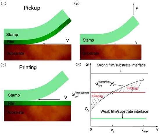
Figure 1. Kinetic control transfer printing process diagram. (a) Mechanical model diagram of the film extraction process (reproduced from [5]), (b) mechanical model diagram of the printing film process (reproduced from [5]), (c) schematic diagram of the separation of the seal under vertical upward pull F interface (reproduced from [5]), and (d) relationship between energy release rate and peeling speed (reproduced from [5]).
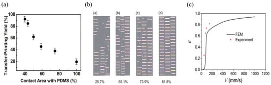
Figure 2. Kinetic control transfer printing principle. (a) The relationship between the percentage of the seal contact area and the percentage of the successful transfer printing area (reproduced from [3]), (b) optical image of transferred Si tape under different peeling speeds of the PDMS seal (reproduced from [4]), and (c) graph of transfer printing efficiency and peeling speed (reproduced from [4]).
Since the controllable range of bonding is narrow, in most situations, kinetic control transfer printing requires an adhesive to be applied above the target substrate to assist in the transfer printing process. However, this method cannot change the adhesive force of the seal and make the transfer printing process continuous, which greatly reduces the efficiency of the transfer printing. Kim et al. [6] found that by changing the design parameters of the seal and adjusting the stripping speed, the controllable range of adhesion strength can be effectively extended, and also high yield manufacturing can be achieved. Figure 3a,b shows graphs of the relationship between seal thickness and tensile force under different contact loads, L=10 mN, L=100 mN,L=800 mN, at the stripping speeds Vsep=2 μm/s and Vsep=500 μm/s, respectively. The results show that the stripping force is correlated with the critical interface contact area, and the thicknesses of the seal, contact load, and stripping speed are the main influencing factors. Liang et al. [7] established a tensile force model in which the stripping speed and pretightening force were considered. Finally, the relationship between stripping speed, pretightening force, and tensile force was studied. From Figure 3c, we can know that the tensile force increases with the increase in peeling speed at a certain preload. From Figure 3d, we can know that the tensile force increases with the increase in pretightening force at a certain stripping speed. It follows that a larger preload force should be applied during the transfer extraction phase, and a smaller preload force should be applied during the printing phase, which can play a significant role in improving the transfer printing output. Through analysis of the theoretical model and experimental data, the results show that the pretightening force at a large stripping speed has a greater influence on the tensile force than the pretightening force at a small stripping speed [7]. Figure 3e,f shows examples of transfer printing on cylindrical glass lenses and PET substrates using the kinetic control transfer printing method.
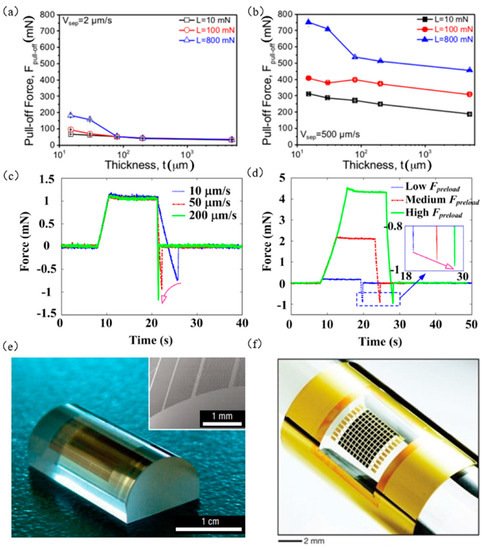
Figure 3. Kinetic transfer printing principles and examples. (a,b) The relationship between the thickness of the seal and the tensile force under different contact loads at different peeling speeds (reproduced from [6]), (c) the relationship between the pulling force and the peeling speed (reproduced from [7]), (d) the relationship between tension and preload (reproduced from [7]), (e) printed array formed on cylindrical glass lens (reproduced from [1]), and (f) flexible gallium arsenide solar cell array (reproduced from [8]).
The process of kinetic control transfer printing is simple and easy to operate, but the stripping speed control adhesion strength range is limited, the transfer printing is greatly restricted, and its durability depends on the preparation of the target substrate and the cleanness and flatness of the substrate surface. This method is also not applicable to target substrates of viscous materials. Therefore, its application is limited by different materials. Precise speed control is required during operation, which requires a speed control device to improve transfer printing efficiency, but greatly increases the cost of the transfer printing. Moreover, this transfer printing method has not produced an example of nanotransfer printing because the energy release rate is influenced by the contact area.
2. Laser Control Seal Temperature Transfer Printing
Saeidpourazar et al. [9] developed a laser-controlled seal temperature transfer printing technique by exploiting the differences in the thermodynamic parameters (coefficient of thermal expansion and thermal conductivity) of PDMS seals and inks. The specific process of this technology is shown in Figure 4a. The seal with a microstructure selectively picks up the ink on the donor substrate and then transfers the printing of the ink above the target substrate. Due to the transparency of the PDMS seal to the laser (805 nm), the pulsed laser glow focuses on the ink through the seal. The ink transmits heat to the PDMS seal through the seal/ink interface, raising the temperature of the ink and the seal. Due to the thermodynamic differences between the seal and the ink, finally, the seal/ink interface is layered to realize transfer printing. Li et al. [10][11] established the thermodynamic theoretical model shown in Figure 4a, which did not consider the influence of silicon wafer size. The relationship for the delamination time tdelamination seal/silicon interface is calculated as follows:
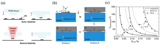
Figure 4. Laser-controlled seal temperature transfer printing technology. (a) Laser-controlled seal temperature transfer printing diagram (reproduced from [9]), (b) accurate interface fracture mechanics model diagram (reproduced from [12]), and (c) the peeling time scale rule of laser-controlled seal temperature transfer printing (reproduced from [12]).
In Formula (1),
where qtotal is the total heat of the seal/silicon interface irradiated by the pulsed laser, hsilicon and Lsilicon are the thickness and width of the silicon wafer, cPDMS and csilicon are the specific heat, ρPDMS and ρsilicon are the mass density, λPDMS is the thermal conductivity, αPDMS is the coefficient of thermal expansion, and μPDMS is the shear modulus and the adhesion strength of the interface γ. The thermodynamic model does not apply to smaller silicon wafer sizes. Gao et al. [12] considered the influence of silicon wafer size and established an accurate interfacial fracture mechanics model (as shown in Figure 4b), which was used to derive the composite stress intensity factor, interfacial energy release rate, and critical delamination time, which eventually coincided with the finite element calculations, as shown in Figure 4c.
Eisenhaure et al. [13] took advantage of the SMP materials, which are rigid when the polymer is below the transition temperature Tg and can increase the adhesion strength of the seal. By replacing the traditional PDMS seal with an SMP seal, there are more options for seal design, and the analytical formula of seal plane stress is obtained:
where E is the modulus of elasticity, L is the width of the seal, and γ0 is the adhesive strength. The finite element analysis is consistent with Formula (8), as shown in Figure 5a. They also compared the two seal surfaces (smooth seal surface and pyramid microstructure seal surface), which are more suitable for transfer printing. Figure 5b shows the relationship between the two types of seals and the plane stress at different stripping speeds. It is shown that the seal with a microstructure on the surface is more suitable for transfer printing.
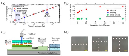
Figure 5. The principle of laser-controlled seal temperature transfer printing technology. (a) The relationship between the elastic modulus and the plane stress of the seal (reproduced from [13]), (b) the relationship between the two types of seals and the plane stress at different peeling speeds (reproduced from [13]), (c) laser programmable selective transfer printing equipment setup diagram (reproduced from [14]), and (d) examples of successful transfer printing of straight, cross, and T-shaped patterns (reproduced from [14]).
Feng et al. [14] developed a laser programmable selective transfer printing method that uses a stepper-motor-controlled precision platform to control the displacement of the target substrate and uses laser heating of the SMP seal to achieve a high conversion of the adhesion force. Figure 5c shows the setting diagram of laser programmable selective transfer printing equipment. Figure 5d shows examples of successful transfer printing of linear, cross, and T-shaped patterns. Song et al. [15] used SMP materials to design a seal with a circular cavity, with a metal layer on the upper surface of the cavity as a heat absorption layer, and closed the air inside the cavity with a film with a microstructure. The transfer printing process is shown in Figure 6a. Figure 6b shows the stress relationship diagram at different elevated temperatures. Kim et al. [16] prepared an SMP seal with a carbon black composite material (as shown in Figure 6c), which greatly improved the heat transfer rate by taking advantage of the material’s absorption of infrared laser light. At the same time, it also solves the limitation that the ink must be a laser-absorbing material for the laser transfer printing process and saves the complicated steps of calculating the laser power required for different ink materials and geometric shapes. Figure 6d shows an example of selective printing of gold-plated silicon wafers that do not absorb infrared laser ink.
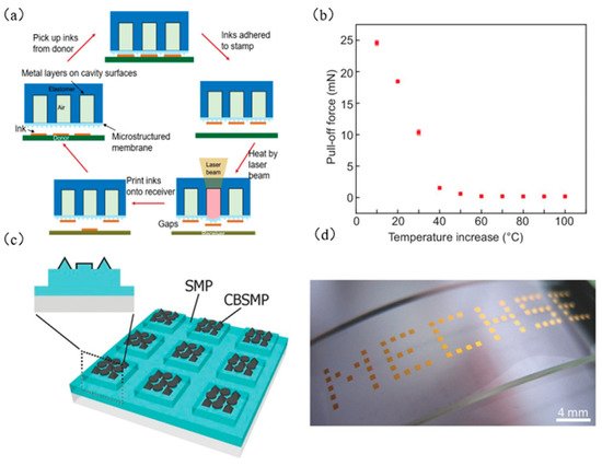
Figure 6. Laser-controlled seal temperature transfer printing technology process diagram and example. (a) Specific diagram of laser temperature control transfer printing technology for seal with cavity (reproduced from [17]), (b) stress relationship diagram at different elevated temperatures (reproduced from [17]), (c) SMP seal design drawing with carbon black composite material (reproduced from [16]), and (d) an example of selective printing of gold-plated silicon wafers that do not absorb infrared laser ink (MECHSE: Department of Mechanical Science and Engineering) (reproduced from [16]).
Laser-controlled seal temperature transfer printing realizes noncontact transfer, eliminates the influence of the target substrate during the transfer printing process, and can transfer ink to any microstructured surface. The laser beam is used to heat the seal locally and instantaneously. Therefore, the laser-controlled seal temperature transfer printing has high selectivity, no hysteresis, and scalability and can achieve extremely high transfer printing efficiency. However, due to the need to reach a temperature sufficient to release the ink, the high temperatures will cause burns on the seal/ink interface and the target substrate. Therefore, it is necessary to accurately control the power of the laser pulse, and a higher-power laser can also generate safety problems. These problems will eventually result in expensive experimental equipment.
This entry is adapted from the peer-reviewed paper 10.3390/mi12111358
References
- Meitl, M.A.; Zhu, Z.T.; Kumar, V.; Lee, K.J.; Feng, X.; Huang, Y.Y.; Adesida, I.; Nuzzo, R.G.; Rogers, J.A. Transfer printing by kinetic control of adhesion to an elastomeric stamp. Nat. Mater. 2006, 5, 33–38.
- Feng, X.; Meitl, M.A.; Bowen, A.M.; Huang, Y.; Nuzzo, R.G.; Rogers, J.A. Competing fracture in kinetically controlled transfer printing. Langmuir 2007, 23, 12555–12560.
- Kim, T.H.; Carlson, A.; Ahn, J.H.; Won, S.M.; Wang, S.; Huang, Y.; Rogers, J.A. Kinetically controlled, adhesiveless transfer printing using microstructured stamps. Appl. Phys. Lett. 2009, 94, 113502.
- Jiang, D.; Feng, X.; Qu, B.; Wang, Y.; Fang, D. Rate-dependent interaction between thin films and interfaces during micro/nanoscale transfer printing. Soft Matter 2012, 8, 418–423.
- Linghu, C.; Zhang, S.; Wang, C.; Yu, K.; Li, C.; Zeng, Y.; Zhu, H.; Jin, X.; You, Z.; Song, J. Universal SMP gripper with massive and selective capabilities for multiscaled, arbitrarily shaped objects. Sci. Adv. 2020, 6, eaay5120.
- Kim, C.; Yoon, M.A.; Jang, B.; Kim, J.H.; Lee, H.J.; Kim, K.S. Ultimate control of rate-dependent adhesion for reversible transfer process via a thin elastomeric layer. ACS Appl. Mater. 2017, 9, 12886–12892.
- Liang, C.; Wang, F.; Huo, Z.; Shi, B.; Tian, Y.; Zhao, X.; Zhang, D. Structures, Pull-off force modeling and experimental study of PDMS seal considering preload in micro transfer printing. Int. J. Solids Struct. 2020, 193, 134–140.
- Yoon, J.; Jo, S.; Chun, I.S.; Jung, I.; Kim, H.S.; Meitl, M.; Menard, E.; Li, X.; Coleman, J.J.; Paik, U. GaAs photovoltaics and optoelectronics using releasable multilayer epitaxial assemblies. Nature 2010, 465, 329–333.
- Saeidpourazar, R.; Sangid, M.D.; Rogers, J.A.; Ferreira, P.M. A prototype printer for laser driven micro-transfer printing. J. Manuf. Proc. 2012, 14, 416–424.
- Li, R.; Li, Y.; Lü, C.; Song, J.; Saeidpouraza, R.; Fang, B.; Zhong, Y.; Ferreira, P.M.; Rogers, J.A.; Huang, Y. Thermo-mechanical modeling of laser-driven non-contact transfer printing: Two-dimensional analysis. Soft Matter 2012, 8, 7122–7127.
- Li, R.; Li, Y.; Lü, C.; Song, J.; Saeidpourazar, R.; Fang, B.; Zhong, Y.; Ferreira, P.M.; Rogers, J.A.; Huang, Y. Axisymmetric thermo-mechanical analysis of laser-driven non-contact transfer printing. Int. J. Fract. 2012, 176, 189–194.
- Gao, Y.; Li, Y.; Li, R.; Song, J. An accurate thermomechanical model for laser-driven microtransfer printing. J. Appl. Mech. 2017, 84, 64501.
- Eisenhaure, J.D.; Rhee, S., II; Ala’a, M.; Carlson, A.; Ferreira, P.M.; Kim, S. The use of shape memory polymers for microassembly by transfer printing. J. Microelectromech. Syst. 2014, 23, 1012–1014.
- Huang, Y.; Zheng, N.; Cheng, Z.; Chen, Y.; Lu, B.; Xie, T.; Feng, X. Direct laser writing-based programmable transfer printing via bioinspired shape memory reversible adhesive. ACS Appl. Mater. Interfaces 2016, 8, 35628–35633.
- Jung, Y.H.; Chang, T.H.; Zhang, H.; Yao, C.; Zheng, Q.; Yang, V.W.; Mi, H.; Kim, M.; Cho, S.J.; Park, D.W.; et al. High-performance green flexible electronics based on biodegradable cellulose nanofibril paper. Nat. Commun. 2015, 6, 7170.
- Zhou, Z.; Chen, D.; Wang, X.; Jiang, J. Milling positive master for polydimethylsiloxane microfluidic devices: The microfab-rication and roughness issues. Micromachines 2017, 8, 287.
- Luo, H.; Wang, C.; Linghu, C.; Yu, K.; Wang, C.; Song, J. Laser-driven programmable non-contact transfer printing of objects onto arbitrary receivers via an active elastomeric microstructured seal. Natl. Sci. Rev. 2020, 7, 296–304.
This entry is offline, you can click here to edit this entry!