Your browser does not fully support modern features. Please upgrade for a smoother experience.
Please note this is an old version of this entry, which may differ significantly from the current revision.
Subjects:
Energy & Fuels
The carbon capture and storage (CCS) refers to many technologies that capture CO2 at some stage of a combustion process or an industrial process that produces CO2 as waste.
- CO2 emissions
- carbon capture
- internal combustion engine
1. Introduction
The global necessity of maintaining economic growth produces an increase in energy consumption. Despite the efforts in decoupling both issues, this indicator continues to grow, being the industry, transport and residential sectors the major contributors with 79.1% of the total energy consumption in 2017 [1]. Electricity and heat production and the transport sector produced the highest CO2 emissions, at 41.4% and 24.5%, respectively [2].
To achieve the Paris agreement objective to limit the increase of the global temperature under 2 °C [3], the European Union (EU) has promoted renewable energies, energy efficiency, and fuel substitution policies [4]. These measures have allowed expanding technological innovations to reduce the CO2 in the energy, construction, industry, agriculture, and transport sectors.
Up to date, the technological innovations to reduce CO2 emissions in the transport sector revolve around four topics: the use of alternative fuels, such as biofuels, natural gas (NG), liquefied petroleum gas (LPG), and H2 [5][6]; the reduction of the fuel consumption is achieved through the enhanced engine thermal efficiency [7], by using eco-driving technologies [8][9]; the optimization of the engine energy-balance, transforming waste heat flows through Organic Rankine Cycles (ORC) or Thermo-Electric Generators (TEG) [10][11][12][13], the reduction of driving resistances [14], and the development of powertrains powered by electricity. The advantage of these vehicles (fuel cell vehicles and electric vehicles) is that they are CO2 zero-emission options, unlike the previously mentioned technologies.
These technologies have been insufficient to reduce the CO2 emissions from this sector, as is shown in Figure 1. However, the EU expects a substitution of internal combustion engine vehicles (ICEv) by electric vehicles (EVs) in urban transport from 2030, and it will be anticipated CO2 free city logistics in major urban centres by 2050 [15]. Nevertheless, EVs are far from replacing the engine combustion vehicles used in road freight transport due to low energy density and high weights in their batteries that result in low ranges [16]. On the other hand, according to the United States Environmental Protection Agency (US EPA), lithium-ion batteries not only increase environmental toxicity and cause global warming (due to the material extraction for its manufacture and final disposal of the batteries) but induce pulmonary and neurological diseases in people involved in the production chain [17].
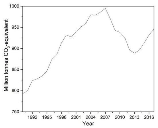
Figure 1. CO2 emissions from the transport sector in Europe (source [18]).
Therefore, if the transport sector wants to be fully CO2 zero-emission, technological innovations used in other sectors must be considered to apply in road freight transport. The carbon capture and storage (CCS) technologies have been widely explored, but only some have the potential to capture the CO2 produced by ICEv used in road freight transport. CCS systems have been primarily used in power plants because they are the predominant source emitter of CO2 [19]. Until 2019, there were 19 large-scale CCS projects in operation, 4 installations are about to start, and 28 others are in various stages of development, with an estimated CO2 capture of 96 Mton per year [20], corresponding to 0.3% of the total CO2 emissions for 2017. In addition, 100 smaller-scale projects are currently ongoing [21].
The existing CCS systems have been adjusted to the nominal operation of power plants, almost always in a stationary mode. Therefore, in the selection of a CCS system for its implementation in an ICE driven vehicle (ship or truck), adaptation to the typical operating characteristics of the transport sector, such as variations of the mass flow and concentration of species in the FG due to acceleration, decelerations, and engine loads, must be considered. Where applicable, the use of CCS technologies in the transport sector should be coupled with a fuel that produces near-zero particle emissions, not to affect the operation of the selected capture method.
In addition, the selection of a CCS system to operate in the transport sector will depend on the end-use of the CO2 captured onboard. The possibility to produce synthetic methane to be subsequently used as fuel in the internal combustion engine (ICE) should be contemplated if a decarbonized and circular economy is pursued. The generation of synthetic methane combining electrolytic H2 from renewable electricity and CO2 captured from an existing source is a promising Power-to-Gas (PTG) technology due to its versatility [22][23][24][25][26][27] and the possibility of being integrated into the current NG supply and distribution system [28]. In addition, as several studies have shown [29][30], the vehicles that operate with this kind of fuel produce less noise and near-zero particulate matter. Integration of CO2 capture in synthetic methane fuelled engines would close the circle and move the ICE vehicle sector towards CO2 emission neutrality, which will counteract the problems noted above [31][32][33]. To sum up, the integration of CCS in the transport sector could be an excellent way to keep the existing ICE in the market under the upcoming near-zero CO2 emissions scenarios with zero presence of fossil fuels.
2. Carbon Capture and Storage
CCS refers to many technologies that capture CO2 at some stage of a combustion process or an industrial process that produces CO2 as waste [34][35][36]. In the first case, the CO2 capture can be carried out after the combustion process (post-combustion, oxy-combustion and chemical looping combustion) or before the combustion process (pre-combustion), as represented in Figure 2 [37]. The higher the partial pressure of CO2 in the gas, the better the efficiency of adsorption or absorption of CO2 [38][39].
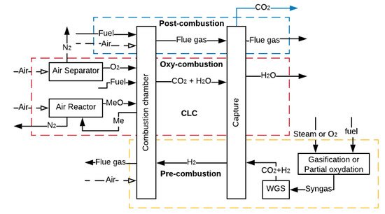
Figure 2. CCS methods (adapted from [37]).
In post-combustion, the capture occurs at a CO2 low partial pressure, while capturing through oxy-combustion, pre-combustion and chemical looping combustion (CLC), whose aim is to increase the CO2 concentration in the flue gas (FG), allows a higher partial pressure of CO2 in the gas. However, to increase the CO2 concentration, it is necessary to use additional equipment such as reactors or air separator units (ASU), which requires a large amount of power, thus decreasing the overall efficiency of the process [40].
In mobile sources as ICE driven ships and vehicles, the CO2 capture could be done by the three CCS methods shown in Figure 2. However, the CO2 capture in post-combustion is the predominant method by the nature of the powertrain used in this sector. According to Wang et al. [41], the main techniques that could be applied for CO2 capture in maritime transport are amine-absorption, temperature swing adsorption (TSA), cryogenisation and membrane processes. On the other hand, according to Sullivan and Sivak [42], the most promising CO2 capture technologies for the freight transport sector are amine-absorption and TSA. A short review of these techniques used in CCS is presented below.
2.1. Amine-Absorption
CO2 capture by amine-absorption is the most mature and economical technology available today used in power plants [43]. According to Joel et al., Salazar et al. and MacDowell et al. [37][44][45], the installation consists of two interconnected columns. In the first column or absorber, the amine absorbs the CO2 from the FG in a counter-current reactor at temperatures between 40 and 60 °C and pressures around 1 bar. The clean FG leaves the absorber from the top, while the solution rich in CO2 is pumped from the bottom to the second column or stripper, where it is heated at temperatures between 80 and 120 °C with steam coming from the reboiler at 2 bars of pressure. This reaction breaks the chains between the CO2 and the amine, and the CO2 is released while the amine remains clean. Then, CO2 is compressed and stored, and the lean solution is repumped to the absorber in a cycling process, as shown in Figure 3 [46][47].
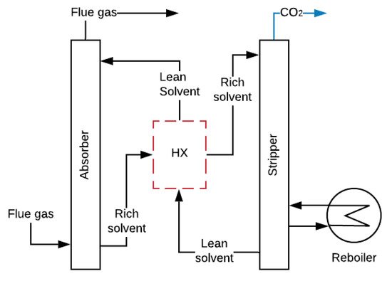
Absorption by amines causes a reduction of approximately 10 points in the overall efficiency of a power plant (there are still no experimental data of mobile sources) [50][51]. This reduction is caused by the vapour extracted in the turbine during the regeneration process and the energy consumed by pumping and compression (parasitic loads), as shown in Figure 3 [52][53]. The required properties of amines to be used in mobiles sources should be low absorption heat, to lessen energy requirements, and high CO2 loading capacity (q), to minimize amine mass in the CO2 capture. Table 1 shows some amines with suitable characteristics for the capture of CO2 in mobile sources.
Table 1. Amine main properties at 300 K, with great potential to be used in mobiles sources.
| Solvent | Rate Constant Reaction [m3/kmol-s] |
Absorption Heat (ΔHabs) [kJ/molCO2] |
Loading Capacity (q) | Amine in the Solution [wt%] | |
|---|---|---|---|---|---|
| [molCO2/molamine] | [molCO2/Lamine] | ||||
| Ethanolamine (MEA) | 8400 [54] | −88.91 [55] | 0.59 [56] | 9.77 | 30 |
| Diethanolamine (DEA) | 1340 [54] | −70.44 [55] | 0.61 [56] | 6.32 | 30 |
| Ammonia (NH3) | 7500 [57] | −65.5 [58] | 0.4 [59][60][61] | 16 | 2.5 |
| Piperazine (Pz) | 53,700 [62] | −80.58 [56] | 0.81 [56][63] | 10.34 | 30 |
| Methyl diethanolamine (MDEA) | 11.15 [64] | −52.51 [56] | 0.74 [65] | 6.51 | 30 |
Main problems with the amine-absorption include the degradation in operation at high temperatures and the need to make the FG free of acid emissions (SO2 and NOx) and particulate matter [66][67]. The amines are chemically unstable and highly corrosive in the presence of oxygen. Due to their high viscosity, aqueous amine solutions at a maximum concentration of 40 wt% [55] are used. One should not forget that amines are toxic to aquatic organisms and react with NOx producing carcinogenic compounds that affect human health [68][69].
2.2. Adsorption
The adsorption process is based on an intermolecular relationship among surface forces in solids and gases, largely dependent on the temperature, partial pressure, surface force and adsorbent pore sizes [46][70]. Several materials have an excellent potential for this process, i.e., Activated Carbon (AC), zeolites, alumina, silica adsorbent, carbon nanotubes, porous polymer networks (PPNs), metal-organic frameworks (MOFs) and others [71][72][73][74]. Furthermore, materials can be improved with the impregnation of amine sorbents [75]. The adsorption process cannot be used if there are high concentrations of CO2 in the FG because of the general low q of the sorbent, as shown in Table 2, but it is adequate for concentrations under 20% [76].
Table 2. Properties of materials used in adsorption.
| Sorbent | Adsorption Heat (ΔHads) [kJ/molCO2] |
Loading Capacity (q) | Selectivity CO2/N2 | Specific Heat (cp) [kJ/kgK] |
* Density (ρ) [kg/m3] |
|
|---|---|---|---|---|---|---|
| [kgCO2/kgadsorbent] | ** [molCO2/Ladsorbent] | |||||
| Polyethylenimine/silica (PEI/HMS) [77] | −95.04 | 0.059 | - | 1.81 | - | |
| PPN-6-CH2-TETA [73][78] | −48.22 | 0.06 | 1.21 | >10,000 | 0.985 | 883.8 |
| PPN-6-CH2-DETA [73][78] | −45.32 | 0.112 | 2.04 | >10,000 | 0.985 | 805 |
| PEI-PS-50 [79] | −70.4 | 0.1276 | - | 1.65 | - | |
| Zeolite (13X) [80][81] | −49.72 | 0.176 | 2.6 | 17.46 | 1.07 | 1430 |
| MOF-74-Mg [73][78] | −37.4 | 0.2284 | 4.75 | 209 | 0.896 | 914.9 |
* Crystallographic density. ** Calculated with a 50 % of the crystallographic density.
One of the techniques with the most significant potential to capture CO2 in ICEv is adsorption. Specifically, the TSA technique is the most suitable process due to the high thermal energy available in the FG in ICEv. TSA is a cyclic process that has four stages, as shown in Figure 4. Initially, the CO2 adsorption occurs at low temperatures (approximately 30 °C). Then, the sorbent bed is heated until the desorption temperature (around 150 °C). Thereafter, at this temperature, the sorbent releases the retained CO2. Finally, the bed is cooled to start another cycle of adsorption [82][83][84][85]. In general, the main limitations of this process are the reduction in the adsorption capacity when the FG stream is wet due to the hydrophilic character of the materials [86] and the low q (Table 2), which necessitates a large amount of material to achieve more quantities of captured CO2. However, the adsorption process can be adapted to several operation conditions because of its flexibility to configure the reactors [86][87][88].
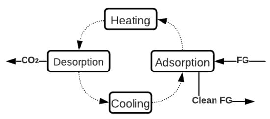
Figure 4. General description of TSA Process (adapted from [82]).
2.3. Carbonate Looping
Carbonate Looping (CL), represented in Figure 5, has been widely investigated for CO2 capture, and CO2 captures up to 90% have been experimentally achieved [89]. The process involves reacting the FG with CaO at 650 °C and atmospheric pressure to obtain calcium carbonate CaCO3 and FG without CO2 [90]. The CaCO3 is carried to a second reactor where it is calcined at temperatures above 900 °C with pure oxygen, fuel and CO2, and regenerate sorbent (CaO) is produced [90][91]. This technology is very advantageous because it can also work for thermal energy storage. The calcination of solid CaCO3 with concentrated solar energy produces CO2 and CaO, which are stored for subsequent use [92]. However, this process requires high levels of energy consumption in the ASU to supply pure O2.
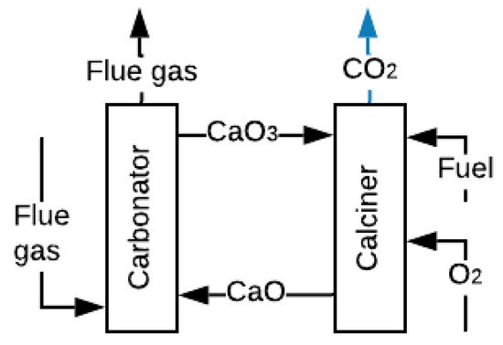
Figure 5. Scheme of the CL process (adapted from [90]).
2.4. Membranes
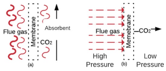
CO2 capture with membranes is a concept developed in the nineteen-eighties and includes benefits such as being a compact, flexible and modular solution, as well as ease of maintenance and operation [93][94]. The involved mechanisms are solution/diffusion, adsorption/diffusion, molecular sieve, and ionic transport [46][95]. Figure 6a shows a gas absorption membrane contactor. In this membrane, the CO2 mass diffuses across the membrane and absorbs into the absorbent [96]. These membranes are usually composed of commercial polymers that absorb the CO2 from the FG. Figure 6b shows the gas separation membranes. In these membranes, the CO2 (in the FG at high pressure) diffuses through the membrane pores faster than other components [46]. Membranes that work under the separation principle are manufactured with ceramics, polymerics, and blends of both materials [46][97].
Several studies have tested the use of advanced materials, such as graphene, as fillers in a polymer matrix for separation [98] or have shown that a cascade configuration for compressors improved the energy consumption by achieving an increase in the efficiency of 3.8% with 70% CO2 separation in real-sized power plants [99]. Mathematical simulations of multi-stage membrane networks for coal-fired power plants [100] have shown that the optimal configuration is a three-stage configuration with a 98% rate of CO2 capture.
As this technology is in its first stage of implementation, the only applications have occurred at a lab-scale, so that the behaviour at a pilot-scale and full scale remains unknown [66]. Ongoing research is attempting to overcome the capture ratio, which cannot attain good values in only one membrane stage if the concentration of CO2 is high. For example, for a typical concentration of a coal power plant of approximately 15%, multiple stages of membranes are required, increasing the operational cost [101][102]. However, compared to the absorption process with MEA-scrubbing, membranes are still not competitive, as they need 2.3 times the cost of the operation, according to Jafari et al. [103]. Therefore, several authors have suggested that reducing the price of the membranes would have a significant impact due to the large area required to deal with typical gas flows [104].
2.5. Other Forms for CCS
There are other methods for CO2 capture that could be excellent alternatives to the previously described methods if the experimental stages are completed. Cryogenic CO2 capture has been able to accomplish a CO2 capture of approximately 99.99% [105]. Song et al. [106] describe seven methods (cryogenic packed bed, external cooling loop cryogenic carbon capture, anti-sublimation, cryogenic distillation, controlled freezing zone, cryoCell process and Stirling cooler system) for processing. The main problem with the cryogenic process is the high energy consumption required to keep the temperatures or to increase the pressures [106], and complications for the CO2 depositions over the heat transfer surface below its triple point (517 kPa and 56.6 °C) [107]. The bio-fixation of CO2 with microalgae for biodiesel production is a method that takes advantage of the high photosynthesis rate of microalgae. The process consists of passing the FG through a microalgae crop in the presence of solar radiation so that the microalgae capture the CO2. Moreover, this process is advantageous because it could be used in parallel with wastewater treatment and thus could result in a double benefit [108].
This entry is adapted from the peer-reviewed paper 10.3390/en14216865
References
- IEA Total Final Consumption (TFC) by Sector, World 1990–2017. Available online: https://www.iea.org/data-and-statistics?country=WORLD&fuel=Energy%20consumption&indicator=Total%20final%20consumption%20(TFC)%20by%20sector (accessed on 27 November 2019).
- Bellocchi, S.; De Falco, M.; Gambini, M.; Manno, M.; Stilo, T.; Vellini, M. Opportunities for power-to-Gas and Power-to-liquid in CO2-reduced energy scenarios: The Italian case. Energy 2019, 175, 847–861.
- Hof, A.F.; den Elzen, M.G.J.; Admiraal, A.; Roelfsema, M.; Gernaat, D.E.H.J.; van Vuuren, D.P. Global and regional abatement costs of Nationally Determined Contributions (NDCs) and of enhanced action to levels well below 2 °C and 1.5 °C. Environ. Sci. Policy 2017, 71, 30–40.
- European Commission. A Clean Planet for all A European Long-Term Strategic Vision for a Prosperous, Modern, Competitive and Climate Neutral Economy; European Commission: Luxembourg, 2018; Volume 773, p. 114.
- Tamborra, M. European Commission, DG Research. 2006. Available online: https://www.iccr.org/ (accessed on 27 November 2019).
- Akram, M.; Ali, U.; Best, T.; Blakey, S.; Finney, K.N.; Pourkashanian, M. Performance evaluation of PACT Pilot-plant for CO2 capture from gas turbines with Exhaust Gas Recycle. Int. J. Greenh. Gas Control. 2016, 47, 137–150.
- Leach, F.; Kalghatgi, G.; Stone, R.; Miles, P. The scope for improving the efficiency and environmental impact of internal combustion engines. Transp. Eng. 2020, 1, 100005.
- Huang, Y.; Ng, E.C.Y.; Zhou, J.L.; Surawski, N.C.; Chan, E.F.C.; Hong, G. Eco-driving technology for sustainable road transport: A review. Renew. Sustain. Energy Rev. 2018, 93, 596–609.
- Fafoutellis, P.; Mantouka, E.G.; Vlahogianni, E.I. Eco-driving and its impacts on fuel efficiency: An overview of technologies and data-driven methods. Sustainability 2021, 13, 226.
- Agudelo, A.F.; García-Contreras, R.; Agudelo, J.R.; Armas, O. Potential for exhaust gas energy recovery in a diesel passenger car under European driving cycle. Appl. Energy 2016, 174, 201–212.
- Merkisz, J.; Fuc, P.; Lijewski, P.; Ziolkowski, A.; Wojciechowski, K.T. The Analysis of Exhaust Gas Thermal Energy Recovery Through a TEG Generator in City Traffic Conditions Reproduced on a Dynamic Engine Test Bed. J. Electron. Mater. 2015, 44, 1704–1715.
- Arsie, I.; Cricchio, A.; Pianese, C.; Ricciardi, V.; De Cesare, M. Modeling analysis of waste heat recovery via thermo-electric generator and electric turbo-compound for CO2 reduction in automotive SI engines. Energy Procedia 2015, 82, 81–88.
- Sprouse, C.; Depcik, C. Review of organic Rankine cycles for internal combustion engine exhaust waste heat recovery. Appl. Therm. Eng. 2013, 51, 711–722.
- Kühlwein, J. Driving Resistances of Light-Duty Vehicles in Europe: Present Situation, Trends and Scenarios for 2025. Communications 2016, 49, 847129-102.
- European Commission. Roadmap to a Single European Transport Area—Towards a Competitive and Resource Efficient Transport System; European Commission: Brussels, Belgium, 2011.
- EV-Volumes—The Electric Vehicle World Sales Database. Available online: https://www.ev-volumes.com/news/global-bev-phev-sales-for-2019/%0Ahttp://www.ev-volumes.com/country/total-euefta-plug-in-vehicle-volumes-2/ (accessed on 29 November 2019).
- Amarakoon, S.; Smith, J.; Segal, B. Lithium-ion Batteries and Nanotechnology for Electric Vehicles; EPA 744-R-12-001; US Environmental Protection Agency: Wasinghton, DC, USA, 2012.
- European Environmental Agency. Greenhouse Gas Emissions from Transport in Europe—European Environment Agency; European Environmental Agency: København, Denmark, 2018; pp. 1–7.
- Wang, D.; Li, S.; Liu, F.; Gao, L.; Sui, J. Post combustion CO2 capture in power plant using low temperature steam upgraded by double absorption heat transformer. Appl. Energy 2018, 227, 603–612.
- New Wave of CCS Activity: Ten Large-Scale Projects Announced—Global CCS Institute. Available online: https://www.globalccsinstitute.com/news-media/press-room/media-releases/new-wave-of-ccs-activity-ten-large-scale-projects-announced/ (accessed on 17 February 2020).
- International Energy Agency. 20 Years Carbon Capture Storage; OECD: Paris, France, 2016.
- Eveloy, V.; Gebreegziabher, T. A Review of Projected Power-to-Gas Deployment Scenarios. Energies 2018, 11, 1824.
- Llera, E.; Romeo, L.M.; Bailera, M.; Osorio, J.L. Exploring the integration of the power to gas technologies and the sustainable transport. Int. J. Energy Prod. Manag. 2018, 3, 1–9.
- Streibel, M.; Nakaten, N.; Kempka, T.; Kühn, M. Analysis of an integrated carbon cycle for storage of renewables. Energy Procedia 2013, 40, 202–211.
- Kühn, M.; Nakaten, N.; Streibel, M.; Kempka, T. CO2 geological storage and utilization for a carbon neutral “power-to-gas-to-power” cycle to even out fluctuations of renewable energy provision. Energy Procedia 2014, 63, 8044–8049.
- Götz, M.; Lefebvre, J.; Mörs, F.; McDaniel Koch, A.; Graf, F.; Bajohr, S.; Reimert, R.; Kolb, T. Renewable Power-to-Gas: A technological and economic review. Renew. Energy 2016, 85, 1371–1390.
- Rönsch, S.; Schneider, J.; Matthischke, S.; Schlüter, M.; Götz, M.; Lefebvre, J.; Prabhakaran, P.; Bajohr, S. Review on methanation—From fundamentals to current projects. Fuel 2016, 166, 276–296.
- Hagos, D.A.; Ahlgren, E. A State-of-the Art Review on the Development of CNG/LNG Infrastructure and Natural Gas Vehicles (NGVs); Chalmers University of Technology: Göteborg, Sweden, 2017.
- Osorio-Tejada, J.L.; Llera-Sastresa, E.; Scarpellini, S. A multi-criteria sustainability assessment for biodiesel and liquefied natural gas as alternative fuels in transport systems. J. Nat. Gas Sci. Eng. 2017, 42, 169–186.
- Osorio-Tejada, J.L.; Llera-Sastresa, E.; Scarpellini, S. Liquefied natural gas: Could it be a reliable option for road freight transport in the EU? Renew. Sustain. Energy Rev. 2017, 71, 785–795.
- Kalghatgi, G.; Levinsky, H.; Colket, M. Future transportation fuels. Prog. Energy Combust. Sci. 2018, 69, 103–105.
- Horvath, S.; Fasihi, M.; Breyer, C. Techno-economic analysis of a decarbonized shipping sector: Technology suggestions for a fleet in 2030 and 2040. Energy Convers. Manag. 2018, 164, 230–241.
- Mikulčić, H.; Ridjan Skov, I.; Dominković, D.F.; Wan Alwi, S.R.; Manan, Z.A.; Tan, R.; Duić, N.; Hidayah Mohamad, S.N.; Wang, X. Flexible Carbon Capture and Utilization technologies in future energy systems and the utilization pathways of captured CO2. Renew. Sustain. Energy Rev. 2019, 114, 109338.
- Boot-Handford, M.E.; Abanades, J.C.; Anthony, E.J.; Blunt, M.J.; Brandani, S.; Mac Dowell, N.; Fernández, J.R.; Ferrari, M.C.; Gross, R.; Hallett, J.P.; et al. Carbon capture and storage update. Energy Environ. Sci. 2014, 7, 130–189.
- Belaissaoui, B.; Le Moullec, Y.; Willson, D.; Favre, E. Hybrid membrane cryogenic process for post-combustion CO2 capture. J. Memb. Sci. 2012, 415–416, 424–434.
- Voldsund, M.; Gardarsdottir, S.O.; De Lena, E.; Pérez-Calvo, J.F.; Jamali, A.; Berstad, D.; Fu, C.; Romano, M.; Roussanaly, S.; Anantharaman, R.; et al. Comparison of technologies for CO2 capture from cement production—Part 1: Technical evaluation. Energies 2019, 12, 559.
- MacDowell, N.; Florin, N.; Buchard, A.; Hallett, J.; Galindo, A.; Jackson, G.; Adjiman, C.S.; Williams, C.K.; Shah, N.; Fennell, P. An overview of CO2 capture technologies. Energy Environ. Sci. 2010, 3, 1645–1669.
- Sipöcz, N.; Hernandez-Nogales, A.; Gonzalez-Salazar, M.A.; Shisler, R.; Lissianski, V. Low temperature CO2 capture for near-term applications. Energy Procedia 2013, 37, 1228–1238.
- Hu, Y.; Yan, J. Characterization of flue gas in oxy-coal combustion processes for CO2 capture. Appl. Energy 2012, 90, 113–121.
- Olajire, A.A. CO2 capture and separation technologies for end-of-pipe applications—A review. Energy 2010, 35, 2610–2628.
- Wang, H.; Zhou, P.; Wang, Z. Reviews on current carbon emission reduction technologies and projects and their feasibilities on ships. J. Mar. Sci. Appl. 2017, 16, 129–136.
- Sullivan, J.M.; Sivak, M. Carbon Capture in Vehicles: A Review of General Support, Available Mechanisms, and Consumer Acceptance Issues; University of Michigan, Ann Arbor, Transportation Research Institute: Ann Arbor, MI, USA, 2012.
- Echevarria Huaman, R.N. A Review on: CO2 Capture Technology on Fossil Fuel Power Plant. J. Fundam. Renew. Energy Appl. 2015, 5.
- Joel, A.S.; Wang, M.; Ramshaw, C. Modelling and simulation of intensified absorber for post-combustion CO2 capture using different mass transfer correlations. Appl. Therm. Eng. 2015, 74, 47–53.
- Salazar, J.; Diwekar, U.; Joback, K.; Berger, A.H.; Bhown, A.S. Solvent selection for post-combustion CO2 capture. Energy Procedia 2013, 37, 257–264.
- Mondal, M.K.; Balsora, H.K.; Varshney, P. Progress and trends in CO2 capture/separation technologies: A review. Energy 2012, 46, 431–441.
- Jonshagen, K.; Sipöcz, N.; Genrup, M. A Novel Approach of Retrofitting a Combined Cycle with Post Combustion CO2 Capture. J. Eng. Gas Turbines Power 2011, 133, 1–7.
- Xue, B.; Yu, Y.; Chen, J.; Luo, X.; Wang, M. A comparative study of MEA and DEA for post-combustion CO2 capture with different process configurations. Int. J. Coal Sci. Technol. 2017, 4, 15–24.
- Zhai, R.; Liu, H.; Wu, H.; Yu, H.; Yang, Y. Analysis of integration of MEA-based CO2 capture and solar energy system for coal-based power plants based on thermo-economic structural theory. Energies 2018, 11, 1284.
- Goto, K.; Yogo, K.; Higashii, T. A review of efficiency penalty in a coal-fired power plant with post-combustion CO2 capture. Appl. Energy 2013, 111, 710–720.
- Eldardiry, H.; Habib, E. Carbon capture and sequestration in power generation: Review of impacts and opportunities for water sustainability. Energy. Sustain. Soc. 2018, 8, 6.
- Hanak, D.P.; Biliyok, C.; Manovic, V. Efficiency improvements for the coal-fired power plant retrofit with CO2 capture plant using chilled ammonia process. Appl. Energy 2015, 151, 258–272.
- Borhani, T.N.; Wang, M. Role of solvents in CO2 capture processes: The review of selection and design methods. Renew. Sustain. Energy Rev. 2019, 114, 109299.
- Sada, E.; Kumazawa, H.; Butt, M.A. Gas absorption with consecutive chemical reaction: Absorption of carbon dioxide into aqueous amine solutions. Can. J. Chem. Eng. 1976, 54, 421–424.
- Kim, Y.E.; Lim, J.A.; Jeong, S.K.; Yoon, Y.I.; Bae, S.T.; Nam, S.C. Comparison of carbon dioxide absorption in aqueous MEA, DEA, TEA, and AMP solutions. Bull. Korean Chem. Soc. 2013, 34, 783–787.
- El Hadri, N.; Quang, D.V.; Goetheer, E.L.V.; Abu Zahra, M.R.M. Aqueous amine solution characterization for post-combustion CO2 capture process. Appl. Energy 2017, 185, 1433–1449.
- Derks, P.W.J.; Versteeg, G.F. Kinetics of absorption of carbon dioxide in aqueous ammonia solutions. Energy Procedia 2009, 1, 1139–1146.
- Qin, F.; Wang, S.; Kim, I.; Svendsen, H.F.; Chen, C. Heat of absorption of CO2 in aqueous ammonia and ammonium carbonate/carbamate solutions. Int. J. Greenh. Gas Control. 2011, 5, 405–412.
- Qi, G.; Wang, S.; Yu, H.; Wardhaugh, L.; Feron, P.; Chen, C. Development of a rate-based model for CO2 absorption using aqueous NH3 in a packed column. Int. J. Greenh. Gas Control. 2013, 17, 450–461.
- Yang, N.; Yu, H.; Li, L.; Xu, D.; Han, W.; Feron, P. Aqueous Ammonia (NH3) Based Post Combustion CO2 Capture: A Review. Oil Gas Sci. Technol. 2014, 69, 931–945.
- Yu, H.; Morgan, S.; Allport, A.; Cottrell, A.; Do, T.; Wardhaugh, J.M.G.L.; Feron, P. Results from trialling aqueous NH3 based post combustion capture in a pilot plant at Munmorah power station: Desorption. Chem. Eng. Res. Des. 2012, 89, 753–758.
- Bishnoi, S.; Rochelle, G.T. Absorption of carbon dioxide into aqueous piperazine: Reaction kinetics, mass transfer and solubility. Chem. Eng. Sci. 2000, 55, 5531–5543.
- Chen, X.; Rochelle, G.T. Aqueous piperazine derivatives for CO2 capture: Accurate screening by a wetted wall column. Chem. Eng. Res. Des. 2011, 89, 1693–1710.
- Singto, S.; Supap, T.; Idem, R.; Tontiwachwuthikul, P.; Tantayanon, S. The Effect of Chemical Structure of Newly Synthesized Tertiary Amines Used for the Post Combustion Capture Process on Carbon dioxide (CO2): Kinetics of CO2 Absorption Using the Stopped-Flow Apparatus and Regeneration, and Heat Input of CO2 Regeneration. Energy Procedia 2017, 114, 852–859.
- Ali, B.S.; Aroua, M.K. Effect of piperazine on CO2 loading in aqueous solutions of MDEA at low pressure. Int. J. Thermophys. 2004, 25, 1863–1870.
- Wang, Y.; Zhao, L.; Otto, A.; Robinius, M.; Stolten, D. A Review of Post-combustion CO2 Capture Technologies from Coal-fired Power Plants. Energy Procedia 2017, 114, 650–665.
- Conway, W.; Yang, Q.; James, S.; Wei, C.C.; Bown, M.; Feron, P.; Puxty, G. Designer amines for post combustion CO2 capture processes. Energy Procedia 2014, 63, 1827–1834.
- Thompson, J.; Matin, N.; Liu, K. Solubility and Thermodynamic Modeling of Carcinogenic Nitrosamines in Aqueous Amine Solvents for CO2 Capture. Energy Procedia 2017, 114, 1038–1044.
- Kimura, H.; Kubo, T.; Shimada, M.; Kitamura, H.; Fujita, K.; Suzuki, K.; Yamamoto, K.; Akai, M. Environmental Risk Assessment of MEA and its Degradation Products from Post-combustion CO2 Capture Pilot Plant: Drafting Technical Guidelines. Energy Procedia 2017, 114, 6490–6500.
- Kumar, S.; Srivastava, R.; Koh, J. Utilization of zeolites as CO2 capturing agents: Advances and future perspectives. J. CO2 Util. 2020, 41, 101251.
- Lu, C.; Bai, H.; Wu, B.; Su, F.; Hwang, J.F. Comparative study of CO2 capture by carbon nanotubes, activated carbons, and zeolites. Energy Fuels 2008, 22, 3050–3056.
- Hinkov, I.; Lamari, F.D.; Langlois, P.; Dicko, M.; Chilev, C.; Pentchev, I. Carbon dioxide capture by adsorption (review). J. Chem. Technol. Metall. 2016, 51, 609–626.
- Verdegaal, W.M.; Wang, K.; Sculley, J.P.; Wriedt, M.; Zhou, H.C. Evaluation of Metal-Organic Frameworks and Porous Polymer Networks for CO2-Capture Applications. ChemSusChem 2016, 9, 636–643.
- Yu, P.; Luo, Z.; Wang, Q.; Fang, M.; Zhou, J.; Wang, W.; Liang, X.; Cai, W. Activated carbon-based CO2 uptake evaluation at different temperatures: The correlation analysis and coupling effects of the preparation conditions. J. CO2 Util. 2020, 40, 101214.
- Veneman, R.; Kamphuis, H.; Brilman, D.W.F. Post-combustion CO2 capture using supported amine sorbents: A process integration study. Energy Procedia 2013, 37, 2100–2108.
- Hasan, M.M.F.; Baliban, R.C.; Elia, J.A.; Floudas, C.A. Modeling, simulation, and optimization of postcombustion CO2 capture for variable feed concentration and flow rate. 2. Pressure swing adsorption and vacuum swing adsorption processes. Ind. Eng. Chem. Res. 2012, 51, 15665–15682.
- Zhang, W.; Liu, H.; Sun, Y.; Cakstins, J.; Sun, C.; Snape, C.E. Parametric study on the regeneration heat requirement of an amine-based solid adsorbent process for post-combustion carbon capture. Appl. Energy 2016, 168, 394–405.
- Huck, J.M.; Lin, L.C.; Berger, A.H.; Shahrak, M.N.; Martin, R.L.; Bhown, A.S.; Haranczyk, M.; Reuter, K.; Smit, B. Supporting Information: Evaluating different classes of porous materials for carbon capture. Energy Environ. Sci. 2014, 7, 4132–4146.
- Quang, D.V.; El Hadri, N.; Abu-zahra, M.R.M. Reduction in the regeneration energy of CO2 capture process by impregnating amine solvent onto precipitated silica. Eur. Sci. J. 2013, 9, 82–102.
- Won, W.; Lee, S.; Lee, K.S. Modeling and parameter estimation for a fixed-bed adsorption process for CO2 capture using zeolite 13X. Sep. Purif. Technol. 2012, 85, 120–129.
- Al Mousa, A.; Abouelnasr, D.; Loughlin, K.F. Saturation loadings on 13X (faujasite) zeolite above and below the critical conditions. Part II: Unsaturated and cyclic hydrocarbons data evaluation and modeling. Adsorption 2015, 21, 321–332.
- Hedin, N.; Andersson, L.; Bergström, L.; Yan, J. Adsorbents for the post-combustion capture of CO2 using rapid temperature swing or vacuum swing adsorption. Appl. Energy 2013, 104, 418–433.
- Creamer, A.E.; Gao, B. Carbon-based adsorbents for postcombustion CO2 capture: A critical review. Environ. Sci. Technol. 2016, 50, 7276–7289.
- Raganati, F.; Chirone, R.; Ammendola, P. CO2 Capture by Temperature Swing Adsorption: Working Capacity as Affected by Temperature and CO2 Partial Pressure. Ind. Eng. Chem. Res. 2020, 59, 3593–3605.
- Song, C.; Kansha, Y.; Fu, Q.; Ishizuka, M.; Tsutsumi, A. Reducing energy consumption of advanced PTSA CO2 capture process-Experimental and numerical study. J. Taiwan Inst. Chem. Eng. 2016, 64, 69–78.
- Zanco, S.E.; Joss, L.; Hefti, M.; Gazzani, M.; Mazzotti, M. Addressing the Criticalities for the Deployment of Adsorption-based CO2 Capture Processes. Energy Procedia 2017, 114, 2497–2505.
- Marx, D.; Joss, L.; Hefti, M.; Mazzotti, M. Temperature Swing Adsorption for Postcombustion CO2 Capture: Single- and Multicolumn Experiments and Simulations. Ind. Eng. Chem. Res. 2016, 55, 1401–1412.
- Dhoke, C.; Zaabout, A.; Cloete, S.; Amini, S. Review on Reactor Configurations for Adsorption-Based CO2 Capture. Ind. Eng. Chem. Res. 2021, 60, 3779–3798.
- Ströhle, J.; Junk, M.; Kremer, J.; Galloy, A.; Epple, B. Carbonate looping experiments in a 1 MWth pilot plant and model validation. Fuel 2014, 127, 13–22.
- Perejón, A.; Romeo, L.M.; Lara, Y.; Lisbona, P.; Martínez, A.; Valverde, J.M. The Calcium-Looping technology for CO2 capture: On the important roles of energy integration and sorbent behavior. Appl. Energy 2016, 162, 787–807.
- Alonso, M.; Rodríguez, N.; González, B.; Grasa, G.; Murillo, R.; Abanades, J.C. Carbon dioxide capture from combustion flue gases with a calcium oxide chemical loop. Experimental results and process development. Int. J. Greenh. Gas Control. 2010, 4, 167–173.
- Ortiz, C.; Romano, M.C.; Valverde, J.M.; Binotti, M.; Chacartegui, R. Process integration of Calcium-Looping thermochemical energy storage system in concentrating solar power plants. Energy 2018, 155, 535–551.
- Ahmad, J.; Rehman, W.U.; Deshmukh, K.; Basha, S.K.; Ahamed, B.; Chidambaram, K. Recent Advances in Poly (Amide-B-Ethylene) Based Membranes for Carbon Dioxide (CO2) Capture: A Review. Polym. Technol. Mater. 2019, 58, 366–383.
- Turi, D.M.; Ho, M.; Ferrari, M.C.; Chiesa, P.; Wiley, D.E.; Romano, M.C. CO2 capture from natural gas combined cycles by CO2 selective membranes. Int. J. Greenh. Gas Control. 2017, 61, 168–183.
- Sifat, N.S.; Haseli, Y. A critical review of CO2 capture technologies and prospects for clean power generation. Energies 2019, 12, 4143.
- Khaisri, S.; deMontigny, D.; Tontiwachwuthikul, P.; Jiraratananon, R. Comparing membrane resistance and absorption performance of three different membranes in a gas absorption membrane contactor. Sep. Purif. Technol. 2009, 65, 290–297.
- Norahim, N.; Yaisanga, P.; Faungnawakij, K.; Charinpanitkul, T.; Klaysom, C. Recent Membrane Developments for CO2 Separation and Capture. Chem. Eng. Technol. 2018, 41, 211–223.
- Fernández-Barquín, A.; Casado-Coterillo, C.; Etxeberria-Benavides, M.; Zuñiga, J.; Irabien, A. Comparison of Flat and Hollow-Fiber Mixed-Matrix Composite Membranes for CO2 Separation with Temperature. Chem. Eng. Technol. 2017, 40, 997–1007.
- Franz, J.; Schiebahn, S.; Zhao, L.; Riensche, E.; Scherer, V.; Stolten, D. Investigating the influence of sweep gas on CO2/N2 membranes for post-combustion capture. Int. J. Greenh. Gas Control. 2013, 13, 180–190.
- Arias, A.M.; Mussati, M.C.; Mores, P.L.; Scenna, N.J.; Caballero, J.A.; Mussati, S.F. Optimization of multi-stage membrane systems for CO2 capture from flue gas. Int. J. Greenh. Gas Control. 2016, 53, 371–390.
- Favre, E. Carbon dioxide recovery from post-combustion processes: Can gas permeation membranes compete with absorption? J. Memb. Sci. 2007, 294, 50–59.
- Zhao, L.; Riensche, E.; Blum, L.; Stolten, D. Multi-stage gas separation membrane processes used in post-combustion capture: Energetic and economic analyses. J. Memb. Sci. 2010, 359, 160–172.
- Jafari, M.; Ghasemzadeh, K.; Amiri, T.Y.; Basile, A. Comparative Study of Membrane and Absorption Processes Performance and their Economic Evaluation for CO2 Capturing from Flue Gas. Gas Process. J. 2019, 7, 37–52.
- Zhao, L.; Weber, M.; Stolten, D. Comparative investigation of polymer membranes for post-combustion capture. Energy Procedia 2013, 37, 1125–1134.
- Yousef, A.M.; El-Maghlany, W.M.; Eldrainy, Y.A.; Attia, A. New approach for biogas purification using cryogenic separation and distillation process for CO2 capture. Energy 2018, 156, 328–351.
- Song, C.; Liu, Q.; Deng, S.; Li, H.; Kitamura, Y. Cryogenic-based CO2 capture technologies: State-of-the-art developments and current challenges. Renew. Sustain. Energy Rev. 2019, 101, 265–278.
- Berger, A.H.; Hoeger, C.; Baxter, L.; Bhown, A.S. Evaluation of Cryogenic Systems for Post Combustion CO2 Capture. In Proceedings of the 14th Greenhouse Gas Control Technologies Conference, Melbourne, Australia, 21–26 October 2018; pp. 1–8.
- Razzak, S.A.; Ali, S.A.M.; Hossain, M.M.; deLasa, H. Biological CO2 fixation with production of microalgae in wastewater—A review. Renew. Sustain. Energy Rev. 2017, 76, 379–390.
This entry is offline, you can click here to edit this entry!