CFD (Computational Fluid Dynamics) is one of the computer simulation methods used to characterize fluid flow behavior under certain geometries with boundary conditions. The criterion for its performance is how well numerical simulation outcomes align with experimental results conducted under specific conditions, and how well simulations can predict extremely complicated processes that cannot be analyzed in the real world. CFD has gained recognition as an emerging science around the world, particularly since the late 2000s when there was a significant increase in the development and application of CFD to all areas related to fluid behaviors associated with momentum, heat, and mass transfer.
- food 3D printing
- computational fluid dynamics (CFD)
- Residual stress
- Die swell
1. Introduction
Three-dimensional printing (3DP) is a rapid prototyping technology that combines material science with computing and control technologies [1]. The application of 3DP to food began primarily with digitally controlled extrusion operations that could accurately build up the material deposition layer by layer from a pre-designed file such as stereolithography (STL) or computer-aided design (CAD) [2,3]. Several studies have emerged with strong efforts in applying 3DP technology to various designs of food products. In the early stage, the material used in food 3DP was limited to chocolate products [4,5,6], but recently, various materials have been applied successfully and their characteristics in the 3DP have been reported (i.e., potato starch with pea protein, wheat, corn starch, lemon juice gel, alginate with pea protein, cereal food, oat protein, meat product, and surimi [7,8,9,10,11]). 3DP applications were accompanied by a large number of trial-and-error attempts and conservative designs, which resulted in a waste of resources and time during the experiments. This is in part due to a lack of accurate instruments for predicting the results of the process [9]. Recently, patents associated with food 3DP technology have presented computational methods, mainly computational fluid dynamic (CFD) simulation, to predict and quantify the performance of 3DP [12,13,14].
CFD is one of the computer simulation methods used to characterize fluid flow behavior under certain geometries with boundary conditions [12,14]. The criterion for its performance is how well numerical simulation outcomes align with experimental results conducted under specific conditions, and how well simulations can predict extremely complicated processes that cannot be analyzed in the real world [9]. CFD has gained recognition as an emerging science around the world, particularly since the late 2000s when there was a significant increase in the development and application of CFD to all areas related to fluid behaviors associated with momentum, heat, and mass transfer [15]. As a result of its ability to anticipate the success of modern designs or systems before they are manufactured or applied, CFD has played an important role in many industries in the engineering design and research environments [16]. CFD is being used increasingly in the food and bioprocess industries by researchers, system manufacturers, and process engineers to study the flow behavior and efficiency of process equipment such as baking ovens, refrigerators, spray dryers, and 3D printers [9,17,18]. In the 3DP process, CFD technology has been used to identify the critical parameters that dictate the shape of the printed product as well as to find the best material deposition strategy. Thus, CFD has contributed to the reduction in production costs, improvements in the product quality, and increase in productivity (i.e., printing speed) [12,19,20].
In the design of 3DP food products and 3DP processes, the CFD simulations are now considered to be standard numerical tools to predict not only the fluid behavior during extrusion, but also the complicated flow characteristics associated with heat and mass transfer, phase transfer (i.e., solidification), chemical reactions (i.e., bindings and wall stickiness), mechanical movements (i.e., impeller turning, or pistons movement), and stress or deformation of related solid structures (i.e., total collapse) [9,21]. The CFD model involved in 3DP has been continuously developed and extensively studied. Woodfield et al. [22] defined the flow behavior of biomaterials through the nozzle using the Hagen–Poiseuille rule. Based on the rheological properties of the material and layer thickness, Oyinloye and Yoon [9] evaluated the influence of residual-stress components and total deformation across the printed alginate and pea protein sample. Li et al. [23] developed a numerical model for the relationship between volumetric velocity in gels, scaffold pore diameter, and porosity. The fluid flow properties of lemon juice gel in the syringe were also studied using CFD [1].
Many review articles have examined the general applications of CFD for various unit operations involved in food processing for final product such as freezing systems in meat as well as for food ingredients such as spray drying of tomato pulp [15,17,24,25,26,27]. To the best of our knowledge, previous reviews have focused mainly on the material properties, food formulations, and machine design for 3D printing; however, one research paper focused on the use of CFD in terms of tissue engineering with potential in 3DP fabrication [11]. Unlike previous studies, this paper provides an overview of recent developments in CFD use in 3D food printing as well as a discussion of various problems faced during the 3D printing process and their solutions. This work can be seen as a quick guide for the use of CFD in the design of different forms of food 3DP processes.
2. Overview of Studies on the CFD Analysis of 3DP
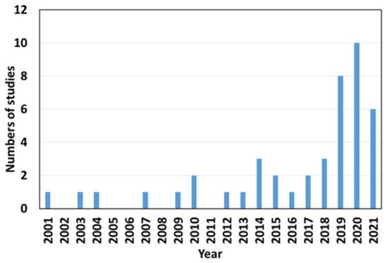
Over the last 20 years, a total of 44 research articles on CFD research and its applications in 3D food printing and extrusion analysis have been reported when searched using specific keywords (CFD, food, numerical simulation, 3D printing, and extrusion process) on Google Scholar. The annual distribution of findings reflects the growing importance of the topic, with more than half of the publications occurring in the last four years ( Figure 1 ). The majority of them focused on the development of novel food items. Several researchers have recently begun exploring issues related to 3D food printing processes such as the die swell effect at the 3D printer nozzle, residual stress component in the extruded products, and the shape of printed products during and after the 3DP process. However, such information is disseminated in several publications with differing technical foci. The related articles published during the last 10 years were analyzed ( Table 1 ).
3. Fundamentals of the CFD Extrusion Process
By applying these conservation laws over discrete spatial volumes in a fluid domain, it is possible to achieve a systematic account of the changes in mass, momentum, and energy as the flow crosses volume boundaries. Although direct solving of Navier–Stokes equations is possible for laminar flow, computationally solving fluid motion in the Kolmogorov microscales in turbulent flow is not yet possible; hence, turbulence models need to be solved in addition to the Navier–Stokes equations in the case of turbulent flow regime, which is generally encountered in the modeling of a low viscosity food process because of the high flow rates and complex geometry involved [37]. As a result, choosing a suitable turbulence model is crucial and has a direct impact on the CFD results of the 3DP process. Several review studies are available on selecting the suitable turbulence models for various food processing, comparable to the 3D printing process, based on accuracy, computing time, and cost, thus this review will not go into detail [25,37].
For boundary conditions used in simulations, the various temperature loading conditions such as uniform, time-dependent, or spatially varying temperature throughout the selected geometry are used as boundary conditions to calculate the heat losses due to conduction and convection heat transfer associated with the 3DP process. The heat source for 3DP on a localized distribution spot is usually assumed to be an ellipsoid-moving heat source with a normally distributed heat flux density in the form of a Gaussian function ( Figure 2 ). The localized heat distribution strongly affects the 3DP process as well as the 3DP products. Thus, temperature-dependent heat losses around the geometry must be analyzed. Radiation and convection heat transfer are the major modes for the localized heat distribution for all boundaries in the geometry. In this case, the heat transfer can be modeled by Equation (6), (6) − λ ∂ T ∂ n = α k T − T 0+ ε C 0T 4− T 04 where α k is the heat transfer coefficient due to free convection; ε is the emission coefficient; C 0 is the radiation coefficient; T is the component temperature; and T 0 is the ambient temperature. Radiation and convection are significant only on the upper part of the geometry, but relatively less on the lower part. Thus, ε can be assumed to be 0. The local heating of the component causes an uneven thermal expansion, whereby the colder environment hinders the expansion of the warm areas. This leads to the component-stress formation in the material, which results in deformation [9].
The selection of appropriate approaches to discretize the modeled fluid continuum is a critical factor for the application of CFD. The most prominent of these include finite difference (FD), finite elements (FE), and finite volumes (FV). Due to difficulties in the handling of complex geometry, FD techniques are of limited use in engineering flows. FE has been used to successfully model the piston-based 3DP of the mixture of alginate and pea protein [9] as well as the screw-based 3D extrusion process of potato paste [21]. However, the FE requires special care to ensure a conservative solution. Although the FE method must be carefully formulated to be conservative, it is far more stable than the FD method [40]. The FE method may demand more memory and may require more time to obtain solutions than the FV method [34]. Because of the complexities inherent in programming and implementing this technique, there are few commercial FE software available. Fortunately, such challenges may be avoided by employing FV approaches [41] that provide ease in understanding, programming, memory usage, solution speed, and versatility of finite volumes, particularly for large problems, high Reynolds number turbulent flows, and source term dominated flows. It is now the most commonly used numerical technique in CFD code development, and as a result, it is considered the most commonly used method to form design solutions for the 3DP process. In the FV method, the governing partial differential equations such as the Navier–Stokes equations, the mass and energy conservation equations, and the turbulence equations are developed in a conservative form, and then solved over discrete control volumes.
All CFD problems are defined by initial and boundary conditions, which must be specified correctly. The initial values of heat and mass flow variables must be specified at all solution points in the computational domain. When modeling heat and mass transfer in the 3DP model, the distribution of all flow variables at the inlet boundary must be specified. In the case of 3DP with molten chocolate, the flow variables include inlet volume flow rate, pressure, turbulent intensity, and temperature [47]. The 3D printer’s piston speed along with the dimensional parameters of the 3D printer chamber is used to define the inlet volume flow rate. Temperature and flow property distributions at the inlet are usually specified based on the experimental data [9]. Outlet boundary conditions can be stated and used in conjunction with the inlet boundary conditions. This type of boundary condition is specified mostly where outlet velocity is known. At the outlet of the flow domain, the force conditions are set (Equation (7)); (7) F n = V s = 0 N where subscript n and s represent the normal and tangential components of the force and velocity, respectively. When the 3D printer’s outlet position is far away from the chamber, the flow reaches a fully developed state with no change in the flow direction. As long as a fully developed state is maintained, the gradient of all variables could be equated to zero in the flow direction, except pressure [41]. In the chamber of the 3D printer, the continuity and the momentum conservation equations (Equations (8) and (9)) are usually used: ( 8) ∇ · v ¯ = 0 (9) ρ ∂ ν ∂ t + ν - · ∇ ν = − ∇ p + ∇ · τ = where ν - is the velocity vector; ρ is the material density; p is the hydrostatic pressure; and τ = is the extra stress tensor. Mostly, the effect of gravity is neglected [10,21,28]. This seems to be a reasonable assumption in materials with high viscosity. At the wall boundary condition, models are usually established as no-slip between the material and the wall of the channel during the extrusion process wherein the normal component of velocity is fixed at zero, and the tangential component is set equal to the velocity of the wall (Equation (10)) [1]: (10) V s = V n = 0 mm / s where V s and V n represent tangential and normal components, respectively. Although it may seem counterintuitive, the no-slip condition has been firmly established in both experiment and theory [48]. The wall is the most common boundary condition considered when solving heat and mass flow problems, specifically during the structural analysis of 3D printed food components. The bottom face of the printing bedplate on which molten materials are printed is supplied with a steady pre-heat temperature. Conduction heat transfer between the molten material and the bedplate occurs, and the temperature difference is important to control the cooling rate of the bottom layer. For the boundary conditions involving heat transfer, it is necessary to specify the rate of heat transfer through the walls. In general, the heat flux q ˙ is defined by (Equation (11)): (11) q ˙ = K T b e d − T s a m p l e r s → o r q ˙ = c o n s t a n t where T b e d and T s a m p l e are the bedplate temperature and molten sample temperature, respectively. The overall heat transfer coefficient K depends on the thermal conductivity and thickness of the conductive solid material as well as the fluid material properties (density, heat capacity, etc.) and flow characteristics (geometry specification, turbulence, etc.). The radiant heat coefficient r s is determined by factors specific to the printing environment or the ambient temperature.
4. CFD Applications in Food 3DP
The thermo-mechanical characteristics of food materials are studied in the food 3DP process to predict material behavior during or after printing in a wide range of factors describing their internal states (i.e., temperature, residual stress, and deformations) and structures (i.e., model shape or permeability). Changes in state parameters and structural characteristics of printed food material are induced by the energy exchange and mechanical interaction of a material with the environment. When a material is deformed, the strength describes the critical stresses. The residual stress is usually taken into account throughout the 3D printing process [9].
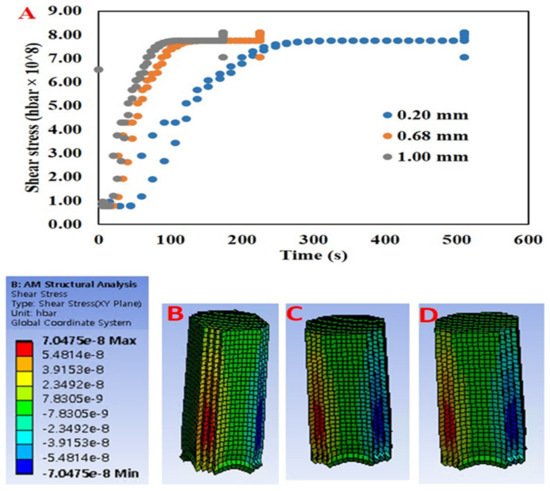
Residual stresses are the stresses maintained by a printed solid model after external or internal force loads have been removed and an equilibrium condition has been reached. These stresses are caused by misalignments in the form of components from different regions and phases. In addition, the residual stress is influenced by local variations of material properties such as elasticity and thermal properties. Residual stress can have several negative effects on the characteristics of a model part such as bending of the surface of the printed model or, in extreme cases, the entire deformation of the printed model [9,50]. The primary source of residual stresses in printed foods could be directly related to the material properties (viscosity, storage modulus, and loss modulus, etc.) and the parameters of the printing process such as nozzle size, printing speed, and layer height. Furthermore, the residual stress can be influenced by printing processes that incorporate temperature changes, which vary the material properties as well as cause phase transitions. Oyinloye and Yoon [9] investigated the mechanical behavior of printed alginate and pea protein paste at 45 °C on a 22 °C printing bed using numerical simulations. The finite element method (FEM) based numerical simulation was conducted to predict the residual stress and distortion of the printed material as the nozzle size was varied ( Figure 5 ). The stress of the samples was typically concentrated at the layers in the center of the sample toward the edges, and the stress value increased with increasing nozzle size. As the diameter of the nozzle increases, the extrusion flow rate increases and the printing time decreases. This limits the solidification and stability of each printed layer before printing another layer on top. Furthermore, it was observed that the increasing stress value became constant as soon as the build-up phase ended and the cooling phase began ( Figure 5 ). This was due to a decrease in the thermal gradient in the printed sample.
The quality of the final products can be influenced by various process parameters in food 3DP. The primary process parameters in 3DP are nozzle size/diameter, layer height, printing speed, extrusion rate, and material rheological properties (viscosity, storage, and loss moduli). To conduct CFD simulations for 3DP, the following variables must be set: preheat temperature, deposition thickness, dwell time, scanning speed, hatch spacing, layer thickness, density, number of heat sources, cool down condition, and working atmosphere. Previous research for extrusion-based food printing has focused on two critical factors in determining product quality: the printability of the materials during extrusion and the stability of the products after printing [9].
Based on the aforementioned assertions, it is clear that numerical simulation could be used to better understand the distribution of flow properties (viscosity, shear rate, and pressure) of food materials during extrusion, particularly at the nozzle exit (outlet). Furthermore, numerical techniques can quickly and visually simulate and predict an object’s stress distribution and fluid state without the need for repeated printing experiments.
This entry is adapted from the peer-reviewed paper 10.3390/pr9111867