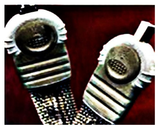
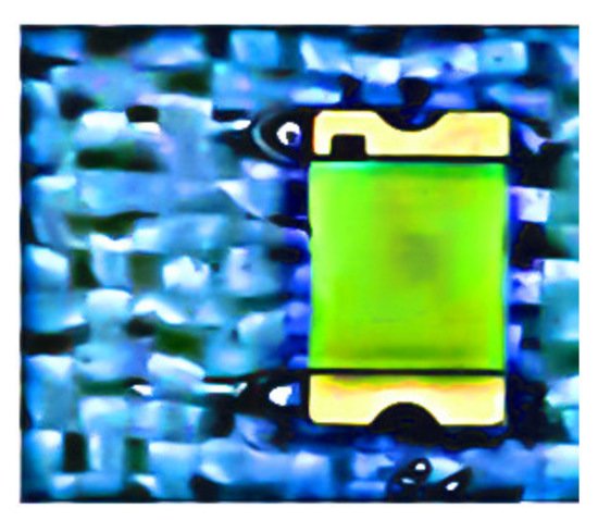
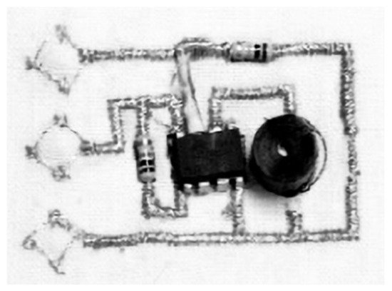
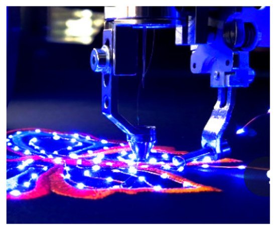
Modern electronic textiles are moving towards flexible wearable textiles, so-called e-textiles that have micro-electronic elements embedded onto the textile fabric that can be used for varied classes of functionalities. There are different methods of integrating rigid microelectronic components into/onto textiles for the development of smart textiles, which include, but are not limited to, physical, mechanical, and chemical approaches. The integration systems must satisfy being flexible, lightweight, stretchable, and washable to offer a superior usability, comfortability, and non-intrusiveness. Furthermore, the resulting wearable garment needs to be breathable.
1. Introduction
The term “smart textiles” is coined to designate an intelligent textile material and it covers a broad range of textiles. Smart textiles can be expressed as textile materials that are able to sense and respond to changes in their environment. Broadly, smart textiles are divided into passive and active smart textiles. Passive only observes, while active senses and reacts to the environmental changes [
1,
2].
Smart and wearable textiles are complete body-borne electronic systems with various functionalities of sensors which detect pressure [
3,
4], temperature and humidity [
5,
6], strain [
7], chemical and bio-sensors [
8,
9], data processing and networking [
10], mechanical actuation based on shape memory materials or electro-active polymers [
11], thermal and energy generation [
12,
13], as well as energy storage [
14,
15] and smart fashion [
16,
17]. These textiles also contribute to help communication such as health surveillance, safety, comfort, and leisure [
18].
Scholars have tried to develop wearable computers to simplify our lives, however, the challenge was how to incorporate computer hardware unobtrusively into/onto clothing materials [
19]. Common hardware is not comfortable enough during wearing due to its rigidity, high weight, and other discomfort qualities. Thorp [
20] stated that the first wearable electronic computer was developed in 1955 by Claude Shannon to calculate roulette probabilities. Then, Thorp and his co-workers developed wearable computers in 1961 by using switches in the shoe for input, acoustic output through a tiny earplug, and a small handmade computing unit worn on the belt to calculate roulette probabilities [
21]. The first wearable computer systematically produced came out in 1968, when Ivan Sutherland presented a head-mounted display using small cathode ray tube (CRT) displays placed in front of the user’s eyes [
22]. One of the pioneers in this field, Steve Mann, developed several prototypes using a near-eye display, an on-body computer, and a one-handed input devices [
23].
Ojuroye [
24] studied the design of a novel classification chart that measures the extent of electronic integration within textiles and this chart indicated how the level of electronic integration in textile impacts the degree of functionality, commercial viability, and industrial compatibility. Rambausek et al. [
25] discussed the five different levels of textile integration and its technical challenges per integration level. Bosowski et al. [
26] generally studied the three category levels of the integration of electronic components and circuits into/onto textiles which can be distinguished as textile-adapted, textile-integrated, and textile-based, as shown in
Figure 1.
Figure 1. Level of electronics integration in textile: (
a) textile-adapted, reprinted with permission from ref. [
26]. Copyright Elsevier license no. 5107701406893. (
b) textile-integrated, reprinted with permission from Taylor & Francis copy right license no. 501666551. (
c) textile-based, reprinted with permission from [
31]. Ghent University Textiles and Chemical Engineering.
The first type, the textile-adapted, refers to the manufacturing of special clothing accessories or extensions to contain electronic devices, so the electronic function is integrated by adding the actual rigid electronic device onto or into the garment (e.g., ICD+, communication devices for firemen and MP3 players) [
27,
28,
29]. The clothing and electronics are processed separately and merged at a later stage. Typically, the electronics can again be removed to allow washing and maintenance of the clothes, as shown in
Figure 1a. However, the textile being subjected to multiple mechanical deformations such as stretching and related characters. This puts lots of tension on any present interconnections via the textile between components and leads to lower reliability of the interconnection part of electronic device.
In the second type, the textile-integrated, the integration of the electronic components is done through the creation of an interconnection between the electronic elements and textile substrate, and often the textile material performs selected functionalities (e.g., a metal push buttons as on/off switch). Integration is at the fabric level, with circuits that can be partially fixed on the surface of/or inside the fabric [
30]. Here, conductive fiber interconnections have been sewn, stitched, printed, embroidered, and soldered into the fabric as shown in
Figure 1b. This kind of integration attains some level of flexibility and even stretchability, and is already more user friendly than textile-adapted solutions.
The last type of integration of electronic components is the textile-based which uses the textile structure itself to provide higher end electrical components within an electrical circuit embedded within the yarn or fiber. At the moment, these are mainly evidenced in research and in patents. No commercial products are out yet, but examples include in reference [
30] (e.g., electro-conductive or metallic-coated multifilament yarns forming an antenna, or a thermopile couple from nickel-coated carbon fibers to generate electricity [
31] (see
Figure 1c), and an electrochemical transistor (ECT) integrated into silk fiber) [
32].
2. Integration Techniques
At the early-stage developments of smart textile, technologies involved integration of electronics directly into/onto textile materials, this by applying different connection approaches between the rigid electronic components and soft textiles. In order to interconnect different electronics components such as conductive yarns, sensors, batteries, and processing circuits, the conductive tracks have to embed directly into/onto the textile. The most basic function of the chip-level interconnections is to provide electrical paths to and from the substrate for power and signal distribution.
The integration of electronics into/onto the textiles requires two straightforward connection steps. The first one is the mechanical connection to a textile material, while the second step is the electrical connection integrated on the conductive structures. Both connections must be functional and reliable.
2.1. Mechanical Connectors
In 1964, the first scientific paper concerning the mechanics of pressure connections was published by Whitley [
56]. The author gave a good overview and described the fundamental processes involved in crimping and force fit. In 1995, Mroczkowsk [
57] proposed a cold welding process for crimped connectors from Ag and Cu wire with a barrel (brass) surface that had large-area metal-to-metal contact, and would hold it there under any desired environmental condition for a long lifetime. To detect the extensive deformation of the conductors, the surface has been analyzed using SEM. Bernardoni et al. [
58] developed a low profile mechanical interconnect system having metalized loops and hoops for the creation of electronic connections. These crimp connections, as well as a good overview of crimping in general, has been published by Mroczkowski [
59].
A study on the reliability of crimp connections was published in 1978 containing a mathematical model and the factors which affect the reliability of crimp connections [
60] Optimization of the tool design, determination of parameters, effect of friction and comparison of implicit and explicit finite element methods to model crimp connections have been further investigated by different scholars [
61,
62]. Simon et al. [
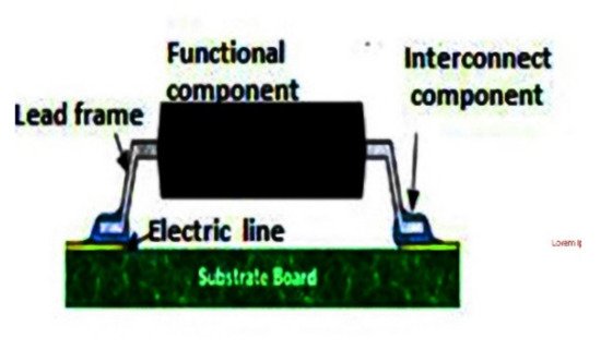
63] worked on the development of a multi-terminal crimp package for smart textile integration based on Crimp Flat Pack (CFP) which is a lead-frame-based electronic package that features crimp terminals for integrating electronics into textiles.
In addition to crimp beads, Kalhnayer et al. [
64] developed a mechanism of connection for antennas on textile substrates by the integration of the transponder through an interposer between chip and fabric. Although the processes seem suitable, it was not possible to achieve a permanent electrical contact and higher deformation of the antenna occurred.
Researchers in [
65,
66,
67,
68,
69,
70] described various approaches of physical attachments for electronic PCB (Printable Circuit Board) and wire with a textile by using different methods such as snap buttons, socket buttons, bolt connection, and ribbon cable connector, as shown in
Figure 2.
Figure 2. Physical attachments for electronic PCB fabric USB connector, reprinted with permission from ref. [
19]. Taylor & Francis with license no. 501667190.
In 2014, Seager and Chauraya [
71], studied the use of conductive hook and loop flexible and detachable connectors as the connector between the traditional electronics and a fabric system, and demonstrated how the electronics can be removed from a fabric system for security or other reasons such as washing. In 2015, Berglund and Duvall [
72], and Molla et al. [
73], introduced a novel technique for assembling surface-mount fabric PCBs using stitched traces and reflow soldering techniques. The results showed that all configurations were sufficiently durable for low-intensity wear, while, for high intensity wear, larger components and traces are needed to improve the durability.
Rubacha and Zięba [
74], developed and studied multifunctional magnetic fiber which were manufactured by introducing ferromagnetic nano-particle powders into the fiber matter during fiber production for use in Textronic products where the magnetic fibers may be used for the construction of textile magnetic coils. Scheulen et al. [
75] used adhesive bonded neodymium magnets for contacts in smart textiles. The electrical contact resistance between two magnets was found to be less than 0.01 Ohm. The magnets were glued to the textile using a conductive epoxy adhesive.
Righetti et al. [
76] integrated electronics onto fabric through gold-coated neodymium magnets which then bonded to the fabric through a commercial cyanoacrylate adhesive (CA). In this way, the authors developed a modular I2C-based wearable architecture where the garment provides the I2C bus made of four conductive wires. At different positions, modules were attached to the bus via magnetic connectors.
2.2. Soldering
Soldering interconnections between microelectronics and conductive textile material is a process in which two or more items are joined by melting a filler metal or solder and putting it into the joint [
77]. To be functional, the filler metal must have a lower melting point than the conductive thread or fabric and the microelectronics [
78]. Soldering is normally done above 200 °C, although low-temperature solder, with melting points as low as 150 °C [
79] or below, exist [
80,
81] and start to be common for textile integration.
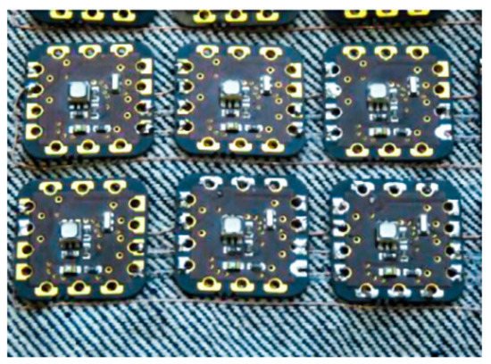
Soldering involves mounting the components directly onto the textiles surface. It is necessary to transfer thermal energy from a heat source to the soldering point to melt and flow the solder between terminals of the microelectronic component (known as solder pads) and conductive thread(s) in order to create good connections. In the soldering process, heat can be transferred either by conduction, convection, or radiation [
82]. In soldering, an additional material, called solder is used. The solders are soft alloys of lead (Pb), tin (Sn), or sometimes silver (Ag) that are used to join the metallic electrical components with the textile substrate, with Sn42Bi 58, a suitable alloy for textiles with melting point at 138 °C [
83]. Soldering achieves good electrical contact [
84]. The integration of the electronics on to textile substrate by soldering can usually be achieved by direct contact or frictional soldering [
85], hot air or thermal soldering [
86], ultrasonic soldering [
87,
88], laser soldering [
89], and infrared soldering [
90] as shown in
Figure 3 [
91].
Figure 3. Soldering of electronics and conductive wires on textile substrate, reproduced with permission from MDPI with creative common CC by license,
https://www.mdpi.com/openaccess, accessed on 13 July 2021 [
91].
Mostly, for textile materials, thermal bonding and ultrasonic soldering have been used. The advantage of friction bonding compared to thermal bonding is that the heat is generated directly at the joint. Localized heating reduces the risk of burning the surrounding nonconductive fabric material [
92].
Additionally, the soldering of smart textiles was investigated by different researchers such as Molla et al. [
73] who integrated LEDs into textile structures by soldering conductive uninsulated yarns. The LEDs were soldered to the exposed conductors, but in particular, the solder wicking along the multi-filament affected the durability of the joint and added stiffness to the textile. In addition, Mikkonen and Pouta [
93] studied the integration of electronics onto conductive wire by direct soldering and insertion into two layer weaving fabric. The distinct effect of the solder, especially, has an impact on the stiffness of the textile. All work steps were performed manually and were not fast enough. Overall, the contacting processes, manually and automatically, were still too slow and the conductors were not stretchable.
The developments of woven electrical circuits on to fabric using several microchips connected after copper conductors have been woven into a fabric connected by using resistive welding (using top-bottom probes and parallel gap welding) were formed at the cross-over points of orthogonal conductive yarns was studied by Dhawan [
94]. Furthermore, Atalay [
95] developed textile-based transmission lines using stainless steel and silver-plated conductive yarns, which were inserted between two layers of navy blue colored polyester fabric structure, without any undulation in a straight line via applying ultrasonic welding technology for e-textile applications. The results show that stainless steel yarns were simply affected in terms of conductivity change. The silver-plated yarns were found to be less suitable for ultrasonic welding technology. However, silver-plated yarns with higher linear density showed satisfactory results at moderate working conditions.
2.3. Sewing and Embroidering
Sewing and embroidery technologies are methods for interconnection of electronic components by attaching them on top of a textile fabric with yarn. T. Linz et al. [
96] stated that these methods are conventional techniques which consists of chip elements, PCB, and sensors that are placed on the substrate and attached by sewing to provide a rigid mechanical connection between the chip elements and conductive fabrics.
Temporary contacts and embroidered circuitry with conductive yarn has been demonstrated by Linz [
97]. The work focused on the interconnection process and studied machine embroidered electrical contacts. They suggested a solution to improve the reliability by using a conductive yarn embroidered through a metalized contact area on a flexible substrate which produced an electrical and mechanical connection.
Different authors, such as Linz and Christine [
98] and Hamdan and Voelker [
99], showed that common stitch embroidery technology can be used to integrate electronics on to textile in a light and cost efficient way. Embroidering mechanisms were used for flexible electronic modules using flexible conductive yarn interconnection with sensors, batteries, textile keyboards, and electrochemical biosensors [
100,
101].
Sahta et al. [
102] developed textile-based sewn switches by using commercially available conductive thread based on silver-coated multifilament polyamide thread and often used to connect devices within e-textile structures. Silver-coated multifilament polyamide yarns are elastic, flexible, and with respect to their textile properties, correspond to the “conventional” textile yarns. They are suitable for integration into the fabric structure by sewing. However, the thread used with a sewing machine as needle thread suitable are only 110dtex/f34x2-ply twisted yarns. Furthermore, the effects of washing on electrical conductivity of silver coated polyamide yarn was highly intensive [
103].
Post and Orth [
104] developed e-broidery (electronic embroidery in which the patterning of the conductive textiles is controlled by numerical sewing or weaving processes) as a means of creating computationally active textiles. The embroidery needle stitched through metalized contact areas of the substrate thereby making a mechanical and electrical interconnection with the conductive thread. The analysis of embroidery contacts for electronics in textile and investigation of ways to improve reliability of the embroidery contact on the textile have also been studied in [
105]. Christine et al. [
106] developed a fully integrated electrocardiogram shirt based on embroidered electrical interconnections with conductive yarn and miniaturized flexible electronics. Sewn electrode onto textile substrate using conductive stainless steel and polyester composite threads is shown in
Figure 4 [
107].
Figure 4. Integration and connection of microelectronics on textile substrate by embroidery, Reprinted with permission from ref. [
107]. Taylor & Francis with order no. 5107740253619.
Today, researchers have developed advanced embroidery machines to integrate electronics into the textile substrate. Advancements of Textile Research Facility TITV, from Greiz in Germany [
26], invented an embroidery technology using luminous sequins embroidered to conducting yarn, which is available on embroidery machine stich file (ZSK) embroidery machines with a ZSK sequin device. The sequin feeder apparatus includes at least two sequin feed units, each including a sequin feed mechanism, for feeding a continuous sequin strip toward a predetermined cutting position and a sequin-cutting cutter section located in the predetermined cutting position as shown in
Figure 5. One of the sequin feed units is selected and positioned in a predetermined sewing operation position, and the driving force of a feeding drive mechanism is transmitted to the sequin feed mechanism to feed out and integrate the sensor, LED sequins, and antenna on textile fabric. However, when embroidery is used, especially in near-body applications, the electronic and conductive paths have to be placed on the outside of the fabric, as they generally should be shielded from naturally occurring conductive substances such as sweat [
108]. Furthermore, the electronic components and conductive truck must not be damaged or lose efficiency by any external interruption such as abrasion and cyclic washing. Thermoplastic polyurethane was laminated over the embroidered conductive yarn to successfully protect it during washing. Applying encapsulation by using epoxy compound transfer, molding, adhesive film protection, and hot melt encapsulation to protect electric contacts is very common practice. It protects against mechanical stress, including temperature and induced mechanical stress. It also protects against chemicals such as moisture, salts, and atmospheric contaminants such as sulfur oxides (SO2) [
97].
Figure 5. ZSK automated LEDs sequin attachment device.
The main attention point with embroidery and sewing is that special yarn, and even needles, must be used, which allow embroidering without yarn breakage. Special yarns have been developed, e.g., Madeira high conductive thread (HC12) [
109], though further improvement in these yarns is still needed to obtain a wider range of conductivity, strength, and abrasion resistance. In addition, Silver-Tech 50 [
110], Nickel Conductive yarn [
111], Volt Smart Yarns, or CleverTex
® [
112] threads are also suitable for high resolution embroidery and have high resistance to washing cycle, which were used as a smart solution for wearable applications.
2.4. Hybrid Solder and Sewing Integration
In 2015, Bergluned et al. [
72] integrated microelectronics in the fabric by using a Brother PR650e embroidery machine in a hybrid solder and sewing technique. Three surface-mount LED packages (sizes 1 mm, 3 mm, and 5 mm) were attached to stitched conductive traces on 100% cotton fabric with a plain weave structure in two configurations, parallel with, and perpendicular to, the package axis, as shown in
Figure 6. The conductive traces were created using Syscom Liberator 40 silver coated Kururay
® Vectran conductive yarn, stitched in a lockstitch structure, using the embroidery machine and components, were attached manually using a reflow soldering process, with low-melt solder paste (Chip Quik).
Figure 6. Hybrid solder and stiches of electronics on to textile, reprinted with permission from ref. [
62]. Elsevier, with license no. 501667201.
The durability test was performed, using simulated every day wear testing, and showed that the surface-mount soldering of components to stitch conductors was a viable method of fabricating e-textile circuits. However, a challenge was excessive backstitching over the traces, extraneous or redundant stitched and thread trimming. These problems led to risk of electrical shorts, and the washing of the e-textile was found to be unsatisfactory.
2.5. Electrical Conductive Adhesive
Bonding involves applying conductive adhesives to embed components into/onto textile substrates. Conductive adhesives may be developed according to the end use application. Non-toxic, highly conductive, highly durable, and moderately flexible conductive adhesives can potentially be used to bond rigid components with flexible textile substrates [
113]. Joining also involves attaching an electronic component to a fabric by cyanoacrylate adhesive and applying (magnetic) force or heat on the fabric [
114,
115], as shown
Figure 7.
Figure 7. Connection of electronics by non-conductive adhesive onto textile reprinted with permission from ref. [
114]. Taylor & Francis order no. 501667217.
Conductive adhesives are widely used in the electronic packaging applications, such as die attach and solderless interconnections. For this purpose, different types of conductive adhesives for electronics packaging have been developed [
116,
117,
118]. Snacaktar et al. [
119] and Mehmann et al. [
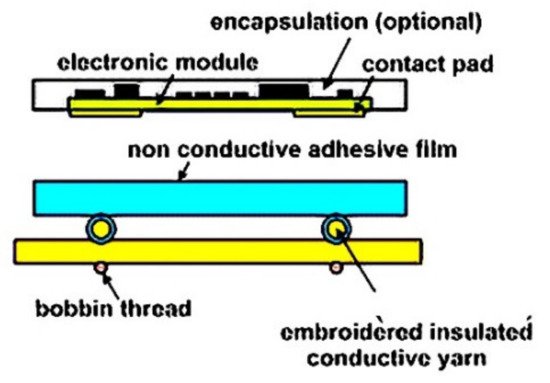
120] have studied epoxy-based adhesives used for joining electronics parts to fabric circuits. Krshiwoblozki et al. [
115] described electronic circuits connected with fabric by using thermoplastic polyurethanes nonconductive adhesive bonding. The thermoplastic adhesive bonding technology for bonding of electronic modules onto the textile substrates uses a thermoplastic nonconductive adhesive (NCA) film. The modules are placed onto textile circuits, with an NCA film in between, by applying pressure and heat. The adhesive melts and contact partners touch, as shown in
Figure 7 and
Figure 8.
Figure 8. Thermoplastic bonding electronics on to textile, Reprinted with permission from ref. [
122]. Elsevier, license no. 5107731320873.
Unlike other types of adhesives, electrically conductive adhesives perform two primary functions. First, conductive adhesives form joints with sufficient strength so that they can bind two surfaces, and secondly, an electrical interconnection was formed between the two bonded surfaces. This dual functionality is usually achieved in composite form by dispersion of particles in an insulating adhesive matrix [
116] by controlling the process parameter such as temperature, pressure, cure time, pot and shelf life, which are critical to the success of making reliable electrical and mechanical interconnections [
121]. Li and Wong [
122] applied conductive adhesives as a lead-free alternative in electronic packaging and interconnecting electronic material and in flip-chip assembly, chip scale package (CSP), and ball grid array (BGA) applications in replacement of solder. The recognized advantages of using electrical conductive adhesive ECA are improved environmental impact, gentler processing conditions (allowing the use of heat-sensitive and low-cost components and substrates), and fewer processing steps (reducing processing cost). However, this type of technology is not available easily and has challenging issues such as lower electrical conductivity, low conductivity fatigue resistance, limited current-carrying capability, and poor impact strength.
The conductive adhesive methods of joining electronics to conductive textiles is confronted with limitations including lower conductivity than solder methods, sensitivity to the type and quality of component and board metallization, requiring longer time to cure, and possessing lower durability in various climatic environments [
123]. One issue is thermal stress caused by coefficient of thermal expansion mismatch between the conductive textile and electrical component, while other attention points are mismatched between the adhesive and adherent during temperature cycling, oxidation of the bonding surfaces and of the filler, and degradation by UV-light or corrosive gases [
124,
125,
126].
2.6. Inkjet and 2D Screen-Printing
Another method for practical integration of electronics onto textiles substrate is printing textile-based electronics onto the surface of the substrate. This can be performed by primary printing techniques, such as screen printing or inkjet printing [
127]. Examples of smart textiles achieved by printing techniques are piezo resistive layers [
128], a textile transmission line [
129], heating device [
130,
131], a frequency selective surface [
132], a secured traceability tag [
133], an auto touch pad [
134,
135], highly deformable electro chromic device and electrochromic e-skin [
136,
137,
138], organic light-emitting diodes [
139,
140,
141], microchips such as RFID tags [
142,
143,
144], resistors and capacitor [
145] flexible heated circuits [
146,
147], antenna [
148,
149,
150], and piezo sensitive materials [
151].
Today, various electro active functional inks allow the manufacturing of textile based electronic devices. Several researchers have developed printable conductive inks for screen printing that can form interconnections [
152,
153,
154,
155]. They showed that these wearable electronics were rigid and inflexible electronic technologies that offer limited skin-compatibility and are damaged under washing. The resultant e-textiles were too uncomfortable to wear because they were not breathable.
In 2017, Carey et al. [
156] developed an ink based on graphene and other two-dimensional materials that enable the printing of washable and biocompatible electronics on textiles such as cotton and polyester. Cao et al. [
157] also developed washable, breathable, and designable electrodes through screen-print carbon nanotube (CNT) ink, which not only had excellent flexibility and stability but also relatively low surface resistivity (0.2 kΩ/sq.) and air permeability (88.2 mm/s).
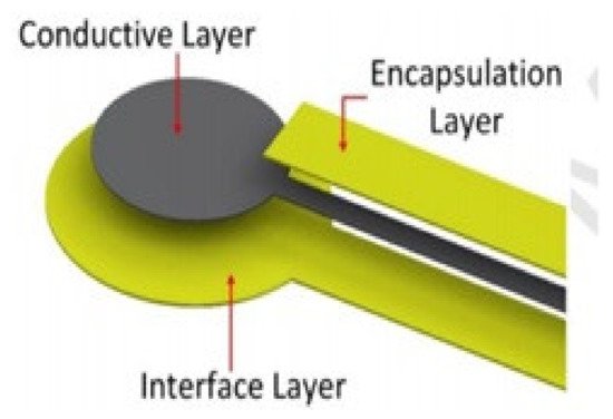
Paul et al. [
158] developed an innovative washable screen-printed network of electrodes associated with conductive tracks on textiles for medical applications as shown in
Figure 9. A polyurethane paste was screen printed onto a woven textile to create a smooth and high surface energy interface layer. Subsequently, a silver paste was printed on top of this interface layer to provide a conductive track and a final polyurethane encapsulation layer was placed to protect the conductive track from abrasion and creasing.
Figure 9. Screen printing fabrication for conductive tracks, reprinted with permission from ref. [
158]. Elsevier with license no. 5107681074985.
Researchers [
159,
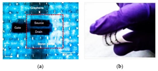
160] have also overcome the limitations of washability by developing low-boiling point inks based on nano scale platelets of graphene and hexagonal boron nitride (h-BN) suspended in organic solvents that were compatible with inkjet printers. The researchers printed stacks of inks based on different two-dimensional materials onto cotton and polyester fabrics to create electronic components such as amplifiers, programmable memories, logic circuits, and integrated circuits, as illustrated in
Figure 10. The papers showed that one of the problems with current approaches to inkjet printing onto a two-dimensional material is that commonly used solvents have a low-boiling point and are toxic.
Figure 10. Graphene based biocompatible electronics. Optical microscopy image of the inverted FET on polyester (
a). Image of an array of FETs on textile (
b), reprinted with permission from ref. [
156]. Springer Nature
http://creativecommons.org/licenses/by/4.0/ accessed on 13 July 2021.
This entry is adapted from the peer-reviewed paper 10.3390/ma14175113

