The global system is illustrated in Figure 1. It is based on a WT-DFIG system, directly interconnected to the AC grid by the DFIG stator. On the other side, its rotor is attached via an indirect converter from the grid. It consists of two power converters, which are connected to DC bus. The first converter (I) is an inverter of three levels attached to the DFIG rotor, and the second converter (II) is attached to the grid and controlled by another method. The second converter controls its output to obtain a unit power factor operation, sinusoidal voltages, and currents with a constant frequency.
- grid-connected wind turbine conversion
- random behavior wind speed
1. Wind Turbine Working Zones Description
The wind turbine with variable speeds works in different operating zones as presented in [1]. Zone I is a region where the wind speed is low, to begin the energy production for economic reasons. Zone II is where the WT receives wind with a speed bigger than cut-in speed, the system works with MPPT algorithm to extract maximum power with null angle pitch. Zone III is described as when the wind speed exceeds the nominal operation mode; the system works under pitch angle control to limit the produced output power to its nominal value by varying angle pitch β. In zone IV, once the maximum wind speed is reached, the DFIG rotor is disconnected from the turbine, therefore interrupting the power generation [1].
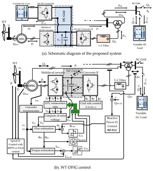
Figure 1. Global control scheme.
2. Maximum Power Point Tracking Description
In zone II, the power characteristic curve of a wind turbine’s wind turbine is non-linear, its parabolic shape allows the power coefficient to be at its maximum (Cp-max) for an optimal speed ratio (λopt) and a null blade angle (β = 0°) [1][2]. The speed of the DFIG is enslaved to a reference from an MPPT algorithm for maximum tracking of wind power.
3. Pitch Angle Control Description
In zone III, the control of WT angle blades limits the delivered power to its nominal value when the system works overspeed, while the extraction power maximization means that the power produced is regulated according to its speed, in order to protect the power converters and the electrical generator, so the PI regulator insures the generation of Tem-ref to increase the blade angle (β), keeps the power at the nominal value, and decreases the speed ratio (λ) and the power coefficient (Cp) [1].
4. Description of the Proposed Direct Reactive Power Control
4.1. Direct Torque Control of the Three-Level Inverter Description
Reference [3] describes the characteristic of the wind turbine and the operating zones from which the principles of MPPT and pitch control are taken.
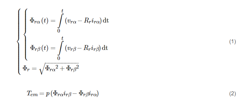
The DTC of the DFIG is based on the control of the rotor flux and the value of the electromagnetic torque. The rotor flux and the electromagnetic torque are estimated from the rotor flux components along the α and β axes [3][1], as given in Equations (1) and (2).
To analyze the voltage generated by the three-level inverter, each arm is mapped by three switches that allow the inputs of the stator to connect to the source voltage (represented by Vdc/2, 0 and −Vdc/2).
The transformation of voltages from the natural three phases into bi-phases (α-β) gives voltage vectors associated to the stator flux position. The vector’s various state number is 19 since some of the 27 possibilities yield the same voltage vector. The presentation of all voltage vectors of the three-level inverter in the bi-phasic frame is shown in Figure 2.
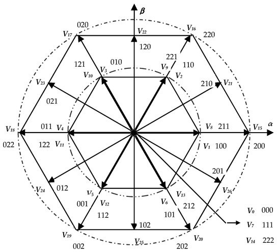
Figure 2. Scheme of three-level inverter voltage vectors.
The space of the three-level inverter voltage vectors must be divided into 12 sectors instead of 6 using the diagonal between the long vector and the adjacent medium. The appropriate vector is chosen based on the torque and the flux errors from all 19 different available vectors, Figure 2.
The implementation of DTC to the studied system is accomplished by selecting the optimal vector and applying it to the three-level inverter. In order to establish the control with the proposed topology, first, the estimated values of torque and flux are compared with the references, and then the errors are digitized out of the hysteresis regulators, five-level and three-level comparators, respectively, which gives the variable flux (Cflx) and the variable torque (Ctrq). The number of sector N is determined using the α-β rotor flux component. If the torque comparator output is high or equal to two, the inverter state is considered high, otherwise the state is considered low. For the torque regulation, the use of a five-level hysteresis comparator permits the ability to have both rotation directions of the rotor flux compared to the stator flux. The output of this regulator is represented by a Boolean variable, Ctrq, indicating if the torque needs be raised (Ctrq = 2 or = 1), reduced (Ctrq = −2 or = −1), or kept constant (Ctrq = 0). For rotor flux control, a three-level hysteresis comparator could be used. Therefore, the rotor flux magnitude Φr is able to be controlled. The output of the flux regulator is also represented by a Boolean variable, Cflx, indicating if the flux needs be raised (Cflx = 1), reduced (Cflx = −1), or kept constant (Cflx = 0) to preserve it: |Φr_ref − Φr| ≤ ∆Φr.
The switching table of the three-level inverter DTC is presented in Table 1. This table is considered to select the appropriate vector using the information described above (numerical errors of flux Cflx and torque Ctrq, and the number of sector N). When the impact of each voltage vector is analyzed, it may be observed that the vector impacts the torque and flux with the modulus and vector direction changes. The null voltage vectors (V0, V7, and V14) are selected alternately, in order to minimize the number of switches in the inverter arms [4].
Table 1. The switching table of DTC three-level inverter DFIG.
| Cflx | Ctrq | N | |||||||||||
|---|---|---|---|---|---|---|---|---|---|---|---|---|---|
| 1 | 2 | 3 | 4 | 5 | 6 | 7 | 8 | 9 | 10 | 11 | 12 | ||
| +1 | +2 | V21 | V16 | V22 | V17 | V23 | V18 | V24 | V19 | V25 | V20 | V26 | V15 |
| +1 | V21 | V2 | V22 | V3 | V23 | V4 | V24 | V5 | V25 | V6 | V26 | V1 | |
| 0 | Zero vector | ||||||||||||
| −1 | V26 | V1 | V21 | V2 | V22 | V3 | V23 | V4 | V24 | V5 | V25 | V6 | |
| −2 | V26 | V15 | V21 | V16 | V22 | V17 | V23 | V18 | V24 | V19 | V25 | V20 | |
| −1 | +2 | V17 | V23 | V18 | V24 | V19 | V25 | V20 | V26 | V15 | V21 | V16 | V22 |
| +1 | V3 | V23 | V4 | V24 | V5 | V25 | V6 | V26 | V1 | V21 | V2 | V22 | |
| 0 | Zero vector | ||||||||||||
| −1 | V5 | V25 | V6 | V26 | V1 | V21 | V2 | V22 | V3 | V23 | V4 | V24 | |
| −2 | V19 | V25 | V20 | V26 | V15 | V21 | V16 | V22 | V17 | V23 | V18 | V24 | |
| 0 | +2 | V22 | V17 | V23 | V18 | V24 | V19 | V25 | V20 | V26 | V15 | V21 | V16 |
| +1 | V22 | V3 | V23 | V4 | V24 | V5 | V25 | V6 | V26 | V1 | V21 | V2 | |
| 0 | Zero vector | ||||||||||||
| −1 | V25 | V6 | V26 | V1 | V21 | V2 | V22 | V3 | V23 | V4 | V24 | V5 | |
| −2 | V25 | V20 | V26 | V15 | V21 | V16 | V22 | V17 | V23 | V18 | V24 | V19 | |
4.2. The Proposed Fuzzy PID Design and Local Reactive Power Compensation Description
The PID controller is designed using the fuzzy logic controller (FLC) based on Mamdani inference. There are two FLCs; the first is utilized for the generation of electromagnetic torque reference in the speed loop. The second is for the reactive power loop to create the rotor flux reference. Figure 3 shows the proposed fuzzy PID (F-PID) diagram.
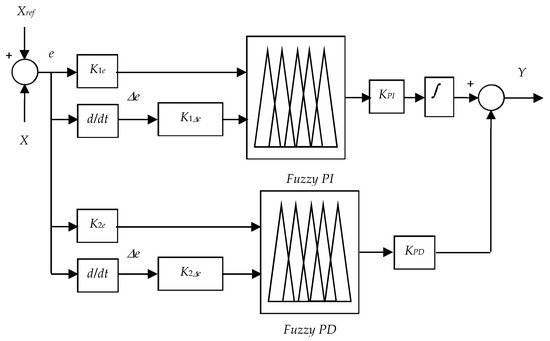
Figure 3. Scheme of the proposed fuzzy PID for the two loops: speed and reactive power loops.
In the first loop (the speed loop): X represents the DFIG mechanical speed (Ω) and Xref represents its reference (Ωref), while the output of this loop (Y) will be the electromagnetic torque reference (Tem-ref). In the second loop (the reactive power loop): X represents the estimated reactive power (QAC) and Xref represents its reference (QAC-ref) (it is the demand in reactive power of the AC grid), the output of this loop (Y) is the reference of the rotor flux (Φr-ref).
K1e, K1Δe, and KPI are scaling factors of the fuzzy PI, and K2e, K2Δe, and KPD are scaling factors of the fuzzy PD. e and Δe are the error and its derivative, respectively.
It is well known that fixed gains are very sensitive when the system is exposed to parameter uncertainties and external disturbances. Thus, to overcome this problem and to compute an optimal controller, a fuzzy controller is introduced as a supervisor to compute the damping gains of the PI and PD controllers that are considered the outputs of the fuzzy supervisor to overcome the problem caused by parameter uncertainties which makes the proposed strategy intelligent. The selected fuzzy control design process consists of: fuzzification of the inputs, formulation of the rules, and finally defuzzification of the output. Triangular and trapezoidal types symmetrically and uniformly distributed are used to select the membership functions. The proposed F-PID is built using two different FLCs, the first is fuzzy PI (F-PI) and the other is fuzzy PD (F-PD). Figure 4 presents the fuzzification membership functions (MFs) of inputs and outputs of both FLCs. Moreover, the fuzzy rules are presented in Table 2 for the first regulator F-PI and Table 3 for the second regulator F-PD. Finally, the method of center of gravity (CoG) is invested for the defuzzification of both FLCs as its the most commonly used defuzzification method, also commonly referred to as the centroid method. This method determines the center of area of a fuzzy set and returns the corresponding crisp value [5][2].
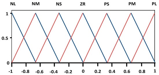
Figure 4. MFs of F-PID’s inputs and outputs.
Table 2. Fuzzy rules of F-PI.
| de/e | NL | NM | NS | ZR | PS | PM | PL |
| NL | NL | NL | NL | NL | NM | NS | ZR |
| NM | NL | NL | NL | NM | NS | ZR | PS |
| NS | NL | NL | NM | NS | ZR | PS | PM |
| ZR | NL | NM | NS | ZR | PS | PM | PL |
| PS | NM | NS | ZR | PS | PM | PL | PL |
| PM | NS | ZR | PS | PM | PL | PL | PL |
| PL | ZR | PS | PM | PL | PL | PL | PL |
Table 3. Fuzzy rules of F-PD.
| de/e | NL | NM | NS | ZR | PS | PM | PL |
| NL | NL | NL | NL | NL | PS | PS | PS |
| NM | NL | NL | NL | NM | PS | PS | PS |
| NS | NL | NL | NM | NS | PS | PS | PM |
| ZR | NL | NM | NS | ZR | PS | PM | PL |
| PS | NM | NS | NS | PS | PM | PL | PL |
| PM | NS | NS | NS | PS | PM | PL | PL |
| PL | NS | NS | NS | PS | PL | PL | PL |
The control of the DC/AC converter (II) imposes at the output a unit power factor with a constant frequency at 50 Hz, while the reactive power is provided by the DFIG.

where Qs depicts the DFIG’s stator reactive power, QL-AC depicts the reactive powers exchanged with the AC load, QAC depicts AC grid reactive power, Qrg depicts the reactive power transferred via the second converter (II) (DC/AC), and ϕL-AC depicts the local load phase.
This entry is adapted from the peer-reviewed paper 10.3390/su13169060
References
- Tamalouzt, S.; Idjdarene, K.; Rekioua, T.; Abdessemed, R. Direct Torque Control of Wind Turbine Driven Doubly Fed Induction Generator. Rev. Roum. Sci. Tech. Electrotech. Energ. 2016, 61, 244–249.
- Tamalouzt, S.; Rekioua, T.; Abdessemed, R. Direct torque and reactive power control of Grid Connected Doubly Fed Induction Generator for the wind energy conversion. In Proceedings of the 2014 International Conference on Electrical Sciences and Technologies in Maghreb (CISTEM), Tunis, Tunisia, 3–6 November 2014; pp. 1–7.
- Tamalouzt, S.; Benyahia, N.; Rekioua, T.; Abdessemed, R. Performances analysis of WT-DFIG with PV and fuel cell hybrid power sources system associated with hydrogen storage hybrid energy system. Int. J. Hydrogen Energy 2016, 41, 21006–21021.
- Nami, A.; Liang, J.; Dijkhuizen, F.; Demetriades, G.D. Modular Multilevel Converters for HVDC Applications: Review on Converter Cells and Functionalities. IEEE Trans. Power Electron. 2015, 30, 18–36.
- Shihabudheen, K.V.; Pillai, G.N.; Raju, S.K. Neuro-Fuzzy Control of DFIG Wind Energy System with Distribution Network. Electr. Power Compon. Syst. 2018, 46, 1416–1431.