Microcellular injection moulding (MuCell®) is a polymer processing technology that uses a supercritical fluid inert gas, CO2 or N2, to produce light-weight products. Due to environmental pressures and the requirement of light-weight parts with good mechanical properties, this technology recently gained significant attention. However, poor surface appearance and limited mechanical properties still prevent the wide applications of this technique.
- mechanical properties
- microcellular injection moulding
- MuCell
- polymer processing
- processing parameters
- surface quality
1. Introduction
Most plastics are fossil-based, and there are significant concerns regarding the environmental impact of their use. However, researchers are making significant progress regarding the development of bio-based polymers that represent around 1% of the total market [1][2]. Plastic parts can be produced through a wide range of techniques, such as injection moulding, compression moulding, extrusion, blow-moulding, thermoforming, and reaction-injection moulding [3][4][5][6]. Among these technologies, injection moulding is the most relevant technique.
-
Plastic injection;
-
Holding and packing;
-
Cooling and solidification;
-
Mould opening and part ejection.
Figure 1 shows the average percentage of each phase over the overall injection moulding cycle [10]. The total cycle depends on different factors, of which the part wall thickness is one of the most relevant. Nevertheless, the cooling stage is always the more time-consuming step, representing more than half of the injection moulding cycle.
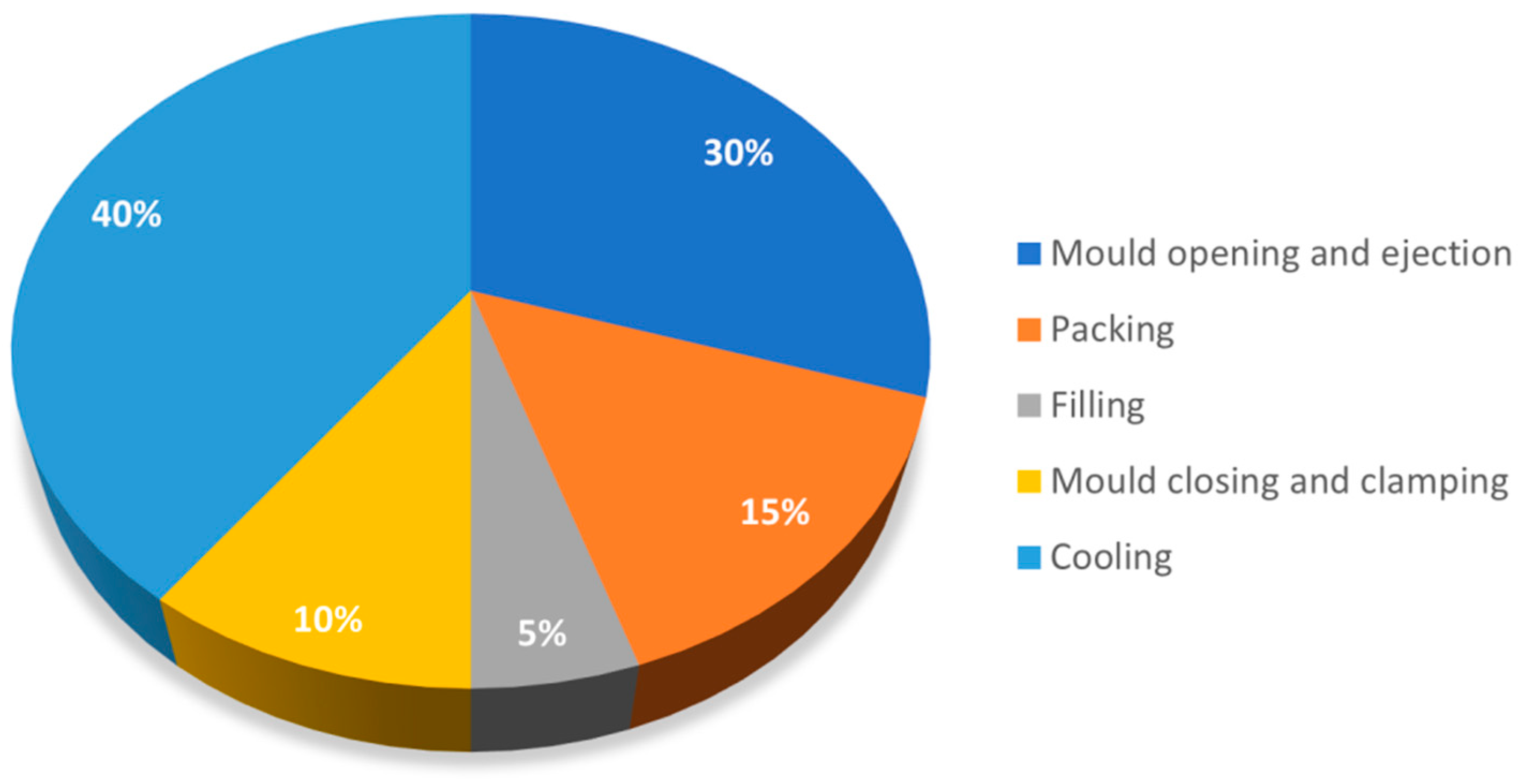 Figure 1. The cycle time of injection moulding (figure adapted from [10]).
An important market for injection moulding parts is the automotive sector. In the European Union (EU), this is a sector under significant safety and environmental regulations. Restrictions on CO 2 emissions imposed by the EU led not only to the development of new-energy powered vehicles, such as hybrid and electric vehicles, but also to the development of more efficient and light-weight gasoline-powered vehicles. Therefore, the automotive industry is increasingly demanding high-performance and light-weight plastic parts. Thus, injection moulding companies supplying plastic parts for the automotive sector are facing significant challenges, as current injection moulded parts must be redesigned, and new injection moulding strategies are required.
Replacing solid injected moulded parts by foamed ones represents an effective way to reduce part weight [11][12][13]. Thermoplastic foaming parts can be produced using two types of blowing agents: chemical and physical blowing agents [12][14][15]. In the case of chemical blowing agents, the agents are mixed with the polymeric materials in the hopper and moved into the barrel. When the temperature reaches a certain value, gas such as nitrogen, carbon dioxide, or carbon monoxide is released, creating an internal microcellular structure [16][17]. The main disadvantages of using chemical blowing agents are related to uneven bubble formation and difficulties in dealing with the remaining chemical by-products in the machine [17].
The microcellular injection moulding is a foaming technology that uses a physical blowing agent. MuCell® was the first commercialised microcellular injection moulding process being also the most known technique [13][18]. However, other technologies were recently developed and commercialised such as Optifoam®, ProFoam®, Ergocell® [13][18][19], and IQ Foam® [20]. All of these technologies are based on the mixture of a gas/supercritical fluid (SCF) and the melt during the injection moulding process, but involving different mixture methods [13][18][19][20]. In the MuCell® process, a specially designed reciprocating screw is used as the SCF dosage element. This screw, longer than a conventional one, is equipped with a mixing section designed to optimise the SCF-polymer melt. The Optifoam® process uses a specially designed nozzle as the SCF dosage equipment. In the ProFoam® process, the gas is put into the hopper straight and dissolves with the melt inside the injection unit, while in the Ergocell® process, a dynamic mixer is used for mixing SCF with the melt. Finally, in the IQ Foam® process, a two-chambered unit is set up between the hopper and the screw chamber to make the melt and gas mix at moderate-low pressures [13][18][19][20]. Among these technologies, MuCell® has the highest industrial acceptance and is the leading technology. These technologies, and MuCell® in particular, allow not only to produce light-weight plastic parts but also to reduce carbon footprint and CO2 emissions [21].
2. Prospects
| Material | Parameters | Changes | Morphology | Skin Thickness | Apparent Density | Weight Reduction | Warpage | Mechanical Properties | Reference | |||||||||
|---|---|---|---|---|---|---|---|---|---|---|---|---|---|---|---|---|---|---|
| Tensile | Impact | Flexural | Biaxial Bending | |||||||||||||||
| Cell Size | Cell Number (Density) | Elastic Modulus | Yield Strength | Tensile Strength | Young’s Modulus | Flexural Strength | Bending Stiffness | Maximum Force | Energy | |||||||||
| ABS | shot volume | ↓ | ↓ | ↑ | ↓ | ↓ | ↑ | ↓ | ↓ | [23] | ||||||||
| SCF content | ↑ | ↓ | ↑ | ↓ | ↓ | ↓ | ||||||||||||
| mould temperature | ↑ | ↓ | ↑ | ↑ | no | no | no | |||||||||||
| injection velocity | ↑ | ↓ | ↑ | ↓ | no | no | no | |||||||||||
| PP/GF | mould temperature | ↑ | ↓ | no | no | no | no | ↓ | ↓ | [24][25] | ||||||||
| degree of foaming | ↓ | ↑ | ↑ | ↓ | ↓ | ↓ | ||||||||||||
| injection speed | not clear | |||||||||||||||||
| delay time | ↓ | ↓ | ↓ | ↓ | ↓ | ↑ | ↑ | |||||||||||
| gas content | ↓ | ↑ | no | |||||||||||||||
| MuCell process pressure (MPP) | ||||||||||||||||||
| shot volume | ↓ | ↓ | ↓ | ↓ | ↓ | ↓ | ||||||||||||
| PP, PP/CaCo3, ABS | SCF content | ↑ | ↓ | ↓ | ↓ | [26] | ||||||||||||
| PEI | shot size | ↑ | ↓ | ↑ | ↑ | ↓ | ↑ | ↑ | ↑ | [27] | ||||||||
| SCF content | ↑ | ↑ | ↓ | ↓ | ↑ | ↓ | ↓ | ↓ | ||||||||||
| injection speed | ↑ | ↓ | ↑ | ↑ | ↓ | ↑ | ↑ | ↑ | ||||||||||
| mould temperature | ↑ | ↓ | ||||||||||||||||
| PPS/GF | injection speed | ↑ | no | no | ↓ | no | no | [28] | ||||||||||
| PPS | shot size | ↑ | ↓ | ↑ | ↑ | ↑ | ↑ | ↑ | ↑ | [29] | ||||||||
| SCF content | ↑ | ↓ | ↑ | no | no | no | ||||||||||||
| TPU | plasticising temperature | ↑ | ↑ | ↑ until 200 °C then ↓ | ↑ until 198 °C then ↓ | [30] | ||||||||||||
| injection speed | ↑ | ↓ | ↑ until 45 ccm/s then ↓ | ↑ until 40 ccm/s then ↓ | ||||||||||||||
| injection volume | ↓ | |||||||||||||||||
| SCF content | ↓ | ↑ | ↓ | no | ||||||||||||||
| HDPE/Wood fibre | gas content | ↑ | ↑ | [31] | ||||||||||||||
| injection speed | ↑ | ↑ | ||||||||||||||||
| mould temperature | ↑ | |||||||||||||||||
| weight reduction | ↓ | ↑ | ↑ | ↑ | ||||||||||||||
| PC | melt temperature | ↑ | ↑ | ↑ | [32][33] | |||||||||||||
| mould temperature | ↑ | ↑ | ↓ | |||||||||||||||
| MPP | ↑ | no | ↓ | |||||||||||||||
| SCF content | ↑ | ↑ | not clear | |||||||||||||||
| injection rate | ↑ | ↑ | not clear | |||||||||||||||
| shot size | ↑ | ↑ | not clear | |||||||||||||||
| PA66/GF | injection temperature | ↑ | ↓ | ↑ | [34] | |||||||||||||
| gas injection pressure | ↑ | ↓ | ↑ | ↑ | ||||||||||||||
| PA6 | shot size | ↑ | ↓ | ↓ | ↑ | [35] | ||||||||||||
| melt temperature | ||||||||||||||||||
| SCF content | ||||||||||||||||||
| injection speed | ||||||||||||||||||
| PA6/Clay | shot size | ↑ | ↑ until 18.4 mm then ↓ | ↑ until 18.4 mm then ↓ | ↑ | [35] | ||||||||||||
| melt temperature | ↑ | no | no | |||||||||||||||
| SCF content | ↑ | no | no | |||||||||||||||
| injection speed | ↑ | no | no | |||||||||||||||
| PP/GF | SCF content | ↑ | ↓ | ↓ | [36] | |||||||||||||
| PP/talc | SCF content | ↑ | ↓ | [22] | ||||||||||||||
| PS | mould temperature | ↑ | ↑ | no | ↓ | ↓ | ↓ | [37][38] | ||||||||||
This entry is adapted from the peer-reviewed paper 10.3390/ma14154209
References
- European Bioplastics. Bioplastics—Facts and Figures; European Bioplastics: Berlin, Germany, 2019.
- Wang, G.; Zhao, G.; Dong, G.; Mu, Y.; Park, C.B. Lightweight and strong microcellular injection molded PP/talc nanocomposite. Compos. Sci. Technol. 2018, 168, 38–46.
- Faruk, O.; Bledzki, A.K.; Matuana, L.M. Microcellular foamed wood-plastic composites by different processes: A review. Macromol. Mater. Eng. 2007, 292, 113–127.
- Ramos-De Valle, L.F. Principles of polymer processing. In Handbook of Polymer Synthesis, Characterization, and Processing, 1st ed.; Saldívar-Guerra, E., Vivaldo-Lima, E., Eds.; John Wiley & Sons: Hoboken, NJ, USA, 2013; pp. 451–461.
- Tadmor, Z.; Gogos, C.G. Principles of Polymer Processing, 2nd ed.; John Wiley & Sons: Hoboken, NJ, USA, 2013; pp. 1–984.
- Pearson, J.R. Mechanics of Polymer Processing; Springer Science & Business Media: Dordrecht, The Netherlands, 1985; pp. 1–712.
- Fernandes, C.; Pontes, A.J.; Viana, J.C.; Gaspar-Cunha, A. Modeling and optimization of the injection-molding process: A Review. Adv. Polym. Technol. 2018, 37, 429–449.
- Khosravani, M.R.; Nasiri, S. Injection molding manufacturing process: Review of case-based reasoning applications. J. Intell. Manuf. 2020, 31, 847–864.
- Rosato, D.V.; Rosato, M.G. Injection Molding Handbook, 3rd ed.; Springer Science & Business Media: New York, NY, USA, 2012; pp. 1–1460.
- Goodship, V. 4—Injection molding of thermoplastics. In Design and Manufacture of Plastic Components for Multifunctionality; Goodship, V., Middleton, B., Cherrington, R., Eds.; William Andrew Publishing: Oxford, UK, 2016; pp. 103–170.
- Okolieocha, C.; Raps, D.; Subramaniam, K.; Altstädt, V. Microcellular to nanocellular polymer foams: Progress (2004–2015) and future directions—A review. Eur. Polym. J. 2015, 73, 500–519.
- Banerjee, R.; Ray, S.S. Foamability and special applications of microcellular thermoplastic polymers: A review on recent advances and future direction. Macromol. Mater. Eng. 2020, 305, 2000366.
- Xu, J. Microcellular Injection Molding; John Wiley & Sons: Hoboken, NJ, USA, 2011; pp. 1–632.
- Štěpek, J.; Daoust, H. Chemical and physical blowing agents. In Additives for Plastics; Springer: New York, NY, USA, 1983; Volume 5, pp. 112–123.
- Iannace, S.; Park, C.B. Biofoams: Science and Applications of Bio-Based Cellular and Porous Materials; CRC Press: Boca Raton, FL, USA, 2015; pp. 1–466.
- Han, C.D.; Kim, Y.W.; Malhotra, K.D. A study of foam extrusion using a chemical blowing agent. J. Appl. Polym. Sci. 1976, 20, 1583–1595.
- Kutz, M. Applied Plastics Engineering Handbook: Processing and Materials; Elsevier Science: Amsterdam, The Netherlands, 2011; pp. 1–574.
- Wang, G.; Zhao, G.Q.; Wang, J.; ZHANG, L. Research on formation mechanisms and control of external and inner bubble morphology in microcellular injection molding. Polym. Eng. Sci. 2015, 55, 807–835.
- Błędzki, A.K.; Faruk, O.; Kirschling, H.; Kuehn, J.; Jaszkiewicz, A. Microcellular polymers and composites. Polimery 2006, 51, 697–703.
- Gómez-Monterde, J.; Hain, J.; Sanchez-Soto, M.; Maspoch, M.L. Microcellular injection moulding: A comparison between MuCell process and the novel micro-foaming technology IQ Foam. J. Mater. Process. Technol. 2019, 268, 162–170.
- Elduque, D.; Clavería, I.; Fernández, Á.; Javierre, C.; Pina, C.; Santolaria, J. Analysis of the influence of microcellular injection molding on the environmental impact of an industrial component. Adv. Mech. Eng. 2014, 6, 793269.
- Kramschuster, A.; Cavitt, R.; Ermer, D.; Chen, Z.; Turng, L.S. Quantitative study of shrinkage and warpage behavior for microcellular and conventional injection molding. Polym. Eng. Sci. 2005, 45, 1408–1418.
- Gómez-Monterde, J.; Sánchez-Soto, M.; Maspoch, M.L. Influence of injection molding parameters on the morphology, mechanical and surface properties of ABS foams. Adv. Polym. Technol. 2018, 37, 2707–2720.
- Kastner, C.; Steinbichler, G.; Kahlen, S.; Jerabek, M. Influence of process parameters on mechanical properties of physically foamed, fiber reinforced polypropylene parts. J. Appl. Polym. Sci. 2018, 136, 47275.
- Gómez-Monterde, J.; Sánchez-Soto, M.; Maspoch, M.L. Microcellular PP/GF composites: Morphological, mechanical and fracture characterization. Compos. Part A Appl. Sci. Manuf. 2018, 104, 1–13.
- Febra, M.; Vasco, J.; Capela, C. Mechanical characterization of thermoplastic polymers foamed by microcellular injection moulding. In Proceedings of the PMI 2018—Polymers and Moulds Innovations, Guimaraes, Portugal, 19–21 September 2018.
- Li, J.; Chen, Z.; Wang, X.; Liu, T.; Zhou, Y.; Luo, S. Cell morphology and mechanical properties of microcellular mucell® injection molded polyetherimide and polyetherimide/fillers composite foams. J. Appl. Polym. Sci. 2013, 130, 4171–4181.
- Lohr, C.; Beck, B.; Henning, F.; Weidenmann, K.A.; Elsner, P. Process comparison on the microstructure and mechanical properties of fiber-reinforced polyphenylene sulfide using MuCell technology. J. Reinf. Plast. Compos. 2018, 37, 1020–1034.
- Liu, T.; Liu, H.; Li, L.; Wang, X.; Lu, A.; Luo, S. Microstructure and properties of microcellular poly (phenylene sulfide) foams by Mucell injection molding. Polym. Plast. Technol. Eng. 2013, 52, 440–445.
- Mi, H.Y.; Jing, X.; Peng, J.; Turng, L.S.; Peng, X.F. Influence and prediction of processing parameters on the properties of microcellular injection molded thermoplastic polyurethane based on an orthogonal array test. J. Cell. Plast. 2013, 49, 439–458.
- Yoon, J.; Kuboki, T.; Jung, P.; Wang, J.; Park, C. Injection molding of wood-fiber/plastic composite foams. Compos. Interfaces 2009, 16, 797–811.
- Chen, S.C.; Yang, J.P.; Hwang, J.S.; Chung, M.H. Effects of process conditions on the mechanical properties of microcellular injection molded polycarbonate parts. J. Reinf. Plast. Compos. 2008, 27, 153–165.
- Hwang, S.; Chen, S.; Chung, M. Study on the mechanical properties of microcellular injection molded parts. In Proceedings of the ANTEC, Boston, MA, USA, 1–5 May 2005.
- Volpe, V.; Lanzillo, S.; Affinita, G.; Villacci, B.; Macchiarolo, I.; Pantani, R. Lightweight high-performance polymer composite for automotive applications. Polymers 2019, 11, 326.
- Yuan, M.; Turng, L.S.; Gong, S.; Caulfield, D.; Hunt, C.; Spindler, R. Study of injection molded microcellular polyamide-6 nanocomposites. Polym. Eng. Sci. 2004, 44, 673–686.
- Kim, H.K.; Sohn, J.S.; Ryu, Y.; Kim, S.W.; Cha, S.W. Warpage reduction of glass fiber reinforced plastic using microcellular foaming process applied injection molding. Polymers 2019, 11, 360.
- Chen, S.C.; Hsu, P.S.; Hwang, S.S. The effects of gas counter pressure and mold temperature variation on the surface quality and morphology of the microcellular polystyrene foams. J. Appl. Polym. Sci. 2013, 127, 4769–4776.
- Chen, S.C.; Liao, W.H.; Chien, R.D. Structure and mechanical properties of polystyrene foams made through microcellular injection molding via control mechanisms of gas counter pressure and mold temperature. Int. Commun. Heat Mass Transf. 2012, 39, 1125–1131.
- Sykutera, D.; Czyżewski, P.; Szewczykowski, P. The microcellular structure of injection molded thick-walled parts as observed by in-line monitoring. Materials 2020, 13, 5464.
- Tabatabaei, A.; Mark, L.H.; Park, C.B. Visualization of polypropylene crystallites formed from a stressed melt in extrusion. Polymer 2016, 101, 48–58.
- Zhao, P.; Zhao, Y.; Kharbas, H.; Zhang, J.; Wu, T.; Yang, W.; Fu, J.; Turng, L.S. In-situ ultrasonic characterization of microcellular injection molding. J. Mater. Process. Technol. 2019, 270, 254–264.
- Zhao, Y.; Zhao, P.; Zhang, J.; Huang, J.; Xia, N.; Fu, J. On-line measurement of clamping force for injection molding machine using ultrasonic technology. Ultrasonics 2019, 91, 170–179.
- Yusa, A.; Yamamoto, S.; Goto, H.; Uezono, H.; Asaoka, F.; Wang, L.; Ando, M.; Ishihara, S.; Ohshima, M. A new microcellular foam injection-molding technology using non-supercritical fluid physical blowing agents. Polym. Eng. Sci. 2017, 57, 105–113.
- Pontes, A.J.; Queirós, M.P.; Martinho, P.G.; Bártolo, P.J.; Pouzada, A.S. Experimental assessment of hybrid mould performance. Int. J. Adv. Manuf. Technol. 2010, 50, 441–448.
- Martinho, P.G.; Bártolo, P.J.; Pouzada, A.S. Hybrid moulds: Effect of the moulding blocks on the morphology and dimensional properties. Rapid Prototyp. J. 2009, 15, 71–82.