Most fuel cells invariably use gaseous or liquid fuels. A fuel cell technology that has attracted attention only recently, the direct carbon fuel cell (DCFC) uses solid fuel (carbon) and converts the chemical energy in the carbon to electricity through its direct participation in the fuel cell reactions and electrochemical oxidation. The fuel use can be almost 100% compared with about 85% for most other fuel cells. The electrical efficiency is expected to be above 70% - almost twice those of current generation coal-fired plants leading to 50% reduction in greenhouse gas emissions. The amount of CO2 for storage/sequestration is also halved. Moreover, the exit gas is almost pure carbon dioxide stream, requiring no or minimal gas separation and processing for sequestration. Therefore, the energy and cost penalties to capture the CO2 will be significantly less than for other technologies. However, the technology is at an early stage of development requiring many complex challenges to be overcome, related to materials and corrosion, fuel delivery mechanism, and system development, before it can be commercialized. Section 19.4 of a recent book by the author gives an overview of this technology focusing on its main issues (Sequeira, 2019.). Two of the main DCFCs, the direct carbon molten carbonate fuel cell (DC-MCFC) and the direct carbon solid oxide fuel cell (DC-SOFC) are described in this topic review.
- electrical energy devices
1. Introduction
A variety of fuels including coal (both brown and black), coke, tar, biomass, and organic waste can be used as the raw fuel. To avoid downstream processing of exit effluent and to avoid degradation of fuel cell components, some processing of fuel is required to remove impurities and to turn the fuel into submicron-size carbon particles for easy combustion at the electrode-electrolyte interface. The quality of carbon and its structure appear to influence the electrode kinetics for its direct oxidation and thus have an effect on the fuel cell performance and power densities. The basic DCFC technologies under development are summarized in Table 1.
Table 1 Different types of direct carbon fuel cells
|
Fuel/anode |
|
Cathode |
T(ºC) |
|
Solid graphite rod as fuel and anode |
Molten hydroxides
|
Air as oxidant |
~600
|
|
Carbon particles as fuel in molten carbonate and anode
|
Molten carbonates
|
Air as oxidant |
~800 |
|
Carbon particles in a fluidized bed |
Oxygenion conducting ceramic electrolyte
|
Air as oxidant |
800-950 |
|
Fuel in contact with molten tin
|
|
|
|
|
Carbon particles as fuel in molten carbonate and anode |
|
|
|
Coal is a non-renewable fossil-fuel resource and is widely used in traditional combustion-based energy generation technologies. Thermal power plants based on coal produce electricity by converting the heat generated by combustion into mechanical energy, which is then converted into electrical energy. However, the efficiency of this process is limited thermodynamically by the Carnot cycle. In a typical power plant, almost 66% of the heating value of the fuel remains unused and is lost as waste heat. The overall efficiency of these power plants is only around 34% in their most modern form, despite the efforts to improve them for decades[2].
Biomass is the biological material obtained from living organisms and is an abundant renewable energy resource. Most biomass consists of complex organic compounds and also contains many trace impurities like sulfur and nitrogen, along with alkali and other metal compounds. Unfortunately, biomass is not easily converted into more usable fuels [3] and the direct combustion of biomass in thermal power plants leads to increased levels of air pollution in the form of CO, NOx, SOx, volatile organic compounds (VOCs), and particulates[4].
Looking at this present scenario, the development of a technology that allows the utilization of non-renewable coal and effectively enables the eco-friendly conversion of biomass to generate useful forms of energy at high efficiencies would be extremely helpful in addressing increasing global energy needs. One promising approach to more efficient utilization of coal and biomass involves oxidizing these fuels electrochemically
in fuel cells. Fuel cells are electrochemical devices that convert the chemical energy stored in the fuel directly into electrical energy. Therefore, their process efficiencies are not limited by the Carnot cycle as in the case of thermal power plants. Because of this, the efficiencies of fuel cells are generally significantly higher than those of traditional combustion based processes, by up to 20%. For high temperature fuel cells, operating at temperatures above 973 K, the overall efficiency can be further increased by using the hot exhaust gases to recover more of the heating value of the fuel in a combined heat and power cycle (CHP)[5]. Furthermore, fuel cells can utilize solid carbonaceous fuels like coal and biomass, without directly contacting them with air, thereby resulting in lower and more concentrated emissions of CO2 with decreased amounts of NOx, SOx, and particulates, allowing CO2 to be easily captured and sequestered [6][7].
Attempts to utilize solid carbon electrochemically date back to the late 1890's. using fuel cells based on molten hydroxide electrolytes[8]. However, these systems were found to be impractical due to carbonate formation[9] and demonstrated very low performance efficiencies [8]. As a result, work on their development was soon discontinued. In the past 20 years, research into enabling the electrochemical utilization of solid carbon has seen a revival using technologies based on molten carbonate and ceramic solid oxide electrolytes [6][10].
In the following sections of this topic review the working principles of fuel cells based on solid oxide (SOFC) and molten carbonate (MCFC) electrolytes will be presented, followed later by a brief discussion of approaches being developed for carbon utilization using these two fuel cell types,
2. Operating principles of SOFCs and MCFCs
The three main components of any fuel cell are the cathode, the electrolyte, and the anode. The cathode catalyzes the electrochemical reduction of an oxidizing species (typically oxygen from air), while the anode facilitates the electrochemical oxidation of the fuel. The electrolyte membrane serves as a selectively permeable barrier between the two electrodes, preventing the mixing of their contents and blocking electron transfer, while only allowing the transport of a particular ionic species from one electrode to the other.
Many different types of fuel cells have been developed and they are distinguished by the electrolyte material that is used. Proton exchange membrane fuel cells (PEMFC), alkaline fuel cells (AFC), phosphoric acid fuel cells (PAFC), molten carbonate fuel cells (MCFC) and solid oxide fuel cells (SOFC) are some of the existing types of fuel cells that are being commercialized[5][11][12][13][14]. Only MCFC and SOFC are practical for direct-carbon applications due to the fact that the electrolytes are anion conductors and do not require the presence of hydrogen.
2.1. Solid oxide fuel cells
SOFCs are based on ceramic membrane electrolytes, which conduct oxygen anions at high temperatures. The solid oxide electrolyte material is most commonly ZrO2 which is aliovalently doped with oxides like, Y2O3 or Sc2O3. The operating temperature for these fuel cells is dictated by the ionic conductivity of the electrolyte and ranges from 873 K to over 1273 K[15]. The solid oxide membrane separates the air (oxidant) on the cathode side from the fuel (reductant) on the anode side as shown in Fig. 1. These fuel cells generate electricity by electrochemically combining the oxygen from air on the cathode side with the fuel on the anode side through the ionically conductive electrolyte as follows:
Oxygen from air reacts with the conductive cathode to produce oxygen anions by gaining electrons from the external circuit as shown by equation (1)
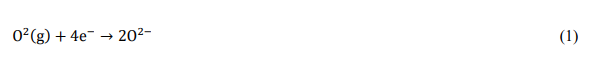
Oxygen anions formed at the cathode migrate through the ionically conductive, solid oxide electrolyte membrane to the anode side as shown by equation (2)

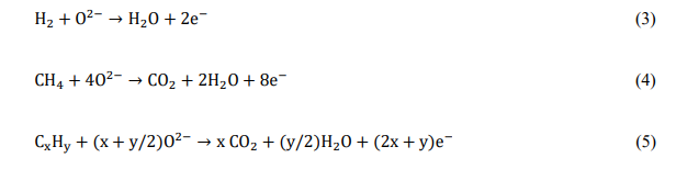
Oxygen anions react with the fuel (e.g., H2, CH4, CxHy etc) fed to the conductive anode and release electrons into the external circuit as shown by equations (3), (4) and (5)
Therefore, if a continuous supply of reactants is maintained at the electrodes, i.e. air at the cathode and fuel at the anode, an SOFC can continuously generate a direct electronic current from the anode to the cathode in the external circuit. This direct current can be used to power an external load connected in circuit.
It is important to note that reactions at fuel cell electrodes can only occur at interfaces or lines of contact where the reactant, electronic conductor and ionically conductive phase all meet. These interfaces are known as three phase boundaries (TPB)[16]. To this end, typical gas-fuelled SOFC electrodes are usually porous composites of the electrolyte material with an active and electronically conductive phase, such as a metal or a conductive mixed-metal oxide. For the cathode reaction to occur, oxygen from air needs to be present at the line of contact between the suspended electronically conductive phase and its containing porous electrolytic scaffold (which serves as an extension of the electrolyte) in order to gain electrons from the external circuit and be transported into the dense electrolyte. For the anode fuel oxidation reaction to occur, the fuel needs to be present at the interface between the electronically and ionically conductive phases where it can react with the oxygen anions from the dense electrolyte and simultaneously release electrons. The anode reaction mechanism for a SOFC fuelled with H2 is shown in Fig. 2.
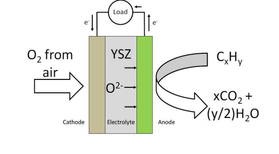
Figure 1. Operating schematic of a solid oxide fuel cell.
Since O2- ions are the charge carriers, SOFCs have the inherent advantage of better fuel flexibility than most other types of fuel cells, because they can utilize any combustible fuel. This encompasses a wide variety of fuels like H2, CO, gaseous and liquid hydrocarbons and, in principle, SOFCs can even operate on solid carbonaceous fuels such as, coal and renewable biomass [5][12][17][18][19][20][21][22][23][24][25][26]. SOFCs also have a higher tolerance for fuel impurities than other types of fuel cells like, PEMFCs and AFCs[5][12][18].
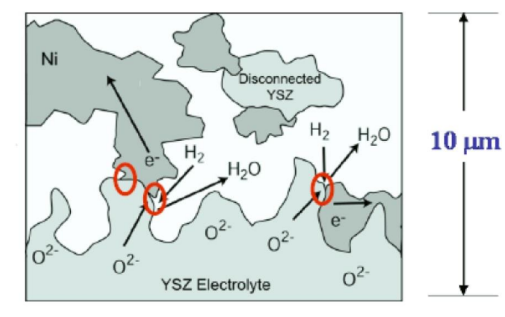
Figure 2. Anode reaction mechanism for a H2- fuelled SOFC (Three Phase Boundary concept) [17]
2.2. Molten carbonate fuel cells
Molten carbonate fuel cells (MCFC) are based on molten carbonate salt mixtures as electrolytes, which conduct carbonate anions at high temperatures. The molten salts are usually held in an inert solid ceramic porous matrix, such as beta-alumina or zirconia, via surface tension. The electrolytes are typically composed of a mixture of Li2CO3, K2CO3 and Na2CO3 salts and can be either binary eutectic mixtures containing (Li, K)2CO3 or (Li, Na)2CO3 or ternary eutectic mixtures of (Li, K, Na)2CO3. Based on the need to maintain the carbonate mixture in molten form, the operating temperatures for these fuel cells range from 873 K to 1073 K. The molten electrolyte separates the air (oxidant) and recycled CO2 on the cathode side from the fuel (reductant) on the anode side as shown in Fig. 3. These fuel cells generate electricity by electrochemically combining the oxygen from air on the cathode side with the fuel on the anode side through the ionically conductive electrolyte as follows:
Oxygen from air and recycled CO2 from the anode chamber react with the conductive cathode to produce carbonate anions by gaining electrons from the external circuit as shown by equation (6)
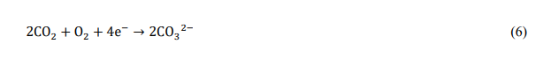
Carbonate anions formed at the cathode migrate through the ionically conductive, molten electrolyte-containing ceramic matrix to the anode side as shown by equation (7)

Carbonate anions react with fuel (e.g. H2, CH4, CxHy etc) fed to the conductive anode and release electrons into the external circuit as shown by equations (8), (9) and (10). CO2 from the reaction products is then recycled back to the cathode.
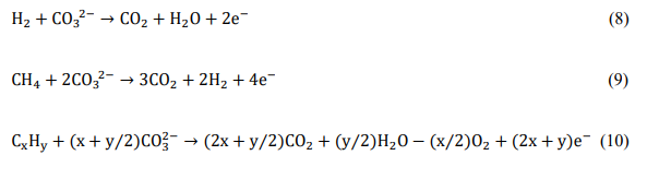
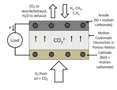
Figure 3. Operating schematic of a molten carbonate fuel cell.
In MCFCs, three phase boundaries are achieved by the use of electrodes that consist of a porous conductive or metallic scaffold with the molten carbonate maintained in it by surface tension[27]. The electrode reactions occur when the gaseous reactants come into contact with the interfacial regions between the metallic scaffold and the ionically conductive molten carbonate phase.
The key aspect of MCFCs is that they essentially operate by the transfer of O2- ions as charge carriers, in the form of carbonates. Therefore, like SOFCS, MCFCs also have the fuel flexibility for being able to utilize any type of combustible fuel and, in principle, can also operate on solid carbonaceous fuels like coal and biomass.
3. Performance characterization techniques for fuel cells
The operating properties of a fuel cell and the factors governing its performance output can be characterized through V-i polarization curves and impedance spectroscopy. These techniques are useful in determining the cell characteristics that limit performance and can provide clues for improving the design of cell components.
3.1. V-i polarization curves
V-i polarization curves are basically voltage-current response plots for fuel cells. These curves are generated by ramping through the applied voltages across the cell and plotting them against the corresponding currents drawn from the fuel cell. A sample V-i curve is shown in Fig. 4. The voltage at which the current drawn is zero is called the Open Circuit Voltage (OCV). For electrolytes that are pure ion conductors, this voltage is the potential associated with the anode oxidation reaction and is directly related to its free energy by the Nernst Equation (equation (11.))

where T is the cell operating temperature, 'n' is the number of moles of electrons released
in the oxidation reaction, and 'F' is the Faraday constant.
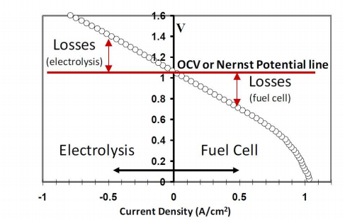
Figure 4. Sample V-i polarization curve.
Since a real fuel cell has resistance losses, varying the voltage will cause the V-i curve to deviate from the Nernst Potential. For positive currents, the cell is said to be in "fuel cell mode" and the cell potential is below the Nernst Potential. The spontaneous anode oxidation reaction is then used to drive electrons in the external circuit, to cause oxygen dissociation at the cathode, and to transport oxygen anions to the anode for further fuel oxidation. At negative currents, the cell operation is in "electrolysis mode". In this mode, the excess countervoltage (above OCV) is used to dissociate the oxidized fuel, for example H2O, forming the fuel (H2), while the oxygen anions are then transported through the electrolyte to produce oxygen gas at the electrode exposed to air. The slope of the V-i curve gives the overall cell resistance at each point,
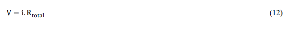
Rtotal consists of the losses from the electrolyte and each of the electrodes. The electrolyte loss is simply the resistance associated with the transfer of O2- ions through the electrolyte and depends on the thickness and conductivity of the electrolyte material used. The electrode losses are the kinetic losses associated with the ease of the reactions occurring at the cathode and the anode. However, it is not possible to separate Rtotal into each of its constituent losses only by using V-i curves. Impedance spectroscopy is a technique used for this purpose, as described in the next sub-section.
A corresponding power density curve can also be plotted for a V-i curve by calculating the product of the voltage and the corresponding current at each point of the V-i curve (equation 13). As a practice, current values are always normalized to the effective or working area of the electrolyte to give area specific values.

3.2. Electrochemical impedance spectroscopy
The contributions of each of the cell components towards the overall cell resistance (Rtotal) are obtained by impedance spectroscopy. This technique is used to measure the impedance of the fuel cell over a range of frequencies, and therefore its frequency response. A Nyquist impedance plot is one way to represent the data obtained by impedance spectroscopy. A sample Nyquist plot for a fuel cell is shown in Fig. 5. These are plots of the imaginary parts of the cell impedance against its real parts at each of the frequencies. These plots are obtained galvanostatically (at a fixed current) by performing a frequency sweep (from to 0 Hz) on an applied a.c. perturbation to the fuel cell current.
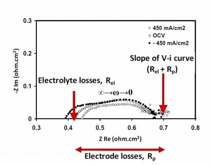
Figure 5. Sample Nyquist plot.
At high frequencies, the capacitive components (terms related to the ease of electrode reactions) go to zero, so that the high frequency intercept of the Nyquist plot with the abscissa gives the purely resistive component, or the ohmic resistance, of the cell impedance. This term is mostly due to the resistance offered by the electrolyte to oxygen ion transfer (Rel). At very low frequencies, the capacitive components also start behaving like resistors. The length of the line segment underneath the Nyquist curve, between the high and low frequency intercepts with the abscissa, gives the polarization resistance (Rp) or the non-ohmic resistance.
Together, Rel and Rp give the total resistance associated with the flow of a d.c. current (zero frequency) through the fuel cell. That is,
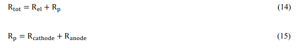
Rel is related to the conductivity and the thickness of the electrolyte used, while Rp is the sum of the non-ohmic resistances due to the cathode and anode reactions (equation 15).
4. Direct carbon fuel cells
A direct carbon fuel cell (DCFC) is a fuel cell that uses a solid, carbon-rich material as the fuel. The cell produces energy by electrochemically combining carbon and oxygen, releasing carbon dioxide as a by-product. The overall reaction of a DCFC is shown in equation (16)

This reaction proceeds via mechanisms that vary with cell design and the type of electrolyte used. The majority of the DCFC technologies being developed at present are based on MCFC or SOFC. In a direct-carbon MCFC, the carbon oxidation reaction at the anode side proceeds by reaction of the solid fuel with carbonate anions (equation 17). Carbonates are good oxidizing agents but electronic insulators, so that the performance of these cells is usually limited by electron transfer to the external circuit.

In the case of direct-carbon SOFCS, the overall anode reaction is that of the carbon being oxidized by oxygen anions from the solid oxide electrolyte (equation 18). However, direct contact between the solid fuel and the solid electrolyte is inefficient.
Various anode designs have been employed in order to make contact between the fuel and the oxygen ions from the solid electrolyte. Typically, this occurs through intermediate steps, making the anode reaction mechanisms more involved, as will be discussed in the next section.

The total efficiency of a DCFC is a product of several factors. Three of the most important are the thermodynamic (theoretical) efficiency of the overall process, the fuel utilization fraction (the fraction of the fuel that is converted electrochemically), and the operating efficiency of the cell. The thermodynamic efficiency, for any fuel cell, including DCFC, is given by the ratio between the free energy ( △G) and the enthalpy ( △H) of the carbon oxidation reaction (equation 16). The thermodynamic efficiency is basically the fraction of the total chemical energy stored in the carbon fuel that can be effectively converted into electrical work. It can be written as,

Since,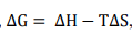 where T = absolute temperature (K) and Entropy change,

The entropy change for the carbon oxidation is a small decrease△s>0 , while △H<0
This gives a ratio greater than 1. Therefore, for a DCFC, it is possible to convert all of the chemical energy in the carbon fuel into electrical energy when an external source of heat is provided.
Fuel utilization efficiency is defined as the fraction of the fuel that converts to electrical energy once it enters the fuel cell. When pure hydrogen is used as a fuel in high temperature fuel cells, the presence of steam as a reaction product dilutes the remaining hydrogen (decreases its chemical potential), thereby reducing its ability to produce electrical energy. A typical maximum fuel utilization is 90%, after which the fuel is too dilute to be useful in the fuel cell. In the case of DCFCs, it may be possible to convert all of the solid carbon fuel into electrical energy because the reaction product, CO2, is in a separate gas phase and at a constant pressure. Therefore, the presence of CO2 will not diminish the chemical potential of the solid carbon allowing the possibility of 100% fuel conversion. In practice, 100% fuel utilization may not be possible because, depending on cell design, there could be some energy penalties associated with ensuring that the carbon fuel remains in contact with the electrode interface. Moreover, at high temperatures (> 1123 K) some of the carbon may be converted mostly to CO.
The Nernst potential of carbon oxidation is ~1 V. An ideal DCFC would be able to operate at this voltage no matter how much current is being drawn and operate at 100% voltage efficiency. In practical use, all fuel cells have kinetic and resistive losses and have to operate at a voltage which is a trade-off between fuel cell efficiency and cost. For example, if the voltage efficiency were to be increased by decreasing the current density, the active area would need to be increased to obtain the necessary power, which in turn would increase capital costs.
5. Approaches in DCFC technology based on SOFCs and MCFCs
With fuel cell electrolytes and their respective air-contacting cathodes being well- studied and considered as standard, the main challenge in making a practical DCFC involves the design of an anode system that efficiently contacts the carbon fuel with the oxidizing species from the electrolyte. This will help minimize cell performance losses and make the high-level of efficiencies, theoretically achievable by DCFCs possible.
There are various approaches that are being developed for this purpose.
5.1. Direct carbon-molten carbonate fuel cell
This type of DCFC is based on a conventional MCFC with the ions migrating from the cathode towards the anode. At MCFC operating temperatures, carbon can be oxidized to CO2 via the cathode and anode reactions shown in Equations (6) and (18) respectively. Since molten carbonates are good oxidizers but poor electronic conductors, the main factor limiting performance in direct carbon-MCFCs is the slow anode kinetics associated with the limited TPB caused by the lack of contact of the fuel with an electronic conductor.
The operating schematic of a typical direct carbon-molten carbonate fuel cell is shown in Fig. 6 and is similar to that used by N. Cherepy et al[28]. In this system, the anode consists of a porous Ni scaffold containing the molten carbonate mixture. The fuel consists of a conductive form of carbon present at a high enough concentration in a slurry with the molten carbonate as the carrier. This configuration helps the electrochemical reaction also occurring out of direct electrical contact with the metallic current collector, since the conductivity of the carbon also facilitates current collection.
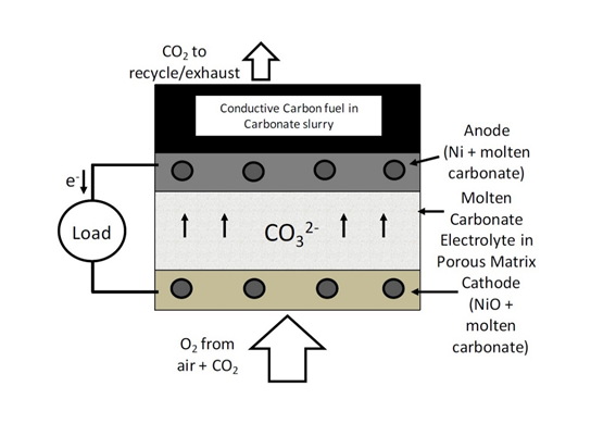
Figure 6. Operating schematic of a direct carbon-MCFC.
Since the carbon fuel is directly oxidized by the carbonate anions, the open circuit potential for these DCFCs is ~ 1 V, the same as that of the carbon oxidation reaction (equation 16). The best possible performance levels in these DCFCs have been observed only when conductive carbons are used as fuels. However, not all forms of carbon are conductive and one of the main drawbacks of DCFCs based on MCFCs is their reduced fuel flexibility.
Moreover, it has been found that the reactivity of the carbon used, i.e. low crystallinity, presence of surface reactive sites, small particle size and high surface area, is also related to the performance of these DCFCs[28][29]. Conductive carbons are not the most reactive forms of carbon and their poor reactivity will always contribute to the anode polarization losses. Therefore, the ideal fuel required by these DCFCs is a form of carbon fuel with sufficient electronic conductivity and chemical reactivity to minimize performance losses due to the anode reaction[28].
Apart from the issues associated with sluggish anode kinetics and high costs associated with producing carbon in a suitable form, DCFCs based on molten carbonates also have problems due to ash build-up in the electrolyte and poor durability due to the highly corrosive nature of the molten carbonate mixture causing damage to other cell components[30]. Therefore, these DCFCs require a lot more development in order to be made practical.
5.2. Direct carbon-solid oxide fuel cells
Using conventional SOFC cathode and electrolyte materials, there are currently three major types of anode technologies being developed to enable the utilization of solid carbonaceous fuels in SOFCs.
5.3. Gasification-driven direct carbon-SOFCs
These DCFCs are similar to conventional gas-fuelled SOFCs. The cell components used in gasification-driven direct carbon SOFCs are the same as in conventional SOFCs and the composite anode consists of the porous ceramic scaffold containing an electronically conductive and catalytic material as shown in Fig. 7. The conventional Ni-YSZ (yttria-stabilized zirconia) cermet is the common anode used in gasification-driven direct carbon-SOFCs.
In these fuel cells being developed by Gur et al [31], oxygen anions from the electrolyte react with CO in the porous anode to form CO2 and release electrons (equation 21). A fraction of the CO2 is then recycled and passed through a bed of carbon particles to form CO by the reverse Boudouard reaction (equation 22). The CO produced from the Boudouard gasifier is then cycled to the anode for oxidation.
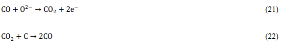
The main issue with this shuttling mechanism is that the reverse Boudouard reaction is an endothermic reaction and is kinetically very slow. This reaction needs very high temperatures to occur and a considerable amount of heat is required to maintain the temperature of the gasifier[32]. Therefore, low fuel consumption along with high heat demands drastically brings down the efficiencies of these fuel cells.
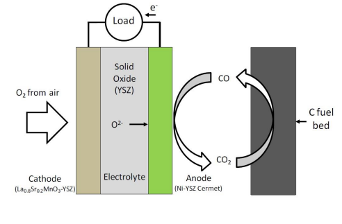
Figure 7. Operating schematic of a gasification-driven direct carbon-SOFC.
5.2.2. Direct carbon-SOFCs with molten carbonate anodes
This technology is a "hybrid" of the key elements of both direct carbon- MCFC and direct carbon-SOFC designs. Essentially, both electrolytes from the MCFC and SOFC are used within one cell with the fuel dispersed within the molten carbonate electrolyte. The physical cell resembles a typical SOFC cell with the molten carbonate residing in the anode chamber as shown in Fig. 8.
These DCFCs are also called Hybrid direct carbon fuel cells (HDCFC) and were conceived by the scientists at SRI International[33]. This "hybrid" concept helps alleviate some issues associated with the standalone versions of the direct carbon-MCFC and SOFC. In the hybrid fuel cell, the cathode is separated from the molten carbonate by the SOFC electrolyte, thus reducing the possibility of cathode corrosion as observed in direct carbon MCFCs[34][35]. It also negates the need to recycle CO2 because the SOFC cathode can operate directly on air. However, the primary motivation for incorporating the molten carbonate in the SOFC anode chamber is for it to serve as an ionically conductive anode for the SOFC electrolyte. This will allow the oxygen to directly contact the carbon fuel and facilitate its oxidation. In HDCFCs, oxygen anions from the SOFC electrolyte contact the carbon particles via the molten carbonate anode to produce a mixture of CO and CO2 in the manner similar to a direct carbon-MCFC [35].
 Figure 8. Operating schematic of a direct carbon-SOFC with a molten carbonate anode.
Nevertheless, molten carbonates lack electronic conductivity and the performance of these cells that still remains is limited due a lack of TPB as in the case of the direct carbon MCFC. Performances can be somewhat improved by introducing an electronically conductive, high surface area metallic mesh for current collection with a reactive form of carbon fuel[36] or by using a conductive form carbon fuel in the molten carbonate anode[37]. Optimal performance can only be achieved if the conductive fuel is always present in the anode at a high enough concentration and if it has a morphology that allows for intimate physical contact with the current collector. Therefore, the incorporation of an electronic conductor is always going to be a performance limiting factor for these fuel cells, requiring an optimal preparation of the fuel-carbonate mixture[23] and adversely affecting their fuel flexibility. Also, etching of the electrolyte[38] and corrosion of the current collectors on the anode side can be problems for cell durability.
5.2.3. Direct carbon-SOFCs with molten metal anodes
The use of a molten metal as an anode for SOFCs was pioneered by Tao et al. at CellTech Power[39]. A very clear advantage of this technology is that the entire anode will be electronically conductive. Moreover, metals are known to react with oxygen to form oxides and have certain amounts of oxygen solubility; therefore, metals could serve as oxygen-transport media as well. The appropriate choice of metal could be very promising in that the entire anode would be active for fuel oxidation, given the high electronic conductivity of all metals and the possibility for good oxygen transport in some.
In choosing a molten metal for operation at 1273 K, Tao et al. considered the following metals based on their melting temperatures: Al, Ga, Ge, In, Sn, Sb, Tl, Pb, Bi, Po, Ag, Hg and Cd. This group then considered the possibility that the metals could be reduced under typical anode conditions by examining the of reduction for the respective metal oxides. For example, Al and Ga were eliminated from consideration because they form very stable oxides that cannot be reduced by carbon. Ge and In were less desirable because their OCV was too close to that of carbon making them poor fuel oxidation catalysts. Cd, Sb, Pb, Po, Tl, Bi and Hg were ruled out because their volatility was too high at 1273 K. This left Sn and Ag as the two remaining anode choices. Based on the work done by CellTech Power, as discussed next, it is still unclear why Ag was eliminated as an anode choice despite its higher oxygen solubility. However, Ag has a positive for oxidation at 1273 K and will not form an oxide. The reason for choosing Sn is probably its higher OCV. This will allow oxygen transport to occur in the form of tin dioxide (SnO2) at a higher potential when the metal is saturated with dissolved oxygen at high currents[40].
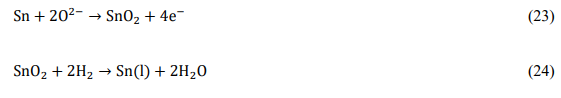
Most of the work done by CellTech Power using their molten Sn anode SOFC concept has been focused only on operation with H2 and JP-8 (jet fuel) as the fuels at 1273 K[39][41][42]. In these experiments, a thin layer (300-500 µm) of molten Sn was held in contact with an SOFC electrolyte using a porous ceramic separator as shown in Fig. 9. Surface tension prevents molten Sn from entering the porous ceramic, so that gaseous fuel (H2 or gaseous pyrolysis products of JP-8) and gaseous oxidation products (H2O and CO) can make contact with the Sn surface. The OCV for Sn oxidation (equation 23) is 0.78 V, which is lower than the oxidation potentials for H2 and other hydrocarbons at 1273 K[43]. Therefore SnO2 formed can be readily reduced by H2 (equation 24) and other carbonaceous fuels.
The operation of this system was suggested to rely on the diffusivity of the dissolved oxygen from the electrolyte in the molten tin (equation 25) and the diffusivity of the gaseous fuel into the molten tin for the fuel oxidation to occur (equation 26)[18][39].
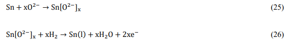
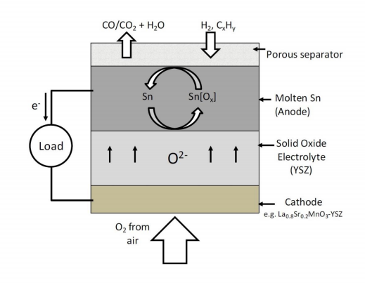
Figure 9. Operating schematic of CellTech Power's molten Sn anode-SOFC.
In these fuel cells, H2 fuel from the feed stream diffuses through the porous separator into the molten tin where it is oxidized by the dissolved oxygen (equation 26). The liquid JP-8 fuel was directly injected into the hot zone of the anode chamber and underwent pyrolysis. The pyrolysis products, consisting of a mixture of various gaseous hydrocarbon components, then diffuse through the porous separator and contact the molten tin to get oxidized by the dissolved oxygen. However, the effect of formation of pyrolysis soot which would clog the porous separator and cause cell failure was not clearly discussed. The performance levels observed with H2 as the fuel were significantly higher than those observed with JP-8. This was because a small molecule like H2 would have a much higher diffusivity in the molten tin compared to the much larger hydrocarbon molecules formed in the case of JP-8. Therefore, for JP-8 the anode polarization losses would be much higher, resulting in lower power levels.
At high temperatures like 1273 K, the diffusivities of the fuel and oxygen in tin still might not have high enough values, even for H2, and their contributions to the ohmic and anode polarization losses can be significant. Given that the electrolyte and cathode losses for an SOFC at 1273 K are nearly zero, the poor performances observed in these experiments prove that almost all of the losses are due to the sluggish oxygen transport in the molten Sn anode[43].
From the work done by CellTech Power, it was clear that molten Sn did not provide an efficient anode mechanism for fuel oxidation. However, the factors limiting the performance of these electrodes and the properties of SnO2 to serve as the oxygen carrying medium to the fuel still needed to be studied. Moreover, the operating temperature used in this study was too high and could compromise cell component stability in conventional SOFCs. With the advancement in cell fabrication techniques, new catalytic materials for the cathode and the use of thin electrolytes, the typical [16] operating temperature for a SOFC can be as low as 973 K[16]. Studying further the practicality of Sn as an anode at these lower temperatures would actually determine if it could be a realistic solution.
Due to the inherent benefits of having a molten metal anode based direct carbon SOFC, a further investigation of the oxygen transport properties of molten Sn and other molten metal anode candidates was warranted in order to understand their suitability for oxidizing solid carbon and be suitable as molten metal anodes for advanced direct carbon fuel cells.
6. Conclusions
Fuel cell systems[44] based on the type of DCFC described in this topic review would be highly fuel flexible, tolerant of typical fuel impurities and could provide a high efficiency means of electricity generation from both coal and biomass while simultaneously allowing for easy CO2 capture.
References
- Sequeira, C.A.C. High Temperature Corrosion: Fundamentals and Engineering. John Wiley & Sons, Ltd., Hoboken, New Jersey, USA, 2019.
- Energy Efficiency: A Recipe for Success. World Energy Council, London, UK, 2010.
- Ptasinski, K.J., Thermodynamic efficiency of biomass gasification and biofuels conversion. Biofuels Bioproducts & Biorefining - Biofpr 2008, 2: 239-253.
- Levine, J.S.; Cofer, W. R.; Cahoon D. R.; Winstead, E. L., Biomass Burning - a Driver for Global Change. Environ. Sci Tech., 1995, 29: A120-A125
- Singhal, S.C., High Temperature Solid Oxide Fuel Cells: Fundamentals, Design and Applications, Elsevier, Oxford, UK, 2003.
- Cao, D.X.; Sun, Y.; Wang, G.L., Direct carbon fuel cell. Fundamentals and recent developments. J. Power Sources 2007, 167: 250-257.
- Program on Technology Innovation : Systems Assessment of Direct Carbon Fuel Cells Technology; Electric Power Research Institute, Palo Alto, CA, USA, 2008.
- Kurzweil, P., History - Fuel Cells, Elsevier, Amsterdam, The Netherlands, 2009.
- Goret, J.; Trémillon, B., Propriétés chimiques et électrochimiques en solution dans les hydroxydes alcalins fondus-IV, Comportement électrochimique de quelques metaux utilisés comme electrodes indicatrices. Electrochim. Acta 1967, 12: 1065-1083.
- Dicks, A.L., The role of carbon in fuel cells J. Power Sources 2006, 156:128-141.
- Cropper, N. A. J.; Geiger, S.; Jollie, D. M.; Fuel cells; a survey of current developments. J. Power Sources 2004, 131:57-61.
- O' Hayre, R. P.; Cha, S.W.; Collela, W.; Prinz, F. B.; Fuel Cell Fundamentals, John Wiley & Sons, Ltd., Hoboken, New Jersey, USA, 2009, p. xxii, 409 p.
- Brito, P.S.D.; Sequeira, C.A.C., Army's future needs for batteries and fuel cells. Sci & Technol. Materials 1996, 8:13-15.
- Shobha, T., Mayanna, S. M.; Sequeira, C.A.C., Preparation and characterization of Co-W alloys, as anode materials for methanol fuel cells. J. Power Sources 2002, 108:261-264.
- Yamahara, K.; Jacobson, C.P.; Visco, S. J.; DeJonghe, L.C., Inpluence of powders on polycrystalline zirconias. Proc. 8th Symp. Solid Oxide Fuel Cells (SOFC -VIII) 2003, 187 - 195.
- Vohs, J.M.; Gorte, R.J., High-performance SOFC cathodes prepared by infiltration. Adv. Mater. 2009, 21:943-956
- McIntosh, S.; Gorte, R. J., Direct hydrocarbon solid oxide fuel cells. Chem. Rev. 2004, 104: 4845 - 4865.
- Minh, N. G.; Takahashi, T., Science and Technology of Ceramic Fuel Cells. Elsevier, Amsterdam, The Netherlands, 1995
- Bove, R.; Lunghi, P. Electric power generation from landfill gas using traditional and innovative technologies. Energy Conv. Mgmt. 2006, 47:1391-1401.
- Pusz, J.; Bove, R.; Sammes, N.M., Landfill gas energy recovery based on microtubular solid oxide fuel cells. Proc. 9th Symp. Solid Oxide Fuel Cells (SOFC-IX) 2005, 277.
- Park, S. D.; Vohs, J. M.; Gorte, R.J., Direct oxidation of hydrocarbons in a solid oxide fuel cell. Nature 2000, 404 (6775): 265-267.
- Kim, H.; Park, S.; Vohs, J. M.; Gorte, R. J., Direct oxidation of liquid fuels in a solid oxide fuel cell. J. Electrochem. Soc. 2001, 148: A693-A695.
- Jain, S.L.; Lakeman, J. B.; Pointon, K.D.; Marshall, R.; Irvine, J.T.S., Electrochemical performance of a hybrid direct carbon fuel cell powered by pyrolysed MDF. Energy Environ. Sci. 2009, 2:687-693.
- Abernatthy, H.; Gemmen, R.; Gerdes, K.; Koslowske, M.; Tao, T., Basic properties of a liquid tin anode solid oxide fuel cell J. Power Sources, 2011, 196: 4564-4572.
- Lee, A. G.; Li, S.; Mitchell, R. E.; Gür, T.M., Conversion of solid carbonaceous fuels in a fluidized bed fuel cell. Electrochemical and Solid-State Letters, 2008, 11: B20-B23.
- Venâncio, S. A.; V. de Miranda, P.E., Direct utilization of carbonaceous fuels in multifunctional SOFC anodes for the electrosynthesis of chemicals or the generation of electricity. Int. J. Hydrogen Energy 2017, 42: 13927-13938.
- Dicks, A.L., Molten carbonate fuel cells. Current opinion in Solid State & Materials Science 2004, 8; 379-383.
- Cherepy, N. J.; Krueger, R.; Fiet, K. J.; Jankowski, A.F.; Cooper, J. F., Direct conversion of carbon fuels in a molten carbonate fuel cell. J. Electrochem. Soc. 2005, 152: A80-A87.
- Cooper, J.F., In Direct conversion of coal and coal-derived carbon in fuel cells. 2nd Int. Conf. Fuel Cell Science, Engineering and Technology, ASME, Rochester, New York, USA, 2004; 2004.
- Selman, J. R., Molten-salt fuel cells Technical and economic challenges. J. Power Sources 2006, 160:852-857.
- Gür, T.M; Huggins, R.A., Direct electrochemical conversion of carbon to electrical energy in a high-temperature fuel cell. J. Electrochem. Soc. 1992, 139: L95-L97.
- Gür, T.M.; Homel, M., Virkar, A.V., High performance solid oxide fuel cell operating on dry gasified coal. J. Power Sources 2010, 195: 1085-1090.
- Heydorn, B.; Crouch-Baker, S., Direct carbon conversions: Progressions of Power. Fuel Cell Rev., IOP, New York, USA, 2006.
- Nabae, Y.; Pointon, K. D.; Irvine, J.T.S., Electrochemical oxidation of solid carbon in hydric DCFC with solid oxide and, molten carbonate binary electrolyte. Energy Environ. Sci. 2008, 1: 148–155.
- Jiang, C. R.; Irvine, J.T.S., Catalysis and oxidation of carbon in a hybrid direct carbon fuel cell. J. Power Sources 2011, 196: 7318-7322.
- Nabae, Y.; Pointon, K. D.; Irvine, J.T.S., Ni/C slurries based on molten carbonates as a fuel for hybrid direct carbon fuel cells. J. Electrochem. Soc. 2009, 156: B716-B720.
- Lilipin, A.S.; Balachov, I. I.; Dubois, L. H.; Sanjurjo, A.; McKubre, M.C., Liquid anode electrochemical cell. U.S. Patent 2006/0019 132, 2006.
- Jiang, C. R.; Ma, J.J.; Bonaccorso, A. D.; Irvine, J.T.S., Demonstration of high power, direct conversion of waste-derived carbon in a hybrid direct carbon fuel cell. Energy Environ. Sci. 2012, 5: 6973-6980.
- Tao, T.; Bateman, L.; Bentley, J.; Slaney, M., Liquid tin anode solid oxide fuel cell for direct carbonaceous fuel conversion. ECS Trans. 2007, 5:463-472.
- Tao, T.; White, R.; Klotz, S., Liquid metal anode for JP-8 fuel cell. In DTIC Document, 2009:11-63.
- Tao, T.; Slaney, M.; Bateman, L.; Bentley, J., Anode polarization in liquid tin anode solid oxide fuel cell. ECS Trans. 2007, 7:1389-1397.
- McPhee, W.A.G.; Bateman, L.; Koslowske, M.; Slaney, M.; Uzep, Z.; Bentley, J.; Tao, T., Direct JP-8 conversion using a liquid tin anode solid oxide fuel cell (LTA-SOFC) for military applications. J. Fuel Cell Science and Technology, 2011, 8,(4).
- Koslowske, M. T.; McPhee, W.A.; Bateman, L.S.; Slaney, M. J.; Bentley, J.; Tao, T., Advanced cell development for increased direct JP-8 performance in the liquid tin anode SOFC. Ceramic Engineering and Science Proceedings (American Ceramic Society), 2009, 30:27-35.
- Kacprzak, A.; Wlodarczyk, R., Materials selection and construction development for ensuring the availability and durability of the molten hydroxide electrolyte direct carbon fuel cell (MH-MCFC). Materials 2020, 13(20), 4659.