Plastic production has been rapidly growing across the world and, at the end of their use, many of the plastic products become waste disposed of in landfills or dispersed, causing serious environmental and health issues. From a sustainability point of view, the conversion of plastic waste to fuels or, better yet, to individual monomers, leads to a much greener waste management compared to landfill disposal.
- pyrolysis
- plastic waste
- carbon nanotubes
- plastic oil
- fuels
- monomer recovery
- olefins
1. Introduction
Plastic products play a critical role in our lives and are being used in large quantities due to their durability, versatility, light weight, and low cost [1][2]. The increase in the world population and subsequent living standards have caused a rapid increase in municipal solid waste generation of to up to 1.3 billion tons per annum [3]. Reportedly, plastic waste is the third largest contributor of municipal solid waste [4].
In addition to landfilling, there are four distinctive approaches for plastic waste management. Primary mechanical recycling is a technique in which single-type uncontaminated and clean plastic wastes are reprocessed, resulting in a product without changing the basic structure and equivalent quality. Although this method is cost-effective, washing the waste materials generates a new waste stream and, more importantly, plastic wastes usually consist of mixtures of different plastics, often arranged as composites with other materials and are either difficult or impossible to recycle. Secondary recycling is another mechanical recycling approach that follows a decontamination process, remelting, remolding and re-extruding. Size reduction, contaminants removal, separation from other waste materials, make this approach less favorable in terms of operating cost. Tertiary recycling is a chemical or/and thermochemical recycling, which includes chemolysis/solvolysis (i.e., glycolysis, hydrolysis, methanolysis, and alcoholysis), gasification, partial oxidation, and pyrolysis. In this approach, large polymer molecules of plastic wastes are converted into shorter molecules through the use of heat and/or chemical reactions. This technique produces fuels or value-added chemicals that are useful for the synthesis of new plastics and other products. Quaternary recycling is waste combustion (incineration) of the waste material for energy recovery. It seems to be the simplest method; however, it generates pollution and may not meet the circular economy milestones [5][6].
2. Plastic Waste Properties
To achieve a very good heat/mass transfer during the pyrolysis process, plastic wastes are typically crushed, shredded and sieved to obtain small size flakes, i.e., less than 2 mm. Proximate and ultimate analysis of different plastic wastes are presented in Table 1 and Table 2. A high volatile matter content (above 90 wt.%) along with a high carbon and hydrogen content make plastic waste an excellent candidate for the pyrolysis process, leading to a high conversion to the liquid/gas products.
| Plastic Types | Carbon | Hydrogen | Oxygen | Nitrogen | Sulfur |
|---|---|---|---|---|---|
| HDPE | 78 | 13 | 4 | 0.06 | 0.08 |
| PP | 84 | 14 | 1 | 0.02 | 0.08 |
| PS | 90 | 9 | 1 | 0.07 | 0.08 |
| PET | 77 | 13 | 5 | 0.20 | NA |
| Plastic Types | Moisture Content | Fixed Carbon | Volatile Matters | Ash Content | HHV (MJ/Kg) |
|---|---|---|---|---|---|
| HDPE | 0.0 | 0.3 | 99.8 | 1.4 | 49.4 |
| LDPE | 0.3 | 0.0 | 99.7 | 0.4 | 46.4 |
| PP | 0.2 | 1.2 | 97.8 | 1.9 | 46.4 |
| PS | 0.3 | 0.2 | 99.6 | 0.0 | 41.9 |
| PET | 0.5 | 7.8 | 91.8 | 0.1 | 30.2 |
3. Pyrolysis Process
Pyrolysis is a versatile thermal cracking process that occurs in the absence of oxygen at temperatures above 400 °C. Typically, pyrolysis processes are classified as slow, fast, and flash [8][9]. This thermochemical process breaks down the long chain polymer molecules into smaller and less complex molecules through heat and chemical reactions. Slow pyrolysis is typically performed at temperatures between 350 and 550 °C, with 1 to 10 °C/min heating rates, and a prolonged vapor residence time. The major product of slow pyrolysis is a solid residue, called char, as a slow heating rate favors solid formation among various parallel-competitive reactions [9]. Fast pyrolysis often takes place at temperatures between 500 and 700 °C. The heating rate experienced by the feedstock is above 1000 °C/min, and vapor residence times are normally in the range of a few seconds [10]. Fast pyrolysis favors liquid production and, depending on the feedstock type, the liquid yield can surprisingly reach up to 90 wt.% for the pyrolysis of polyolefin materials [11]. In flash pyrolysis, the temperature is usually above 700 °C, the heating rate experienced by the feed is extremely fast, and vapor residence times are in the range of milliseconds [9]. Flash pyrolysis can produce higher yields of oil than fast pyrolysis for biomass feedstocks, while it differs for plastic waste, as the latter produces more gas compared to other products [12]. The products obtained from the pyrolysis of plastic wastes (all types, alone, or as mixtures) are categorized into liquid/wax, solid residues, and gas [13].
Pyrolysis is a robust technique and can be used for either fuel or monomer recovery, particularly while addressing plastic waste management challenges. For example, liquid pyrolysis oil obtained from fast pyrolysis is an excellent source of gasoline and diesel [13]. Unlike water-rich pyrolysis bio-based oils derived from biomass feedstocks, the plastic oils have a high heating value, almost three times more than bio-oils, and similar to diesel fuels, due to absence of highly oxygenated compounds and water [14]. The acid content of plastic oils also is dramatically lower than that of bio-oils and, therefore, no further upgrading may be required for fuel applications. The pyrolysis coproducts include solid (char), which can be used as an adsorbent [15][16][17], and gas, a valuable resource that can be used as an energy supplier for the pyrolysis process.
The produced plastic oil can be a liquid or a wax. The wax is yellowish with a high viscosity at room temperature and is predominantly composed of alkanes and alkenes hydrocarbons with a high boiling point (C20+) [18]. Wax is typically an intermediate product, and a further process, such as fluid catalytic cracking (FCC), is required to convert it into liquid fuels. Liquid plastic oil is comprised of mainly aliphatic compounds as well as mono- and polyaromatics [13]. In addition to being a promising precursor for fuel applications, the plastic oil can be used as an intermediate and converted into ethylene and propylene through further cracking at higher temperatures and extremely low contact times. The major gaseous species forming the “gas product” are methane, ethylene, ethane, propylene, butadiene, and butane [19]. The gas product can be used as an energy source to provide the required pyrolysis energy, making the process self-sustaining and independent from external energy sources. In addition, the valuable olefin components present in the gas stream can be separated and recovered for chemical recycling. The solid residue is the remaining pyrolysis product, mostly made of coke and ash [20].
4. Plastic Oil Cracking
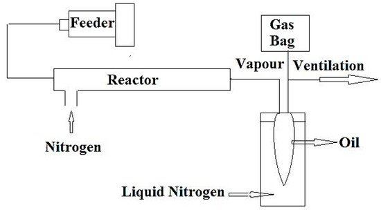
A schematic diagram of the pyrolysis oil cracking set-up is shown in Figure 1.

Figure 1. Schematic diagram of the experimental apparatus for cracking of raw plastic pyrolysis oil and extracted oil after separation of aromatics (adapted from Reference [19]).
5. Upgrading of Pyrolysis Plastic Oils
5.1. Blending
A blend of conventional fuel and plastic oil can be a potential solution. The fuel trials using blends in conventional engines reveal a stable performance with less emission of NOx and SOx compared to diesel and gasoline fuels [21].
5.2. Hydrogenation
A combination of hydrogenating and blending have been suggested to upgrade the plastic oil quality in order to meet the EN590 standard [22]. The fuel properties of plastic oil, diesel, and hydrogenated plastic oil along with the EN590 standard are compared in Table 3.
| Properties | Lower Limit Standards EN590 | Upper Limit Standards EN590 | Diesel | Plastic Pyrolysis Oil | Hydrogenated Plastic Pyrolysis Oil |
|---|---|---|---|---|---|
| Density (kg/m3) | 820 | 840 | 837 | 771 | 851 |
| Pour Point (°C) | - | - | −15 | −30 | −20 |
| Flash Point (°C) | 55 | - | 72 | 20 | 65 |
| Fire Point (°C) | - | - | 82 | 30 | 72 |
| Calculated Cetane Index | 46 | - | 52 | 60 | 62 |
| Kinematic Viscosity (mm2/s) | 2 | 4.5 | 2.31 | 1.78 | 3.5 |
| Gross Calorific Value (MJ/kg) | - | - | 46 | 45 | 45 |
| Ash Content (wt.%) | - | 0.1 | 0.01 | 0.01 | 0.01 |
| Conradson Carbon Residue (wt.%) |
5.3. Liquid-Liquid Extraction
The high aromatic content of plastic oils, particularly those obtained from pyrolysis of mixed plastics containing polystyrene, leads to a decrease in the engine performance and an increase in emissions due to a long ignition delay [23]. Generally, the low cetane number fuels, caused by high aromatic content, are not suitable for conventional diesel engines as they can cause unstable combustion. As such, the aromatic compounds can be separated and removed via solvent extraction prior to the utilization of plastic oil in diesel engines.
6. Carbon Nanotubes
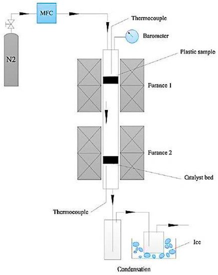
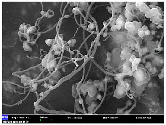
Recently, the potential fabrication of CNTs from the pyrolysis of plastic waste has drawn researchers’ attentions, adding a significant value to the plastic wastes. The process of converting plastic waste into CNTs is composed of two successive stages (Figure 2). In the first stage, the plastic waste is converted to the volatile vapor in the absence of oxygen and at a moderate temperature (approximately 550 °C). Then, the produced vapor is introduced into the second stage at a high pressure of 1 MPa and a temperature of 750 °C in the presence of Ni-based catalyst where it is converted into CNTs on the surface of the catalyst through the chemical vapor deposition mechanism. In this advanced process, CNT yields can reach up to 25 wt.% [24]. In the second stage, during pyrolysis at 750 °C, plastic waste vapors further decompose to the mixtures of their monomers (e.g., ethylene, propylene, and styrene). These light gases serve as carbon donors for CNTs formation. Moreover, the produced vapors from the first stage contain a significant amount of hydrogen, which plays an undeniable role in the formation of CNTs. Hydrogen moderates the rate of carbon deposition and prevents catalyst deactivation and poisoning by continuous surface cleansing of the catalyst surfaces [25][26][27][28]. A SEM image of CNT growth on Ni-based catalyst is shown in Figure 3.

Figure 2. Schematic diagram of two-stage pyrolysis reactor system (adapted from [24]).

Figure 3. CNT growth on Ni-based catalyst (adapted from [24]).
This entry is adapted from the peer-reviewed paper 10.3390/ma14102586
References
- Aguado, J.; Serrano, D.; Miguel, G.S.; Castro, M.; Madrid, S. Feedstock Recycling of Polyethylene in a Two-Step Thermo-Catalytic Reaction System. J. Anal. Appl. Pyrolysis 2007, 79, 415–423.
- Al-Salem, S.M.; Antelava, A.; Constantinou, A.; Manos, G.; Dutta, A. A review on thermal and catalytic pyrolysis of plastic solid waste (PSW). J. Environ. Manag. 2017, 197, 177–198.
- Kunwar, B.; Cheng, H.; Chandrashekaran, S.R.; Sharma, B.K. Plastics to Fuel: A Review. Renew. Sustain. Energy Rev. 2016, 54, 421–428.
- Kumar, S.; Panda, A.K.; Singh, R. A Review on Tertiary Recycling of High-Density Polyethylene to Fuel. Resour. Conserv. Recycl. 2011, 55, 893–910.
- Singh, A.; Sharma, T.C.; Kishore, P. Thermal Degradation Kinetics and Reaction Models of 1,3,5-Triamino-2,4,6-Trinitrobenzene-Based Plastic-Bonded Explosives Containing Fluoropolymer Matrices. J. Therm. Anal. Calorim. 2017, 129, 1403–1414.
- Achilias, D.; Roupakias, C.; Megalokonomos, P.; Lappas, A.; Antonakou, Ε. Chemical Recycling of Plastic Wastes Made from Polyethylene (LDPE and HDPE) and Polypropylene (PP). J. Hazard. Mater. 2007, 149, 536–542.
- Yao, D.; Yang, H.; Chen, H.; Williams, P.T. Co-Precipitation, Impregnation and so-Gel Preparation of Ni Catalysts for Pyrolysis-Catalytic Steam Reforming of Waste Plastics. Appl. Catal. B Environ. 2018, 239, 565–577.
- Papari, S.; Hawboldt, K. A Review on the Pyrolysis of Woody Biomass to Bio-Oil: Focus on Kinetic Models. Renew. Sustain. Energy Rev. 2015, 52, 1580–1595.
- Papari, S.; Hawboldt, K.; Helleur, R. Pyrolysis: A Theoretical and Experimental Study on the Conversion of Softwood Sawmill Residues to Biooil. Ind. Eng. Chem. Res. 2015, 54, 605–611.
- Papari, S.; Hawboldt, K. Development and Validation of a Process Model To Describe Pyrolysis of Forestry Residues in an Auger Reactor. Energy Fuels. 2017, 31, 10833–10841.
- Heydariaraghi, M.; Ghorbanian, S.; Hallajisani, A.; Salehpour, A. Fuel Properties of the Oils Produced from the Pyrolysis of Commonly-Used Polymers: Effect of Fractionating Column. J. Anal. Appl. Pyrolysis 2016, 121, 307–317.
- Lovett, S.; Berruti, F.; Behie, L.A. Ultrapyrolytic Upgrading of Plastic Wastes and Plastics/Heavy Oil Mixtures to Valuable Light Gas Products. Ind. Eng. Chem. Res. 1997, 36, 4436–4444.
- Williams, P.T.; Williams, E.A. Fluidised Bed Pyrolysis of Low Density Polyethylene to Produce Petrochemical Feedstock. J. Anal. Appl. Pyrolysis 1999, 51, 107–126.
- Papari, S.; Hawboldt, K.; Fransham, P. Study of Selective Condensation for Woody Biomass Pyrolysis Oil Vapours. Fuel 2019, 245, 233–239.
- Bamdad, H.; Hawboldt, K. Comparative Study Between Physicochemical Characterization of Biochar and Metal Organic Frameworks (MOFs) As Gas Adsorbents. Can. J. Chem. Eng. 2016, 94, 2114–2120.
- Bamdad, H.; Hawboldt, K.; MacQuarrie, S.; Papari, S. Application of Biochar for Acid Gas Removal: Experimental and Statistical Analysis Using CO2. Environ. Sci. Pollut. Res. 2019, 26, 10902–10915.
- Bamdad, H.; Hawboldt, K.; MacQuarrie, S. A Review on Common Adsorbents for Acid Gases Removal: Focus on Biochar. Renew. Sustain. Energy Rev. 2018, 81, 1705–1720.
- Arabiourrutia, M.; Elordi, G.; Lopez, G.; Borsella, E.; Bilbao, J.; Olazar, M. Characterization of the Waxes Obtained by the Pyrolysis of Polyolefin Plastics in a Conical Spouted Bed Reactor. J. Anal. Appl. Pyrolysis 2012, 94, 230–237.
- Tsuji, T.; Hasegawa, K.; Masuda, T. Thermal Cracking of Oils from Waste Plastics. J. Mater. Cycles Waste Manag. 2003, 5, 102–106.
- Onwudili, J.A.; Insura, N.; Williams, P.T. Composition of Products from the Pyrolysis of Polyethylene and Polystyrene in a Closed Batch Reactor: Effects of Temperature and Residence Time. J. Anal. Appl. Pyrolysis 2009, 86, 293–303.
- Sharuddin, S.D.A.; Abnisa, F.; Daud, W.M.A.W.; Aroua, M.K. A Review on Pyrolysis of Plastic Wastes. Energy Convers. Manag. 2016, 115, 308–326.
- Mangesh, V.; Padmanabhan, S.; Tamizhdurai, P.; Narayanan, S.; Ramesh, A. Combustion and Emission Analysis of Hydrogenated Waste Polypropylene Pyrolysis Oil Blended With Diesel. J. Hazard. Mater. 2020, 386, 121453.
- Chandran, M.; Tamilkolundu, S.; Murugesan, C. Characterization Studies: Waste Plastic Oil and Its Blends. Energy Sources Part A Recover. Util. Environ. Eff. 2019, 42, 281–291.
- Wang, J.; Shen, B.; Lan, M.; Kang, D.; Wu, C. Carbon Nanotubes (CNTs) Production from Catalytic Pyrolysis of Waste Plastics: The Influence of Catalyst and Reaction Pressure. Catal. Today 2020, 351, 50–57.
- Gou, X.; Zhao, D.; Wu, C. Catalytic Conversion of Hard Plastics to Valuable Carbon Nanotubes. J. Anal. Appl. Pyrolysis 2020, 145, 104748.
- Shamsi, R.; Sadeghi, G.M.M.; Vahabi, H.; Seyfi, J.; Sheibani, R.; Zarrintaj, P.; Laoutid, F.; Saeb, M.R. Hopes Beyond PET Recycling: Environmentally Clean and Engineeringly Applicable. J. Polym. Environ. 2019, 27, 2490–2508.
- Moo, J.G.S.; Veksha, A.; Oh, W.-D.; Giannis, A.; Udayanga, W.C.; Lin, S.-X.; Ge, L.; Lisak, G. Plastic Derived Carbon Nanotubes for Electrocatalytic Oxygen Reduction Reaction: Effects of Plastic Feedstock and Synthesis Temperature. Electrochem. Commun. 2019, 101, 11–18.
- Panahi, A.; Wei, Z.; Song, G.; Levendis, Y.A. Influence of Stainless-Steel Catalyst Substrate Type and Pretreatment on Growing Carbon Nanotubes from Waste Postconsumer Plastics. Ind. Eng. Chem. Res. 2019, 58, 3009–3023.
