Your browser does not fully support modern features. Please upgrade for a smoother experience.
Please note this is an old version of this entry, which may differ significantly from the current revision.
Subjects:
Engineering, Electrical & Electronic
Bluetooth 5.1 allows producers to create location applications based on the Angle of Departure (AoD) and the Angle of Arrival (AoA). Accordingly, it is conceivable to design proper Indoor Positioning Systems (IPS), for instance, for the traceability of resources, assets, and people.
- Bluetooth 5.1
- Bluetooth Low Energy
- Bluetooth Direction Finding
- indoor localization
- asset traceability
- Internet of Things
1. Introduction
The specification introduced in [1][2][3] highlights that Bluetooth 5.1 requires modifications to the radio frequency “stack”, i.e., the software protocol. Moreover, also hardware enhancements are expected depending on the chip manufacturer. It is beneficial to heed that, as the main feature, the updated protocol attaches a CTE to every Bluetooth data employed for radiogoniometry. Otherwise, packets remain unchanged to be practiced for conventional BLE transmission [1][2]. The analysis of [1] denotes that CTE is not modulated and transmitted at 250 kHz or, seldom, more than 500 kHz when employing the more effective throughput method of Bluetooth. Its continuance is between 16 and 160 μs. More in detail, as introduced in [1], CTE is composed of an “unwhitened” series of “1” communicated large adequate to permit the receiver to obtain the IQ information without modulation’s influences. As the CTE is transferred at the end, the Cyclic Redundancy Check (CRC) of the packet is not influenced.
Another notable enhancement to the spec [1] greatly simplifies protocol configuration for IQ sampling. This arrangement comprises arranging both the antenna switched and the sample timing, i.e., two fundamental values for the position estimation accuracy. Ordinarily, although several IQ sampling timing arrangements can be practiced, an IQ representation is registered every 1 or 2 μs inside the associate time per antenna. Moreover, the outcomes are reported in the Random Access Memory (RAM) of the BLE SoC. Figure 1 shows how the received signal phase varies as different array antennas sample it.
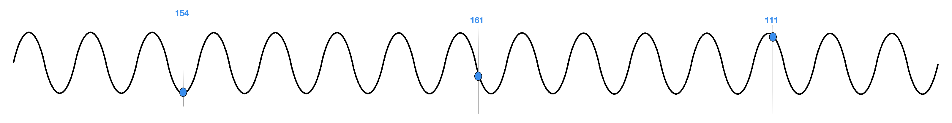 Figure 1. A single transmitter signal shows a different phase when it reaches the antennas at different distances from the source.
Registering IQ samples denotes only the initial action in developing a usage that comprises a location service. Developers must invent or choose the optimal array of antennas for the locators and beacons to accomplish the task. Besides, they must become familiar with the complicated techniques demanded to make radiogoniometry calculations.
As introduced in [1], unique BLE 5.1 packets incorporate a CTE consisting of digital “1 s” to guarantee that the antenna receives a constant frequency for this part of the signal (rather than the changed frequency customarily employed to transmit BLE data). Besides, it is helpful to note that this information string is not “whitened”. Consequently, an adequately developed BLE radio that receives CTE information takes IQ examples throughout the CTE period. More in detail, a unique IQ sample is composed of the signal phase angle and amplitude expressed as cartesian coordinates (Figure 2).
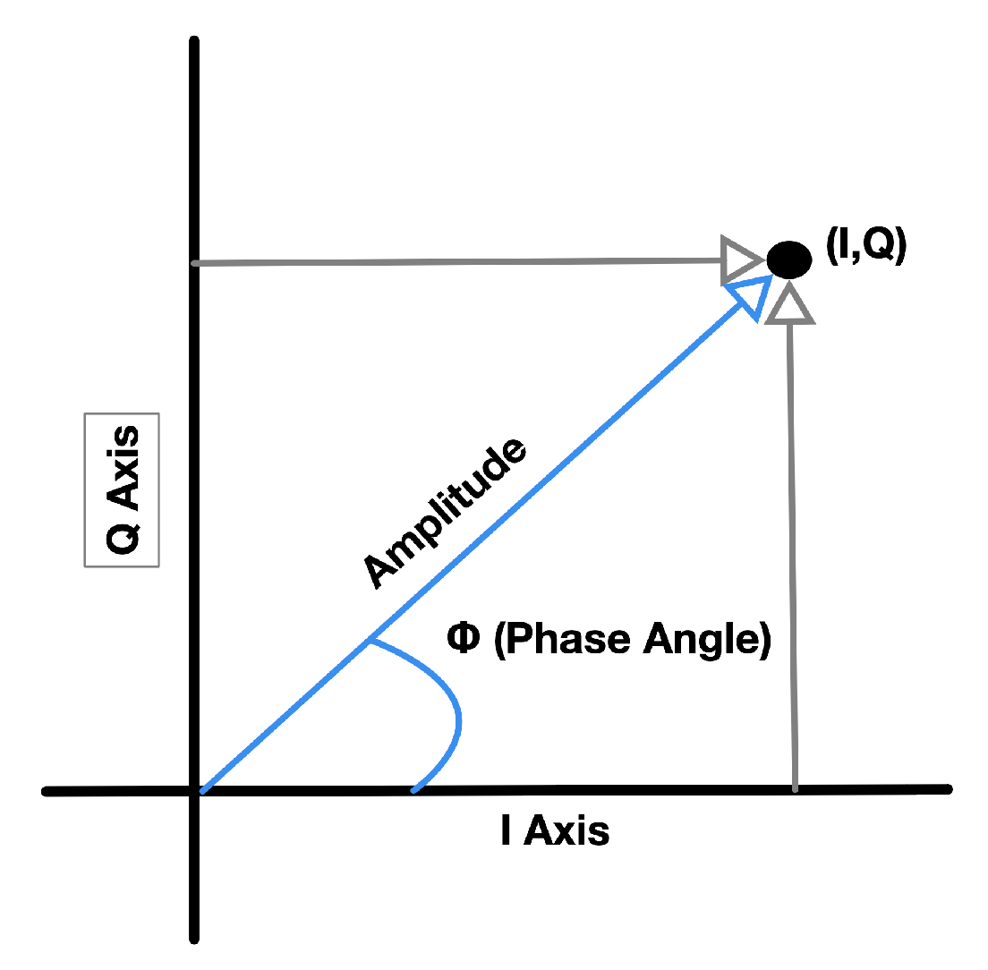 Figure 2. In radiogoniometry applications, the receiving BLE device takes IQ samples of phase angle and amplitude throughout the CTE part of a BLE package for every array’s antenna. Then, this information can be reproduced as cartesian coordinates (I, Q).
Bluetooth Core Specification v5.1 specifies the BLE controller modifications that acknowledge AoD and AoA methods to practice connectionless or connected (“paired”) transmissions [1][2]. Commonly, the AoA technique is employed for connected purposes (for instance, resource traceability), while the AoD technique is practiced with connectionless scenarios, such as IPS. Thus, as clearly described in [1], connected radiogoniometry adopts conventional BLE 5.1 packets, if anything, by introducing CTE at termination. On the other hand, radiogoniometry without connection practices a CTE appended to the periodical Bluetooth advertizing packets (Figure 3). In both scenarios, with and without connection, the maker has to deliver several arrangement actions to start the CTE on the transmitter and the IQ sampling on the receiver. The exact process depends on the choice between AoA or AoD-based applications.
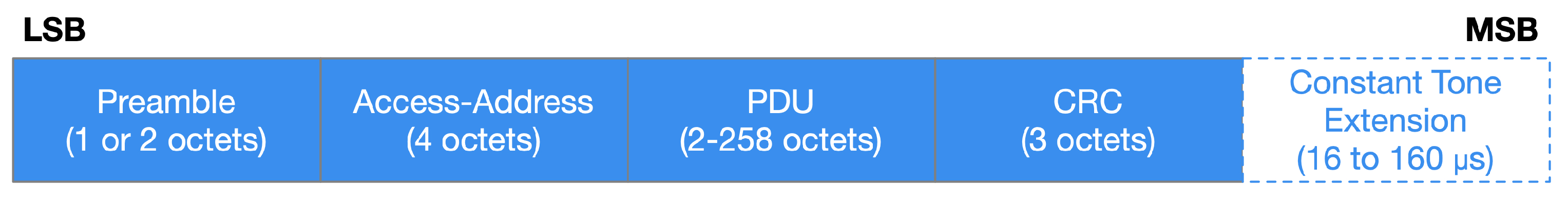 Figure 3. Structure of a Bluetooth 5.1 packet with the duration and position of the CTE. Associated apps add CTE to conventional packets, while those without a connection use an advertizing packet.
2. Practical Use of Bluetooth 5.1
Running radiogoniometry algorithms involves many calculations and requires much RAM and Flash memory. Consequently, all commercial solutions have to consider these requirements. The devices implemented must be suitable for both transmitting and receiving in a Bluetooth radiogoniometry application. Each of them needs to support CTE transmission and acquire IQ samples due to profile-level data guidance that specifies the transmitter antenna layout. In theory, these devices can likewise deliver the complicated computations required to determine the incoming radio signal’s angle of incidence and, from this, the transceiver’s position.
Nordic Semiconductor, Silicon Labs, and Dialog Semiconductor are focusing their architectures on AoD and AoA solutions that broadcast CTE, collect these data and make IQ sampling. Consequently, the maker has to choose which means (i.e., firmware and hardware of the localization engine) will perform the actual radiogoniometry calculations. Nonetheless, things will likely change soon as suppliers release advanced radiogoniometry solutions.
For instance, each company offers development tools that support a tag’s prototyping in an AoA resource tracking scenario. The growing method typically matches that of a typical low-power wireless equipment. Moreover, for testing, a development kit must include an entirely operative serial transceiver built on the BLE 5.1 and other peripherals. The prototyping board can be attached to a computer that entertains a proper Integrated Development Environment (IDE) and the Software Development Kit (SDK) of the chip vendor to enable application development. In this paper, three possible examples of commercial solutions produced by distinct industry leaders have been identified.
Dialog Semiconductor promotes the employment of Bluetooth 5.1 with the development kit DA14695-00HQDEVKT-P-ND [4]. This assortment comprises the main motherboard, an offspring card containing the Bluetooth 5.1 SoC DA14695, and wiring for connection with a computer. Silicon Labs proposes the Wireless Gecko SLWSTK6006A kit [5] that encompasses six daughter cards based on the SoC Bluetooth 5.1 EFR32BG21 that allow the prototyping of a traceability system of resources with multiple tags. Nordic Semiconductor proposes the nRF52840-DK [6] developed with nRF52840 SoC, which is thoroughly agreeable with the SoC Bluetooth 5.1 nRF52811.
A comparison of the previously mentioned prototyping boards is shown in Table 1.
Table 1. Prototyping boards comparison.
| Board | MCU | Memory | Output Power | Protocol Stack | Frequency Band | Interfaces | UI |
|---|---|---|---|---|---|---|---|
| DA14695-00HQDEVKT-P [4] | Cortex-M33F, Cortex-M0+ |
512 kB | 6 dBm | Bluetooth | 2.4 GHz | I/O, USB |
LEDs, LCD Screen |
| SLWSTK6006A [5] | Cortex-M33 | 1024 kB | 10 dBm | Bluetooth | 2.4 GHz | I/O, USB |
Buttons, LEDs, LCD Screen |
| nRF52840 DK [6] | Cortex-M4 | 64 MB | 8 dBm | Bluetooth, Bluetooth Mesh, Thread, ZigBee |
2.4 GHz | I/O, USB |
Buttons, LEDs, |
Bluetooth 5.1 does not broadcast data with CTE, nor does IQ sampling by default. It is up to the developer to set up the architecture to include these characteristics employing specific development instruments. The IDE and SDK concede the Host-Controlled Interface (HCI) management. Consequently, the host can practice it to set up the controller to make the CTE and IQ sampling. It is valuable to remark that, for connectionless situations (i.e., the model commonly practiced by AoD), the device delivers the subsequent startup stages of the controller (Figure 4):
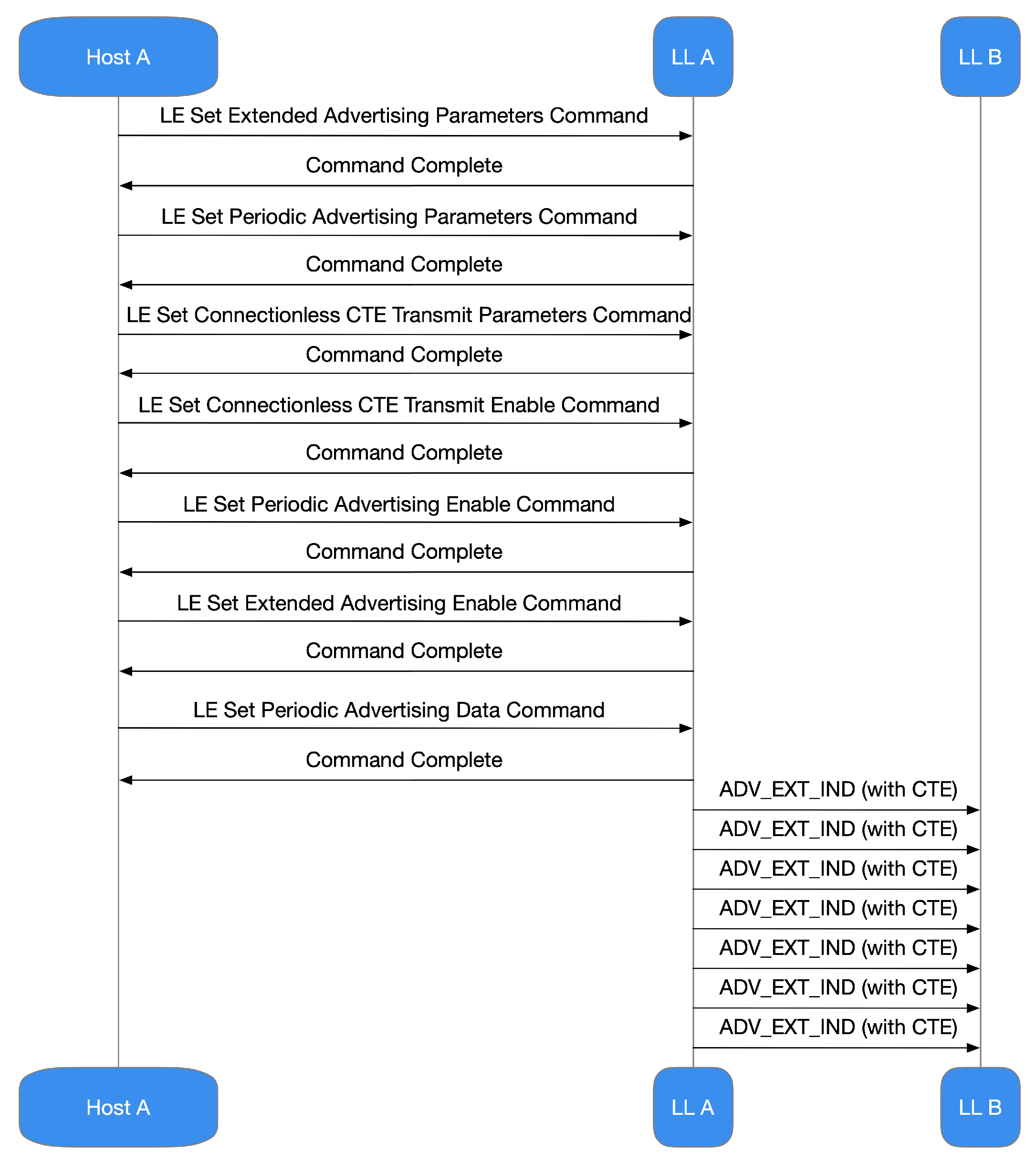 Figure 4. Actions concerning controller start-up delivered by the appliance for connectionless situations, i.e., those commonly practiced by AoD.
-
configuring extended advertizing;
-
configuration of periodic advertizing;
-
configuration of the CTE transmission;
-
enabling CTE advertizing;
-
enabling periodic advertizing;
-
enabling extended advertizing;
-
setting of the advertizing data.
Scanning devices sketched to obtain CTE information and practice IQ samples transferred by the sender must be implemented in the following process:
-
set up the widespread scan
-
begin the widespread scan;
-
synchronize with the collected periodical advertizing packets;
-
let IQ sampling without connection.
In connected situations in which AoA is commonly practiced, both the devices (Master and Slave) expect the other device to transmit CTE data. In these cases, appeals are executed by transmitting a specific CTE Link Layer (LL) package comprising a group of peculiarities that set up the CTE formulation. If the distant device cannot sustain CTE, it will notify the local one, and the latter will not transmit additional CTE calls practicing the connection in progress. More in detail, the device making the request proceeds:
-
through the set up of reception parameters of the CTE in the controller;
-
through the enabling of CTE applications in the controller;
-
through the acquisition and management of IQ statements;
-
through maiming the communication of the CTE request when it is no longer needed.
The responding device proceeds:
-
through the set up of transmission parameters of the CTE in the controller;
-
through the enabling of CTE replies in the controller;
-
through the acquisition and reply to CTE LL inquiries from the other appliance.
In the Bluetooth 5.1 spec [1][2], the HCI includes a novel method, “LE Read Antenna Information”, which enables the device to gather data on the antennas held by its controller. So, it is helpful to perceive that when IQ sampling is achieved through an antenna array, every obtained sample need to be assigned to a definite antenna. Suddenly, the sampling has to be accomplished systematically. Using a model defined in the HCI arrangement rules and compliance with stringent timing commands facilitates this methodical procedure. The process these regulations are exercized and how each device practices them is strictly related to the employment, i.e., if it practices AoD or AoA and if the appliance is broadcasting or gathering. For instance, a transmitting device equipped with a unique antenna transmits consecutive information incorporating CTE. However, IQ sampling is regularly conducted by the acquiring device, regardless of the antennas it uses.
The period designated for CTE management is separated within an opening guard period of 4 μs, a reference period of 8 μs, and then into a series of switch slots, sample slots, or combinations of them (Figure 5). During the reporting period, no antenna switching happens, and eight IQ samples are collected. The device could employ the reference samples to determine the signal frequency and deduce the wavelength, improving the accuracy of the angle calculations.
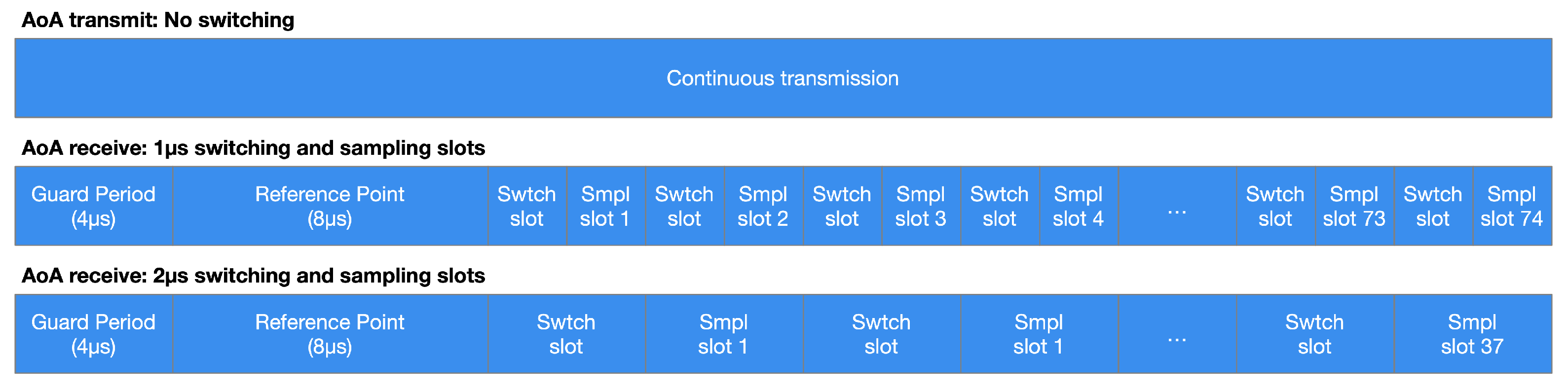 Figure 5. This example represents 1 μs and 2 μs timing switching and sampling in an AoA context. The broadcasting device, equipped with a unique antenna, continuously sends data with CTE while the receiving one performs IQ sampling according to a switching and sampling sequence.
3. Conclusions
The analysis carried out showed that the Core Specification amendment assumed in Bluetooth 5.1 improves IQ information management. The latter can be practiced to support RF radiogoniometry approaches that measure the AoD or AoA of BLE wireless communication and then employ this knowledge to assess a transmitter’s location. Nevertheless, it is essential to remark on two concepts. The techniques can be utilized as a background in working position finding purposes, for instance, IPS and asset tracking, to name a few. However, their correctness can be rigorously related to a well-sketched antenna array, a certified wireless radiogoniometry method, CPU resources, and adequate memory to achieve complicated calculations. Anyhow, the availability of wholesale Bluetooth 5.1 Direction Finding architectures, localization-intended firmware, and antenna arrays could support planners to design employment aiming at localization services with centimeter precision.
An evaluation scenario regarding position finding determinations has been considered in this paper to achieve sub-meter error precision. The obtained results showed that the total average distance error was about 0.7 m, representing a reliable result regarding the sub-meter precision target. The goal of the simple test implemented in this paper was not to achieve an accuracy of the centimeter order, although Bluetooth 5.1 is theoretically able to achieve it, but below 1 m.
It is reasonable to conclude that the enhancements proffered to version 5.1 of the Bluetooth Core Specification produce the new information expected by radiogoniometry exercizing IQ sampling and CTE. The spec practices asserted manufacturing methods to ascertain the signal’s path. Moreover, it regulates interfaces, arrangements, and intercommunications. There is an extra benefit ascertained by the evidence that reasonable radiogoniometry is interoperable with all semiconductor vendors, which, in turn, offers application solutions for Bluetooth. Manufactures have been receptive to propose hardware, software, IDEs, and SDKs that permit developers to immediately comprehend how to set up systems that catch the benefit of Bluetooth radiogoniometry. Commercial IPS and radiogoniometry solutions demand considerable expertise, especially in treating firmware and antenna arrays for localization engines. However, future Bluetooth radiogoniometry profiles promise to simplify this challenge further.
This entry is adapted from the peer-reviewed paper 10.3390/s21113589
References
- Bluetooth Special Interest Group (SIG). Bluetooth Core Specification Version 5.1 Feature Overview. 2019. Available online: (accessed on 15 January 2021).
- Bluetooth Special Interest Group (SIG). Bluetooth Legacy Specification. 2019. Available online: (accessed on 15 January 2021).
- Bluetooth Special Interest Group (SIG). Bluetooth 5.1 Direction Finding. 2019. Available online: (accessed on 15 January 2021).
- Dialog Semiconductor. SmartBondTM DA1469x Product Family. 2019. Available online: (accessed on 15 January 2021).
- Silicon Labs. UG427: EFR32xG21 2.4 GHz 20 dBm Wireless Starter Kit User’s Guide. 2020. Available online: (accessed on 15 January 2021).
- Nordic Semiconductor. Bluetooth Low Energy, Bluetooth Mesh, NFC, Thread and Zigbee Development Kit for the nRF52840 SoC. 2020. Available online: (accessed on 15 January 2021).
This entry is offline, you can click here to edit this entry!