1. Background
Concerns regarding fossil fuel stockpiling and strict legislation against contaminated emissions from internal combustion engines have forced engine designers and manufacturers to continuously pursue improved engine performance and emission characteristics. Extensive research has been conducted to simultaneously improve engine efficiency and reduce emission levels through the application of new technologies, such as engine reduction, new combustion concepts, alternative and/or renewable energy sources, turbocharging, and improved fuel-air mixing. To meet the above-mentioned demands, natural gas has been adopted as an alternative fuel because it is suitable for use in internal combustion engines and has widespread global reserves and acceptable emission behavior. Gas engines are becoming increasingly attractive in applications such as industrial prime mounds, transportation, and stationary power. Further research is also being conducted to improve gas engine performance and emission characteristics and overcome deficiencies in various load plans to become feasible alternatives for various applications. Kalam et al. [
3] have previously compared natural gas and gasoline performance in engines. To evaluate the output and emission levels, a bifuel spark ignition (SI) multicylinder engine operated under several partial and full-load test conditions was investigated for either gasoline or natural gas. Results show that while natural gas produced 15–20% less power than gasoline, the brake-specific fuel consumption (BSFC) was lower by 18%. At the same output power, natural gas produced fewer emissions, except for NOx. Klimkiewicz and Teodorczyk [
4] investigated direct injection SI engines to improve gas engine performance. A series of frame sealer photographs related to injection and combustion processes was obtained along with the in-cylinder pressure profile. The effect of the spark plug location on gas engine performance was shown to be lower than that of conventional engines. The dual gas injection fuel delivery system also improved engine performance by providing a more stable gas–air mixing ignition function in the combustion chamber. Evans et al. [
5] made another comparison of gasoline and natural gas combustion for single-cylinder engines. The authors showed that while much lower emissions could be achieved by natural gas, the brake average effective pressure (BMEP) of natural gas fuel engines was ~12% lower at any ignition timing. As a result, at full load, the gas engine produced ~50% less total hydrocarbons (THCs) and carbon monoxide (CO) than the gasoline engine. When an engine is designed as a dedicated natural gas engine, some parts and systems must be redesigned to provide optimal performance compared to conventional engines. This includes modifications of compression ratios, spark plugs, cooling and lubrication systems, charging entertainment, and gas exchange processes to meet the thermal fluid design criteria. One of the most important considerations for an internal combustion engine is the design of an appropriate camshaft profile. Proper valve timing is required, as the combustion chamber must have the appropriate trapped air:fuel ratio, while the optimum pumping loss and overlapping pumping loss must be achieved simultaneously.
The Miller cycle [
6] was initially proposed to improve engine efficiency. This cycle is an over-expanded cycle, i.e., one with a higher expansion ratio than compression ratio. It has recently been proposed as a means of reducing hazardous emissions while maintaining engine efficiency by lowering the engine compression rates and maximizing the gas temperature and pressure in cylinders.
Many reports have described the concept of the Miller cycle engine and investigated various aspects of the Miller cycle engine design and operation. Alsargh et al. [
7] and Zhao and Chen [
8] conducted theoretical investigations on Miller cycle engine performance and studied the effects of key engine design variables and system inversibility. Endo et al. [
9] have described the design of a large commercial (280–1100 kW) gas engine using the Miller cycle principle, claiming a fuel economy advantage of >5% over existing technologies of its class. Gheorghiu and Uberschör [
10] studied overextended engines for use in hybrid vehicles and investigated the causes of efficiency loss in common implementations of these cycles. Wang and Lucston [
11] and Wang et al. [
12] investigated the application of the Miller cycle concept to reduce engine emissions and found that a significant reduction in engine fuel consumption was possible, despite its penalties.
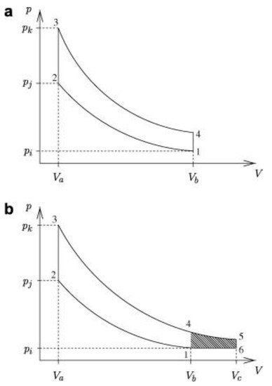
shows the air-standard auto and Miller cycles and the additional work that can be extracted from the Miller cycle (shaded). Heywood [
13] showed that it is possible to achieve significant increases in engine efficiency in excessively extended cycles, especially at low compression rates.
Figure 1. Comparison of Otto and Miller air-standard cycles. (a) Air-standard Otto cycle; (b) Air-standard Miller cycle.
The Miller cycle is a modification of the overinflation cycle, which provides a higher expansion ratio than the compression ratio with improved thermal efficiency compared to the conventional internal combustion engine operating conditions [
14]. In practice, this difference in expansion ratio can be achieved through a compression stroke that includes a late or early closing of the intake valve. This effectively reduces the compression stroke, but maintains the combustion and expansion processes as normal to extract additional energy before the exhaust process while reducing the brake average effective pressure (BMEP) to improve thermal efficiency [
14,
15]. The brake mean effective pressure metric is used to define the operation of the actual engine output defined in the brake output. To avoid a short compression stroke, turbochargers or superchargers have been used to maintain a stable BMEP level and thus ensure continued benefits of this cycle [
14]. Therefore, the Miller cycle uses boosting to recover the lost charge caused by a smaller displacement during compression. This cycle also provides cooling to the precombustion fuel–air mixture according to the inlet valve closing timing to help minimize the combustion knock problems with SI engine operation prior to ignition [
15].
Miller [
16] also demonstrated that controlling the paging of the intake valve closure (IVC) and exhaust valve opening (EVO) has a significant impact on engine performance. Similar to the Atkinson cycle [
17], the expansion ratio in the Miller cycle exceeds the compression ratio (). This can be achieved by either late-intake valve closure (LIVC) or early intake valve closure (EIVC), depending on the engine boost pressure and engine speed [
17,
18,
19,
20]. Unlike the Atkinson cycle, however, the Miller cycle can improve engine efficiency without reducing power because of supercharged and turbocharged utilization. In recent years, numerous studies have been conducted to improve engine performance using Miller cycles. Anderson et al. [
21] examined the naturally aspirated Miller cycle SI engine using LIVC based on primary and secondary law analysis. The authors found that the LIVC required less fuel to produce the same output compared to the base engine and showed 6.3% higher thermal efficiency at partial loads. In addition, LIVC had better thermal-mechanical criteria owing to the high inlet manifold pressure. We et al. [
22] simulated Miller cycles to compare them with standard auto cycles based on thermodynamic models. For Miller cycle applications, superchargers have been recommended because the trapped mass is too low without supercharging, even lower than the default Otto cycle. However, no such loss has been shown in other studies of optimal power density properties for the Atkinson, Miller, and dual cycles [
23,
24,
25].
To overcome the disadvantages of exhaust gas recirculation (EGR), Benazes et al. [
26] investigated whether the Atkinson cycle was suitable for lowering the filling temperature in cylinders. This was achieved by advancing the IVC on a medium diesel engine equipped with a fully variable valve drive (VVA) system, maintaining constant inlet and exhaust pressure. The results confirmed that the Atkinson cycles could reduce gas temperature in cylinders along with gas pressure and density during the compression stroke.
Al-Sarki et al. [
18] investigated the relationship between thermal efficiency, compression ratio, and expansion ratio for ideal naturally aspirated (air-standard) Miller cycles using finite-time thermodynamics. This model provides instructions for predicting the performance of the Miller cycle engine when the correct model parameters are used. Martins and Lanzanova [
27] presented a detailed 1D simulation analysis of the Miller cycle SI engine at full load when driving ethanol hydroxide with different supercharges and valve train configurations. In the study, the effects of IVC timing and camshaft profiles, charge dilution through EGR or excessive air on combustion periods, and temperature in the cylinders were investigated. Detailed evaluations of major losses have also been conducted, and several possible arrangements have been studied. When applying the Miller cycle concept, a diesel engine brake efficiency of >40% has been achieved. They [
27] showed that the highest efficiency values were achieved with solenoid-operated valves and initial IVCs. The pumping loss associated with LIVC reduces the appeal of this option. However, the high intake pressure required for very high EIVC cases (>5 bar) makes this option very difficult for current engines. Operation is expected to be practically unachievable at EIVC prior to 460 crank angle (CAD) after ignition TDC.
Gas engine emissions include THCs, CO, CO
2, and NOx, among which NOx are the most harmful to the environment. The Miller cycle engine is one of the most promising ways to reduce these emissions as it has a much lower combustion temperature that reduces NOx formation. An experimental study by Wang et al. [
28] showed that the application of Miller cycles in standard auto-cycles results in a NOx reduction rate of ~8% and a loss of engine power at full load of only 1%. Similar studies on the Miller cycle concept of Wang and Ruxton [
29] showed a significant reduction in NOx.
Konka et al. [
30] conducted performance analysis for output and thermal efficiency. The maximum output and thermal efficiency criteria were investigated for air-standard non-reversible double Miller cycles using LIVC. In this study, optimal engine operation and design parameters were achieved through thermodynamic optimization to maximize the output and thermal efficiency. Furthermore, the application of this method to a single-cylinder, direct injection diesel engine was studied experimentally and theoretically. Two Miller cycle approaches, which provided 5 and 10 CAD-delayed IVCs compared to standard conditions, were applied in conjunction with two different camshafts. The results showed that NO and CO
2 emissions had decreased by 48% and 2.2%, while HC(hydro-carbon) and CO emissions were increased by 46% and 34%, respectively. Further, effective power and efficiency were decreased by 6.4%, and 9.2% respectively. The optimal condition was defined as 10 CAD delay because of maximum NO reduction [
31].
Linaldini et al. [
32] investigated the possibility of reducing soot formation at NOx and partial loads and the limitations thereof by applying a Miller cycle on conventional high-speed diesel engines. Analysis was performed using GT power and Kiva-3V simulation tools for engine analysis and in-cylinder analysis, respectively, showing that combustion was essentially cleaner with a 10% and 50% reduction in NOx and soot formation, respectively. However, these authors focused on the dedicated (pure) gas engine to simplify the fuel supply system and engine operating mode, and to improve the characteristics of emission.