The article presents the concept of Multi-Addressed Fiber Bragg Structures (MAFBS) and their usage in Microwave Photonic Sensor Systems (MPSS). The theory of MAFBS is the logical evolution of the theory of Addressed Fiber Bragg Structures (AFBS), which implement a microwave-photonic tecnique for their interrogation. The MAFBS is a special type of Fiber Bragg Grating (FBG), the reflection spectrum of which has three (or more) narrow notches. The frequencies of narrow notches are located in infrared range of electromagnetic spectrum, while differences between them – in microwave frequency range. All cross-differences between optical frequencies of single MAFBS are called address frequencies set. When the additive optical response from a single MAFBS, passing through optical filter with oblique frequency response, is received by a photodetector, the complex electrical signal, which consists of all cross-frequency beatings of all optical frequencies, is taken at its output. This complex electrical signal at the photodetector’s output contains enough information to determine the central frequency shift of the MAFBS. The work discusses the method of address frequencies analysis with the microwave-photonic measuring conversion, which allows to define the central frequency shift of an MAFBS.
- fiber Bagg grating
- microwave-photonic sensor system
- addressed fiber Bragg structures
- multi-addressed fiber Bragg structures
- fiber-optic sensor
Introduction
Common problems of Fiber Bragg Gratings (FBG) array interrogation in sensor systems are the complexity and the high cost of interrogators due to the technique of interrogation and FBG multiplexing [1][2][3][4][5]. Wavelength[1], time[2], frequency[3], polarizing[4], and spatial[5] division multiplexing requires using complex devices, such as spectrum analyzers, spectrometers with tunable Fabry–Perot interferometers, diffraction gratings, etc. All of them use the technique of optic signal receiving on charge-coupled devices with its further complex analysis. The complexity is also caused by the fact that these sensors are not addressable per se, and therefore, any spectrum overlapping leads to interrogation errors[6][7][8].
In parallel with multiplexing methods and microwave-photonic methods, the optical pulse-coding, phase-coding, low coherent interferometer with the cascaded FBGs methods have been developed. The coding methods allow to recognize two or more FBGs with the same spectral range[9][10][11][12]. Spectral-coding sensors are based on code-multiplexing technology[11][12], where the interrogation is conducted in real time according to autocorrelation between sensor spectra and its code signature. A number of works demonstrated that the spectral-amplitude-coding method with super-structured FBG sensors based on discrete prolate spheroidal sequences can be useful even in the case of their optical ranges overlapping[13][14][15][16].
An easier solution was found in the Addressed Fiber Bragg Structure (AFBS) usage with the microwave photonics interrogation method[17]. An AFBS is a special type of FBG, the reflection spectrum of which has two narrow notches. The light passing through AFBS has two narrow optical frequencies, the difference between which is much less than an optical frequency (THz) and is located in microwave range (GHz). The difference frequency is called the address frequency of an AFBS. The address frequency is invariant to strain or temperature fields; moreover, it is invariant to AFBS central frequency shifting. The AFBS in sensor systems is used both as a two-frequency source (due to the fact that it has two narrow optical frequencies with the difference between them being in the microwave range) and as a sensor of measurement system (due to the fact that its address frequency is invariant to measurable fields) simultaneously. It allows to design a microwave-photonic sensor system based on arrays of AFBSs, on condition that the set of address frequencies in the array is orthogonal[17][18].
Multi-Addressed Fiber Bragg Structure
A multi-addressed fiber Bragg structure (MAFBS) is a special type of FBG, similar to AFBS, the reflection spectrum of which has three (or more) narrow notches. The light, having passed through a MAFBS, has three (or more) narrow optical frequencies, the difference between which is much less than an optical frequency (THz), and it is located in microwave range (GHz). The set of all differential frequencies is called the address frequencies set of a MAFBS. The address frequencies set is invariant to strain or temperature fields, and it is also invariant to central frequency shifting[17][18][19][20]. The MAFBS serves both a multi-frequency source and a sensor of measurement system at the same time. It is necessary to require the additional conditions to use a MAFBS as a sensor in a sensor system, namely: the light only from MAFBS’s narrow band frequencies must trap into the light analysis area for the whole MAFBS central frequency shift range, which corresponds to the measurement range[17][18][19][20].
There are at least two approaches to the MAFBS (as well as AFBS) forming: the first of them is the introduction of phase π‑shifts into the classic FBG periodic structure[21] (Figure 1,a), and the second one is the MAFBS forming as a set of ultra-narrowband FBGs[17] (Figure 1,b).
(a)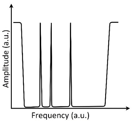
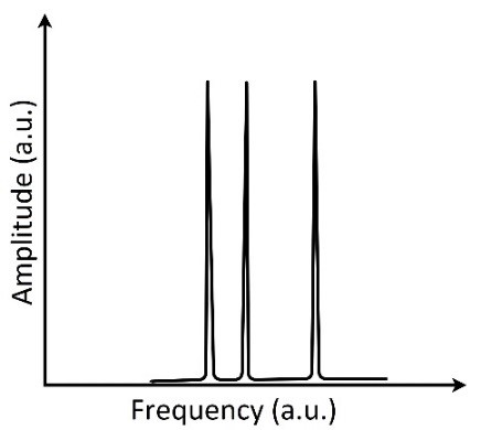
Figure 1. Amplitude-frequency diagrams: (a) transmitted through MAFBS, formed using FBG with π-shifts; (b) reflected from MAFBS, formed as a set of ultra-narrowband FBGs.
MAFBS interrogation principle
Optoelectronic scheme
An example of the optoelectronic scheme for MAFBS interrogation is presented in Figure 2. The optic source – 1 forms finite band light (a), which passes through MAFBS – 2 and forms multi-frequency (in this case three-frequency) signal (c); the three-frequency optic signal, passing through optic filter with oblique amplitude-frequency characteristic – 3, forms asymmetric three-frequency optic signal (d), which is received on a photodetector – 4; after the photodetector, signal is received by an analog-to-digital converter – 5, and its subsequent analysis is performed. The system also includes the reference channel, in which the optic signal is received on a photodetector – 7 directly after the MAFBS without its asymmetrical deformation in the filter, and then the signal is processed using the analog-to-digital converter – 8. All subsequent calculations are carried out with the ratios of values in the measuring and reference channels. It allows to eliminate the influence of light power fluctuation that is not caused by the MAFBS central frequency shifting.
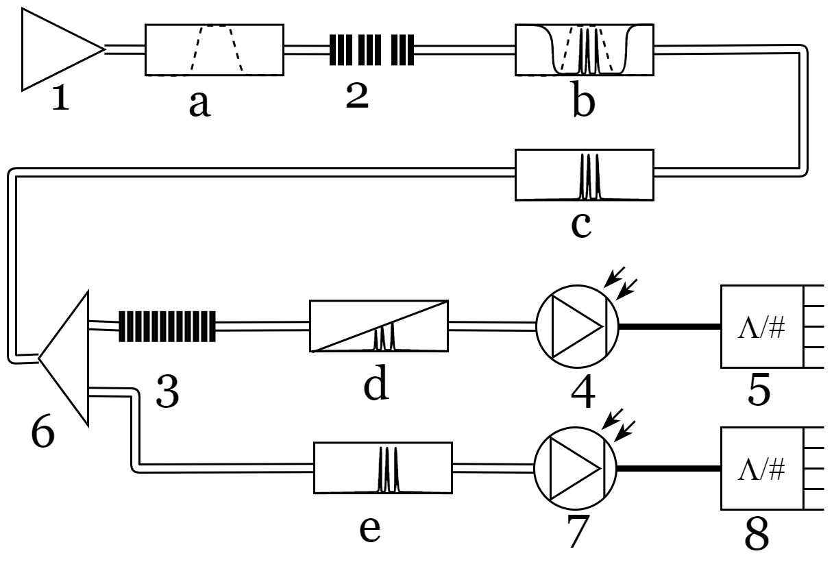
Figure 2. An interrogation scheme of a single MAFBS.
MAFBS spectral response
The shape of a MAFBS spectral response at the output end of the optic filter with oblique amplitude-frequency characteristic is shown in Figure 3, where the following notation is used: ω1, ω2 and ω3 are the frequencies of optical carriers; Ω21 and Ω32 are the address frequencies; k and b are the predefined parameters of the optic filter with an oblique amplitude-frequency characteristic.
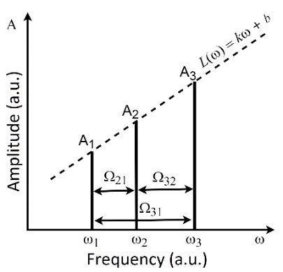
Figure 3. A spectral response of Multi-Addressed Fiber Bragg Structure.
The central frequency shift of the MAFBS leads to a change of the mutual relation of the optical carriers’ amplitudes, which causes a change of the beating parameters at the address frequencies Ω21, Ω32 and their sum Ω31 = Ω21 + Ω32. The task of interrogation is to determine the MAFBS central frequency (or any of the frequencies ω1, ω2, or ω3), using the known parameters of the beating at the address frequencies set.
Mathematical model of MAFBS interrogation
The light response from the MAFBS, which passes through the filter with oblique frequency response, can be written as:

where A1, A2, A3 are the amplitudes, 


in which the oscillations at optical (terahertz) frequencies are excluded[17][18]. The known values in (2) are the address frequencies Ω21, Ω32. The constant signal level in (2), the amplitudes at the address frequencies Ω21, Ω32, and their sum Ω31 give four independent equations for three unknown amplitudes A1, A2 and A3 determination:

where D0, D21, D32 and D31 are the measured values of constant signal level, amplitudes of the address frequencies Ω21, Ω32, and their sum Ω31, respectively.
The resulting system of four equations is overdetermined, since the number of equations exceeds the number of unknowns. Moreover, equations system (3) must be supplemented by the requirements that the points (ω1, A1), (ω2, A2), (ω3, A3) belong to the same line:

Equation (4) describes the filter with an oblique amplitude-frequency characteristic. Moreover, it is necessary to require that the differences ω2 – ω1, ω3 – ω2 are equal to the address frequencies Ω21, Ω32, respectively, and the condition ω3 – ω1 = Ω32 +Ω21 would also be automatically satisfied. Thereby, it is necessary to include the additional relation to the equations system (3):

which binds the task parameters, imposing restrictions of finding a solution, while simultaneously describing the mutual relations between the frequencies. Having the amplitudes A1, A2 and A3 from the equations system (3), supplemented by the relation (5), and using the known values of the parameters k and b of the filter with an oblique linear amplitude-frequency characteristic, one can calculate the MAFBS frequencies ω1, ω2 and ω3.
There are different ways to define the MAFBS central frequency, since MAFBS has three narrow resonances in addition to its main Bragg resonance. We used the definition of the central frequency of MAFBS as an average according to the formula:

which explicitly determines the position of the MAFBS.
The overdetermined equations system can be solved by searching the conditional extremum of the function:

relatively to the restriction:

requiring a minimum of the Lagrange function expressed in the form:

where λ is the Lagrange multiplier.
The expression (9) is equivalent to the requirement that all partial derivatives with respect to the variables A1, A2, A3 and λ are equal to zero, which leads to a set of four nonlinear equations:

where the partial derivatives ∂Φ/∂Ai are not expressed due to their obvious simplicity.
Nonlinear equations system (10) (due to the nonlinearity of the partial derivatives ∂Φ/∂Ai , i = 1, 2, 3) can be solved only numerically. The values A1, A2, A3, which are the solution of the equation system (3) with the exception of the first equation, can be taken as the initial conditions, and λ can be taken as the initial value equal to zero:

After that, the equations system (10), supplemented by the initial values (11), is solved by any well-converging iterative method, for example, the Levenberg-Marquardt[22][23] or Newton-Raphson[24] methods.
The equations system (10) solution gives the values of the amplitudes A1, A2, A3, each of them can be used to determine the MAFBS central frequency position relative to the filter with an oblique amplitude-frequency characteristic. Substituting the found values of the amplitudes A1, A2, A3 in (4), and combining them in (6), we obtain the expression for the central frequency of the MAFBS:

which is a function of the measured values of D0, D21, D32 and D31 – a constant signal level, amplitudes at address frequencies Ω21, Ω32, and their sum Ω31, respectively.
Conclusions
A concept of multi-addressed fiber Bragg structures and mathematical formulation of its interrogation principle is presented. The optoelectronic interrogation system is significantly simplified in comparison with other approaches. The original article includes the simulation results, which clearly demonstrate that the proposed method of the MAFBS central frequency determination is two orders of magnitude more precise than the method based on the generalized modulation factor. It was shown that the suggested method of MAFBS usage in MPSS satisfies accuracy requirements, has potential for further development and allows to move to an experimental research step.
This entry is adapted from the peer-reviewed paper 10.3390/s20092693
References
- R M Measures; S Melle; K Liu; Wavelength demodulated Bragg grating fiber optic sensing systems for addressing smart structure critical issues. Smart Materials and Structures 1992, 1, 36-44, 10.1088/0964-1726/1/1/006.
- Michael A. Davis; David G. Bellemore; Alan D. Kersey; Structural strain mapping using a wavelength/time division addressed fiber Bragg grating array. Smart Structures and Materials: Second European Conference 1994, 2361, 342-346, 10.1117/12.184861.
- V.P. Matveenko; Igor Shardakov; A. A. Voronkov; Natalia Kosheleva; D.S. Lobanov; Grigorii Serovaev; E.M. Spaskova; G. S. Shipunov; Measurement of strains by optical fiber Bragg grating sensors embedded into polymer composite material. Structural Control and Health Monitoring 2017, 25, e2118, 10.1002/stc.2118.
- Xueguang Qiao; Zhihua Shao; Weijia Bao; Qiangzhou Rong; Fiber Bragg Grating Sensors for the Oil Industry. Sensors 2017, 17, 429, 10.3390/s17030429.
- Zhen Ma; Xiyuan Chen; Fiber Bragg Gratings Sensors for Aircraft Wing Shape Measurement: Recent Applications and Technical Analysis. Sensors 2018, 19, 55, 10.3390/s19010055.
- Karim, F. . Full Matlab code for synthesis and optimization of Bragg gratings ; Cambridge Scholars Publishing: Newcastle upon Tyne, 2019; pp. 24.
- Gabriel Cormier; Roger Boudreau; Sylvain Thériault; Real-coded genetic algorithm for Bragg grating parameter synthesis. Journal of the Optical Society of America B 2001, 18, 1771, 10.1364/josab.18.001771.
- Kuo Li; Review of the Strain Modulation Methods Used in Fiber Bragg Grating Sensors. Journal of Sensors 2016, 2016, 1-8, 10.1155/2016/1284520.
- K.P. Koo; M. Leblanc; T.E. Tsai; S.T. Vohra; Fiber-chirped grating Fabry-Perot sensor with multiple-wavelength-addressable free-spectral ranges. IEEE Photonics Technology Letters 1998, 10, 1006-1008, 10.1109/68.681299.
- Zou Wei; H. Ghafouri-Shiraz; Hossam M. H. Shalaby; New code families for fiber-Bragg-grating-based spectral-amplitude-coding optical CDMA systems. IEEE Photonics Technology Letters 2001, 13, 890-892, 10.1109/68.935838.
- Kataoka, Nobuyuki; Wada, Naoya; Terada, Yoshihiro; Sakamoto, Akira; Nishiwaki, Kenji; Nishide, Kenji; Phase-shifted superstructured fiber Bragg grating . Fujikura Technical Review 2011, 40, 6 - 11, .
- C. A. Triana; D. Pastor; M. Varon; Optical code division multiplexing in the design of encoded fiber Bragg grating sensors. Optica Pura y Aplicada 2016, 49, 17-28, 10.7149/opa.49.1.17.
- A. Triana; D. Pastor; Interrogation of super-structured FBG sensors based on discrete prolate spheroidal sequences. Optical Sensors 2017 2017, 10231, 102310, 10.1117/12.2267238.
- Ivan B. Djordjevic; Alaa H. Saleh; Franko Kueppers; Design of DPSS based fiber bragg gratings and their application in all-optical encryption, OCDMA, optical steganography, and orthogonal-division multiplexing.. Optics Express 2014, 22, 10882-10897, 10.1364/oe.22.010882.
- Youngbok Kim; Sie-Wook Jeon; Won-Bae Kwon; Chang-Soo Park; A Wide Dynamics and Fast Scan Interrogating Method for a Fiber Bragg Grating Sensor Network Implemented Using Code Division Multiple Access. Sensors 2012, 12, 5888-5895, 10.3390/s120505888.
- Andrés Triana; Daniel Pastor; Margarita Varón; A Code Division Design Strategy for Multiplexing Fiber Bragg Grating Sensing Networks. Sensors 2017, 17, 2508, 10.3390/s17112508.
- Sakhabutdinov A.J. Microwave-Photonic Sensor Systems Based on Address Fiber Bragg Structures and their Application for Solving Practical Problems. D.Sc. Thesis. Kazan: Kazan National Research Technical University named after A.N. Tupolev-KAI Publ., 2018. (in Russian)
- O.G. Morozov; A. Zh. Sakhabutdinov; Addressed fiber Bragg structures in quasi-distributed microwave-photonic sensor systems. Computer Optics 2019, 43, 535-543, 10.18287/2412-6179-2019-43-4-535-543.
- O G Morozov; A Zh Sakhabutdinov; I I Nureev; R Sh Misbakhov; Modelling and record technologies of address fibre Bragg structures based on two identical ultra-narrow gratings with different central wavelengths. Journal of Physics: Conference Series 2019, 1368, 022049, 10.1088/1742-6596/1368/2/022049.
- O G Morozov; Airat Zhavdatovich Sakhabutdinov; I I Nureev; R Sh Misbakhov; Modelling and record technologies of address fiber Bragg structures based on gratings with two symmetrical pi-phase shifts. Journal of Physics: Conference Series 2019, 1368, 022048, 10.1088/1742-6596/1368/2/022048.
- Novikova V.A., Konnov K.A., Gribaev A.I., Vargel S.V. The Method of Forming a Fiber Bragg Grating with a Phase Shift. Patent RF, no. 2676191, 24.01.2018 (in Russ.)
- Kenneth Levenberg; A method for the solution of certain non-linear problems in least squares. Quarterly of Applied Mathematics 1944, 2, 164-168, 10.1090/qam/10666.
- Donald W. Marquardt; An Algorithm for Least-Squares Estimation of Nonlinear Parameters. Journal of the Society for Industrial and Applied Mathematics 1963, 11, 431-441, 10.1137/0111030.
- Tjalling J. Ypma; Historical Development of the Newton–Raphson Method. SIAM Review 1995, 37, 531-551, 10.1137/1037125.