Electrowetting display (EWD) has promising prospects in the electronic paper industry due to it having superior characteristics, such as the ability to provide a comfortable reading experience and quick response.
- electrowetting display
- technical developments
- dielectric breakdown
- bi-stable
- optical stability
1. Introduction
Electrowetting is the phenomenon of modulating surface wettability via an external electric field, which has drawn great attention in lab-on-a-chip microfluidics [1]. Electrowetting display (EWD) uses electrowetting to control the state of oil inks and display desired images, which has been at the center of attention since 2003, when Hayes and Feenstra reported on the possibilities contained in the system [2]. The road since then has been long and arduous. A plethora of challenges have required solving one by one. Research was later focused on the prediction of the working principle, dielectric material preparation, pixel structure design, electric signal modulation and color panel realization in order to achieve market applications and mass production.
In display theory, the basic principle of electrowetting has been demonstrated to apply in confined pixels. The surface wettability change between the hydrophobic (oleophilic) state and hydrophilic (oleophobic) state causes a switch between the “on” and “off” status in each pixel unit. Tang et al. [3] illuminated the mechanism of oil film opening and predicted the threshold voltage based on the electro-capillary instability of the oil–water interface in the pixel. Zhou et al. [4] formulated a theoretical model of dynamic electrowetting display to predict the opening rate of oil film.
Researchers have also dedicated efforts to the development of robust dielectric materials, as the deterioration of the dielectric layer will directly lead to the failure of the display device and greatly reduce the service time. The current preparation of dielectric layers is a lengthy and error-prone process which includes sample cleaning, film coating, surface treatment and photolithographic patterning [5]. Chen et al. [6] reported the advantages of screen printing techniques for preparing uniform and compact dielectric materials as compared with the conventional spin coating process. Guo et al. [7] selectively injected a fluoropolymer to form hydrophobic patterns based on a combined approach of inkjet printing and phase change filling. In this way, changes to the material properties during the surface treatment of reactive ion etching were avoided. These technical developments enabled the fast preparation of uniform and compatible multi-layer dielectrics.
A well-designed shape and structure of pixel guide the flows of oil inks in the confined system which resolve display defects. Early studies mainly focused on the planar surfaces by varying the shape and size of the pixel to restrict the fluid flow in the display unit [8]. Various shapes of the pixel, including quadrilateral, rectangle, triangle and trapezoid shapes were designed and the response rates and brightness of the images produced were compared. The quadrilateral pixel has a better response rate and brightness, but the improvement is still limited. Additionally, the planar surface still relies on the electric signal, while displaying images in case of backflows [9]. For a limited pixel size and spacing, overflows of the oil inks [10] to the adjacent pixels may take place. Three-dimensional structures reserve excess oil inks and prevent oil backflows and overflows, while the bi-stable features only require electric energy during image conversion, thus, enabling them to be used for a longer time [11]. In addition, “symmetry breaking structure” [12] on the original planar surface realizes the breaking of the oil film under a low voltage and ensures the oil ink flows in a uniform direction.
For application of the electric signal, a proper driving waveform can not only achieve a good optical performance, but also improves the stability of the gray level [13]. The display performance refers to the image quality (e.g., reflectivity, brightness, resolution). Optical stability means that the generated picture will not fluctuate in a certain period of time. The optical performance and stability of EWD are mainly dependent on the electro-fluidic behaviors of oil inks in the pixel. Generally, a higher opening rate and larger aperture ratio are achieved by a larger driving voltage. However, a large voltage may cause oil splitting [14][15]. Conversely, lower voltages can ensure more stable oil ink flows and prevent the breakdown of the dielectric layer. Therefore, the selection of electric voltage requires a tradeoff between performance and stability. A proper electric driving scheme can achieve both expectations in the real operation. By using frequency-and-amplitude modulation and converting a constant voltage to several segments, Yi et al. [16] achieved both high levels of brightness and optical stability and also improved the response speed of oil inks.
Current challenges for electrowetting displays are mainly related to dielectric deterioration, display defects, energy consumption in mono-stable states and color panel realization. In the following sections, the electrowetting principles in the confined configuration will be introduced. The failure mode of the dielectric layer will be analyzed in more details. Suitable pixel structures and driving schemes will be discussed to achieve high performance, optical stability and energy saving displays. Lastly, the latest status and highlights of R&D will be elaborated on in this article, providing the latest insights in the behavior of oil films in pixels, and the creation of colorful images.
2. Principles: Electrowetting in Confined Systems
Electrowetting produces its active influence by changing surface wettability using an external electric field. This effect can be used to control the contact angle of the electrolyte on a solid surface, which was first described in Young–Lippmann’s equation [17].
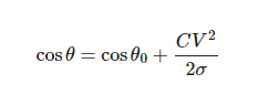
where θ0 is the initial contact angle, θ is the contact angle after applying electrowetting. C (= ε0εr/d) is the capacitance. ε0 is the vacuum permittivity. εr and d are the relative permittivity and thickness of the dielectric layer, respectively. σ is the interfacial tension between the liquid and vapor and V is the applied voltage. For a large capacitance material, the contact angle can be greatly reduced via a relatively small voltage, which results in a surface wettability change from hydrophobic (oleophilic) to hydrophilic (oleophobic).
In electrowetting displays, two types of fluid exist in the confined unit; electrically insulating oil inks and electrically conductive liquid electrolytes (e.g., DI water) in the surrounding environment. Surface wettability plays a crucial role in the process of modulating the state of oil inks in order to change the aperture ratio of the pixel. A typical unit of the pixel is schematically shown in Figure 1. In Figure 2, the oil ink is initially filled in and completely covers each pixel unit. Once the electric signal is applied, the oil film recoils and an aqueous phase occupies the open section of the pixel. The electro-capillary instability was considered in the initial opening of oil films in electro-fluidic displays [3]. It was derived from the pressure balance on the oil-and-water interface, including the capillary pressure to maintain a flat interface and the electric stress to undulate the interface. p(r,t) represents the total force pressure considering a reference pressure of p0.
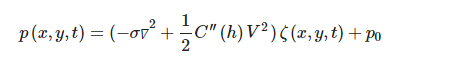
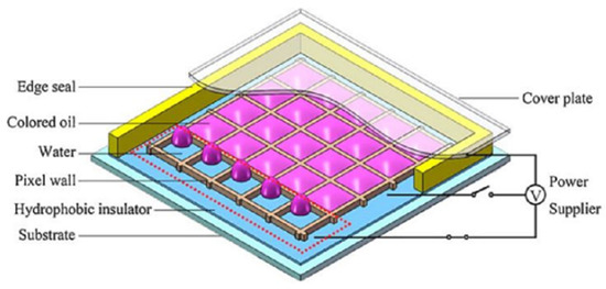
Figure 1. Schematic plot of electrowetting display. (Images are reproduced from reference [6] with the permission of Wiley-VCH Verlag).
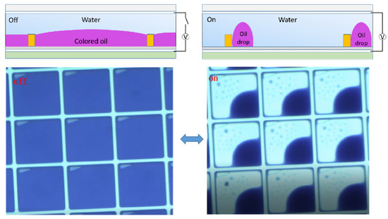
Figure 2. Experimental demonstration to show “on” and “off” state of electrowetting display (EWD) display units under electrowetting.
A positive value of this pressure promotes film growth. ζ(x,y,t) is the real-time interfacial location. C′′(h) is the second derivative of the capacitance of the oil film with an undisturbed thickness of h. In Figure 3, it is theoretically shown that the applied electric signal leads to the generation of a cascade of voltage dependent wave modes. A large voltage or a small oil film thickness will make the interface unstable, and consequently lead to the rupture of the oil film. In the course of validating the theory, it was experimentally observed that a number of undulation modes appear prior to film rupture, and the rupture location does not correspond to the maximum electric field strength in the case of the standard convex water/oil interface used in working devices. These findings provided an improved understanding of the dynamics of the oil rupture process inside the pixel after applying a voltage.
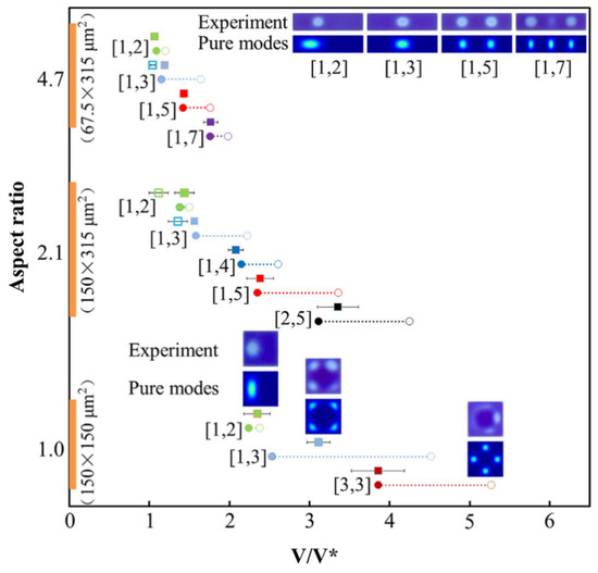
Figure 3. The experimentally observed wave modes and the theoretically expected sequences are compared in solid squares (the aspect ratio is defined as the ratio of width to the height of a pixel). (Images are reproduced from reference [3] with the permission of Springer Nature).
Furthermore, the dynamic behaviors of oil inks in the dewetting and rewetting processes, corresponding to the “on” and “off” switching of the pixel unit, were analyzed in an electro-fluidic pixel [4]. For “on” switching, the oil motion leads to oil film rupture (initiation stage), oil-dewetting and a slower droplet rearrangement stage (Figure 4). For “off” switching, fast oil wetting and reforming of the surface to the flat (dark) state (Figure 5) occur. A dynamic model derived from the energy balance perspective has been employed to describe the electro-fluidic response and corresponding optical performance inside an electro-fluidic based display (EFD) pixel. The variability of oil ink motion between on and off-switching and the optical response delay during the on-switching process have been well described and addressed.
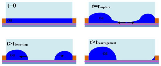
Figure 4. Stages in the on switching of an EWD pixel. (Images are reproduced from reference [4] with the permission of MDPI).

Figure 5. Stages in the off-switching process. (Images are reproduced from reference [4] with the permission of Elsevier).
According to the theoretical approach of static and dynamic conditions for oil ink in confined pixels, this provided a straightforward approach to describe the complex electro-fluidic switching dynamics under electrowetting modulation, which may guide the further optimization of EFD device design and driving schemes.
This entry is adapted from the peer-reviewed paper 10.3390/mi12020206
References
- Cho, S.K.; Moon, H.J.; Kim, C.J. Creating, transporting, cutting, and merging liquid droplets by electrowetting-based actuation for digital microfluidic circuits. J. Microelectromech. Syst. 2003, 12, 70–80.
- Hayes, R.A.; Feenstra, B.J. Video-speed electronic paper based on electrowetting. Nature 2003, 425, 383–385.
- Tang, B.A.; Groenewold, J.; Zhou, M.; Hayes, R.A.; Zhou, G.F. Interfacial electrofluidics in confined systems. Sci. Rep. 2016, 6, 7.
- Zhou, M.; Zhao, Q.; Tang, B.; Groenewold, J.; Hayes, R.A.; Zhou, G.F. Simplified dynamical model for optical response of electrofluidic displays. Displays 2017, 49, 26–34.
- Schift, H. Nanoimprint lithography: An old story in modern times? A review. J. Vac. Sci. Technol. B 2008, 26, 458–480.
- Chen, X.; Jiang, H.; Hayes, R.A.; Li, X.; He, T.; Zhou, G. Screen printing insulator coatings for electrofluidic display devices. Phys. Status Solidi A—Appl. Mat. 2015, 212, 2023–2030.
- Guo, Y.Y.; Yan, J.F.; Shen, Z.P.; Jiang, H.W.; Tang, B.; Deng, Y.; Henzen, A.; Zhou, R.; Zhou, G.F. Electrofluidic displays based on inkjet printing and phase change filling. J. Micromech. Microeng. 2020, 30, 9.
- Xiaotao, L.; Pengfei, B.; Jinwei, G.; Guofu, Z. Effect of Pixel Shape on Fluid Motion in an Electrofluidic Display. Appl. Mech. Mater. 2014, 635–637, 1159–1164.
- Massard, R.; Mans, J.; Adityaputra, A.; Leguijt, R.; Staats, C.; Giraldo, A. Colored oil for electrowetting displays. J. Inf. Disp. 2013, 14, 1–6.
- Chiang, H.-C.; Tsai, Y.-H.; Yan, Y.-J.; Huang, T.-W.; Mang, O.-Y. Oil defect detection of electrowetting display. Opt. Eng. Appl. 2015, 9575, 957514.
- Zhang, H.; Liang, X.-l. Bistable electrowetting device with non-planar designed controlling electrodes for display applications. Front. Inf. Technol. Electron. Eng. 2019, 20, 1289–1295.
- Dou, Y.; Tang, B.; Groenewold, J.; Li, F.; Yue, Q.; Zhou, R.; Li, H.; Shui, L.; Henzen, A.; Zhou, G. Oil motion control by an extra pinning structure in electro-fluidic display. Sensors 2018, 18, 1114.
- Yi, Z.C.; Huang, Z.Y.; Lai, S.F.; He, W.Y.; Wang, L.; Chi, F.; Zhang, C.F.; Shui, L.L.; Zhou, G.F. Driving Waveform Design of Electrowetting Displays Based on an Exponential Function for a Stable Grayscale and a Short Driving Time. Micromachines 2020, 11, 313.
- Yi, Z.; Feng, W.; Wang, L.; Liu, L.; Lin, Y.; He, W.; Shui, L.; Zhang, C.; Zhang, Z.; Zhou, G. Aperture Ratio Improvement by Optimizing the Voltage Slope and Reverse Pulse in the Driving Waveform for Electrowetting Displays. Micromachines 2019, 10, 862.
- Zhang, X.M.; Bai, P.F.; Hayes, R.A.; Shui, L.L.; Jin, M.L.; Tang, B.; Zhou, G.F. Novel Driving Methods for Manipulating Oil Motion in Electrofluidic Display Pixels. J. Disp. Technol. 2016, 12, 200–205.
- Yi, Z.C.; Liu, L.W.; Wang, L.; Li, W.; Shui, L.L.; Zhou, G.F. A Driving System for Fast and Precise Gray-Scale Response Based on Amplitude-Frequency Mixed Modulation in TFT Electrowetting Displays. Micromachines 2019, 10, 732.
- Mugele, F.; Baret, J.C. Electrowetting: From basics to applications. J. Phys. Condens. Matter 2005, 17, R705–R774.