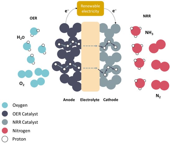
The application of protonic ceramic electrolysis cells (PCECs) for ammonia (NH3) synthesis has been evaluated over the past 14 years. While nitrogen (N2) is the conventional fuel on the cathode side, various fuels such as methane (CH4), hydrogen (H2), and steam (H2O) have been investigated for the oxygen evolution reaction (OER) on the anode side. Because H2 is predominantly produced through CO2-emitting methane reforming, H2O has been the conventional carbon-free option thus far. Although the potential of utilizing H2O and N2 as fuels is considerable, studies exploring this specific combination remain limited.
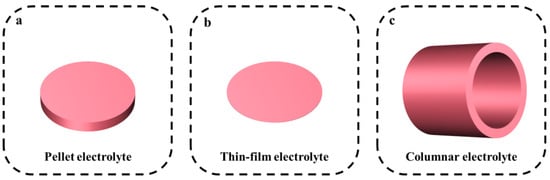
PCEC fabrication technologies are being developed extensively, thus necessitating a comprehensive review. Several strategies for electrode fabrication, deposition, and electrolyte design are discussed herein. The progress in electrode development for PCECs has also been delineated. Finally, the existing challenges and prospective outlook of PCEC for NH3 synthesis are analyzed and discussed. The most significant finding is the lack of past research involving PCEC with H2O and N2 as fuel configurations and the diversity of nitrogen reduction reaction catalysts. This review indicates that the maximum NH3 synthesis rate is 14 × 10−9 mol cm−2 s−1, and the maximum current density for the OER catalyst is 1.241 A cm−2. Moreover, the pellet electrolyte thickness must be maintained at approximately 0.8–1.5 mm, and the stability of thin-film electrolytes must be improved.
- electrochemical ammonia synthesis
- protonic ceramic electrolysis cells
- hydrogen
- catalysts
- nitrogen reduction reaction
1. Introduction
- ●
-
At the anode, an electric current passes through water, thereby splitting water molecules into hydrogen (protons) and oxygen ions.
- ●
-
Reaction: 2H2O → O2 + 4H+ + 4e−
- ●
-
Electrons generated at the anode during water splitting are transported through an external electric circuit.
- ●
-
Protons generated at the anode during water splitting are transported through the electrolyte [18].
- ●
-
At the cathode, protons (H+) from the anode and nitrogen atoms react to produce NH3
- ●
-
Reaction: N2 + 3H+ + 3e− → NH3
2. PCEC Design Strategies
2.1. Electrolyte Design Strategies
| Electrolyte | Method | Conductivity (S cm−1) | Thickness (mm) | Reference |
|---|---|---|---|---|
| SrCe0.95Yb0.05O3−δ | sol–gel | Unknown | 1.5 | [41] |
| BaZr0.8−x−yCexNdyY0.1Yb0.1O3−δ | Pechini method | 500 °C: 3.77 × 10⁻⁴ | 0.8–1.5 | [42] |
| BaZr0.85Y0.15O3−δ | hydrothermal process | 600 °C: 2.5 × 10⁻³ | 1.6 | [43] |
| Electrolyte | Method | Conductivity (S cm−1) | Thickness (µm) | Reference |
|---|---|---|---|---|
| BaCe0.7Zr0.1Y0.2 | co-precipitation solid-state reaction dip-coating |
650 °C: 2.8 × 10⁻² | ~20 | [45] |
| BaCe0.8Y0.2−xNdxO3−δ | citrate–nitrate combustion | 350 °C: 8.5 × 10⁻³ | ~20 | [46] |
| BaCe1−xInxO3−δ | auto-combustion reaction | 700 °C: 5 × 10⁻³ | 20–25 | [47] |
| BaZr0.1Ce0.7Y0.1Yb0.1 | solid-state reaction | 500 °C: 1.2 × 10⁻² | 10 | [48] |
| BaHf0.8Yb0.2O3−δ | pulsed laser deposition (PLD) | 500 °C: 2.5 × 10⁻³ | 110 | [48] |
| BaZr0.1Ce0.7Y0.1Yb0.1 | solid-state reaction | 500 °C: 1.3 × 10⁻² | ~10 | [22] |
| BaZr0.4Ce0.4Y0.1Yb0.1 | solid-state reaction | 500 °C: 5.6 × 10⁻³ | ~15 | [21] |
| BaZr0.2Ce0.6Y0.1Yb0.1O3−δ | Pechini method inkjet printing |
600 °C: 24.39 | 1 | [49] |
| BaCe0.5Zr0.35Y0.15O3−δ | citric nitrate method PLD |
Unknown | 2–4 | [50] |
| BaZr1−x−yCexYyO3 | ultrafast microwave-assisted sintering tape casting |
Unknown | ~12 | [51] |
| BaZr0.2Ce0.6Y0.2O3 | solid-state reaction spin coating |
800 °C: 1 × 10⁻² | ~7 | [52] |
| BaCe0.55Zr0.3Y0.15O3−δ | screen printing | Unknown | ~2.5 | [53] |
2.2. Electrode Design Strategies
| Cathode | Deposition Method | Thickness (µm) |
Reference |
|---|---|---|---|
| La0.6Sr0.4Co0.2Fe0.8O3−δ | Unknown | 44 | [24] |
| Ag | - | 4 | |
| Pt | - | 8 | |
| Fe | doctor blade | 15–25 | [26] |
| 10-Fe-BCY | doctor blade | 15–25 | |
| 0.5W-10Fe-BCY | doctor blade | 15–25 | |
| PrBa0.5Sr0.5Co1.5Fe0.5O5+δ | - | 10–20 | [36] |
| Ru–Ag/MgO | Unknown | - | [41] |
| Ni-BCYR | - | - | [63] |
| NdBa0.5Sr0.5Co1.5Fe0.5O5+δ (NBSCF)-BZCYYb | drop coating | 15 | [64] |
| Pr2NiO4-BZCY | screen printing | 13 | [65] |
| PrCo0.05Ni0.5O3−δ | tape casting | 29 | [66] |
| Ba0.9Co0.7Fe0.2Nb0.1O3−δ | screen printing | 15 | [67] |
| Pr0.2Ba0.2Sr0.2La0.2Ca0.2CoO3−δ | spray coating | 20 | [68] |
| PrBa0.5Sr0.5Co1.5Fe0.5O5+δ | PLD | 20 | [69] |
| Gd0.3Ca2.7Co3.82Cu0.18O9−δ | screen printing | 30 | [70] |
4. Current Progress
The NRR and OER have been studied extensively; the catalysts used for these reactions are summarized in Tables 5 and 6, respectively.
Table 5. Notable NRR catalysts in PCECs for NH3 synthesis.
|
Cathode * |
Electrolyte |
NH3 Production Rate [mol cm−2 s−1] × 10−9 |
Thickness (µm) |
Reference |
|
La0.6Sr0.4Co0.2Fe0.8O3−δ |
BaZr0.8Y0.2O3−δ |
0.0850 |
44 |
[24] |
|
Ag |
BaZr0.8Y0.2O3−δ |
0.0490 |
4 |
|
|
Pt |
BaZr0.8Y0.2O3−δ |
<0.0010 |
8 |
|
|
Fe |
BaCe0.9Y0.1O3−δ |
14.000 |
15–25 |
[26] |
|
10-Fe-BCY |
BaCe0.9Y0.1O3−δ |
0.4200 |
15–25 |
|
|
0.5W-10Fe-BCY |
BaCe0.9Y0.1O3−δ |
0.5700 |
15–25 |
|
|
Ru–Ag/MgO |
SrCe0.95Yb0.05O3−δ |
0.0003 |
- |
[41] |
|
Ni-BCYR |
BaCe0.9Y0.1O3−δ |
0.0110 |
- |
[63] |
Based on Table 5, metallic catalysts evidently yield higher reaction rates. This could be attributed to two main factors. First, perovskite-based electrocatalysts may possibly be affected by degradation at the interface and thermal mismatch with the electrolyte, thus decreasing the performance [24]. Second, the electrochemical promotion of catalysis is more pronounced in pure metal catalysts with a higher effective double layer (S*eff) on their surfaces than in supported electrocatalysts [26]. However, pure metallic catalysts are typically expensive.
Ru is regarded as a suitable catalyst for thermochemical NH3 synthesis because of its peak position on Skulason’s volcano diagram, which shows that it requires a minimum potential for electrochemical NH3 synthesis. It has also been reported to be an ultra-efficient electrocatalyst for the NRR, with a lower reduction potential than that of Fe [71–75]. However, Ag is a more cost-effective option because of its natural abundance. Although noble-metal-based electrocatalysts exhibit favorable activity, efficiency, and selectivity, their practical application is inhibited by their high cost and scarcity [27]. Consequently, extensive research has been conducted on transition-metal-based electrocatalysts for the NRR. The NH3 synthesis rate of Pt catalysts can be primarily attributed to their strong HER activity [76,77]. At negative potentials, the surface of Pt nanoparticles tends to adsorb hydrogen atoms rather than nitrogen atoms, thus affecting the overall performance [78].
Table 6. Notable OER catalysts in PCECs for NH3 synthesis.
|
Anode |
Electrolyte |
Current Density @1.3 V and 550 °C [A cm−2] |
Thickness (µm) |
Reference |
|
Pr0.2Ba0.2Sr0.2La0.2Ca0.2CoO3−δ |
BaZr0.1Ce0.7Y0.1Yb0.1O3−δ |
−0.800 |
20 |
[68] |
|
PrBa0.5Sr0.5Co1.5Fe0.5O5+δ |
BaZr0.4Ce0.4Y0.1Yb0.1O3−δ |
−1.059 |
20 |
[69] |
|
Gd0.3Ca2.7Co3.82Cu0.18O9−δ |
BaZr0.1Ce0.7Y0.1Yb0.1O3−δ |
−1.241 |
30 |
[70] |
Considering NH3-producing PCECs, most studies have only focused on the NRR, whereas the OER has been overlooked. The NH3 synthesis reaction is typically performed at 475–600 °C [24]. Pei et al. briefly summarized the OER performance at a cell voltage of 1.3 V and operating temperature of 550 °C [67].
Currently, transition metals, particularly compounds based on Fe, Co, and Ni, have demonstrated remarkable catalytic activity for the OER [79]. A successful method to enhance the OER activity involves altering the surface electronic structure through the addition of supporting materials to the active metal (Fe, Co, or Ni). This strategy has attracted attention, particularly with reference to multi-metal materials such as high-entropy perovskites, because they provide numerous possibilities for modifying the characteristics and improving the catalytic performance [80].
Among multi-metal materials, Co-based double perovskite oxides are notable for their rapid ion diffusion and enhanced surface catalysis, resulting in high electrochemical performance in single cells [35,69,81]. Various studies have explored the application of OER catalysts in PCECs (Table 6). For example, Gd0.3Ca2.7Co3.82Cu0.18O9−δ exhibits the highest current density owing to various factors, including abundant oxygen vacancies in the central Co–O layer of the Ca3Co2O3 rock–salt subsystem, which alters the electronic charge carrier concentration. The needlelike grain morphology aids in the complex flow of the reaction components via triple conduction and open diffusion paths [70].
Despite the promising characteristics of Co-based double perovskite oxides, these high-entropy perovskite oxides have disadvantages such as instability, thermal mismatch, and high cost, which limit their widespread implementation [35,69,81,82]. Thermal mismatch occurs when the OER catalyst and electrolyte materials have different coefficients of thermal expansion (CTE). The CTE indicates the extent to which a material expands when exposed to changes in temperature. If the OER catalyst and electrolyte have significantly different CTE, they may expand at different rates as the temperature changes [83]. Therefore, catalysts with compatible mechanical properties need to be used.5
5. Conclusions
This review presented a comprehensive outline of the design strategies for PCECs aimed at enhancing electrochemical NH3 synthesis. The mechanisms of the reactions involved were delineated, and design strategies for PCECs were investigated. This review provides novel insights into catalyst development for the NRR and OER. The following points summarize our findings and recommendations to further develop this technology.
Electrolytes must be further developed in terms of their architecture and thickness. For electrodes, understanding the underlying reaction mechanisms is essential. Co-based double perovskite oxides display rapid ion diffusion and improved surface catalysis, resulting in excellent electrochemical performance in individual cells. However, their application is challenging owing to high-entropy perovskite instability, thermal mismatch, and high cost. Computational analysis is indispensable when investigating the reaction mechanisms, particularly in the context of employing high-entropy perovskites as OER catalysts. Based on this review, we recommend the following research directions:
- A more scalable approach must be investigated to deposit Fe- and Co-based perovskite electrodes to reduce catalyst wastage.
- A more complex catalyst must be developed for the NRR because existing materials are not as advanced as OER catalysts.
- Stability and thermal mismatch issues for the OER must be addressed to decrease wastage and increase cell stability.
We believe that investigating more scalable methods, such as atomic layer deposition, will enhance the positive environmental impact of electrochemical catalysts used for NH2 synthesis. Similar to thermochemical NH3 synthesis catalysts, investigating various support materials for Fe- or Ru-based catalysts can be beneficial for the NRR. For further advancements in OER catalysts, the stability of the catalyst must be improved, and the thermal mismatch must be eliminated to enhance the overall efficiency of the PCEC.
This entry is adapted from the peer-reviewed paper 10.3390/en17020441