Your browser does not fully support modern features. Please upgrade for a smoother experience.
Please note this is an old version of this entry, which may differ significantly from the current revision.
Subjects:
Engineering, Civil
Among all the active confinement techniques, the use of pre-tensioned stainless steel straps has recently gained much attention. The flexibility of the stainless steel straps allows us to bend and pass them through the thickness of the masonry, thus creating a three-dimensional strengthening system between the two opposite facings.
- masonry walls
- CAM® system
- shear behavior
- reinforcement arrangement
1. General Information on the CAM® System
Among the various techniques of active reinforcement, this work focuses on the CAM® system (active confinement of masonry: CAM is the Italian acronym for active stitching of masonry) [16,17,18,19,20]. This system is an evolution of the strengthening method with post-tensioned horizontal and vertical tie rods [21,22,23,24,25,26,27]. The evolution consists of the strengthening elements of the CAM® system [28], which are stainless steel straps instead of metal bars. The stainless steel straps pass through the thickness of the masonry thanks to openings made in the masonry by core drilling.
When four stainless steel straps share the perforations and the loops have horizontal and vertical directions, the CAM® system replicates the reinforcement scheme with horizontal and vertical ties. In this case, known as a rectangular arrangement, the perforations divide the masonry wall into volume units in the shape of right parallelepipeds (Figure 1). Some theoretical analyses [11,29] revealed that the CAM® system adds confinement forces only in the transverse direction (Figure 1), except for volume units located near the free ends of the masonry wall. Recently, the numerical results of a FEM simulation [15] also confirmed that the confinement provided by the CAM® system to the wall is not isotropic.
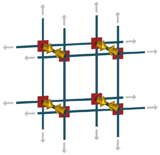
Figure 1. Stress transfer mechanism from the three-dimensional net of stainless steel loops placed in tension to the volume units of the masonry wall.
2. The Idea behind the Experimental Program
Seismic events impose two types of dominant loads on structures—the in-plane shear load (Figure 2a) and the out-of-plane bending load (Figure 2b)—which causes two types of dominant failure modes in URM structures [33,34]: the in-plane shear mechanisms and the out-of-plane bending mechanisms. The CAM® system with a rectangular arrangement (Figure 1) is suitable for increasing the out-of-plane strength of masonry walls when used in conjunction with other strengthening systems [29,35,36]. In the plane of the wall, however, the rectangular arrangement does not bring any increase in strength or stiffness. Both in-depth experimental tests [37] and recent numerical analyses [38], in fact, have shown that the rectangular arrangement of the stainless steel straps leads to an almost negligible increase in the strength of the shear-loaded masonry panels while providing a significant increase in ductility. The use of steel grids on both faces of the masonry wall, conversely, increases both the shear strength and the ductility, but the ultimate displacement achieved with the steel grids is lower than that achieved with the CAM® system [38].
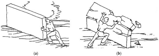
Figure 2. How a seismic event loads a wall (being oscillatory in nature, the seismic action acts, in an alternating manner, both in the direction of the load schematized as the action of a man on the wall, and in the opposite direction): (a) in the plane of the wall (shear loading in the midplane); (b) along the direction perpendicular to the plane of the wall (out-of-plane loading).
The lack of increase in shear strength with the CAM® system depends on the arrangement of the perforations, which makes the strengthening system labile to horizontal loads [29]. On the two wall facings, in fact, the straps of the rectangular arrangement form unbraced rectangular frame structures with hinged nodes. Under the action of horizontal forces, these nodes sway laterally exactly like the nodes of the simplified mechanical model in Figure 3a. Therefore, the perforations for the common passage of the straps are cylindrical hinges (Figure 3b), around which the loops connecting the two wall facings can rotate freely.
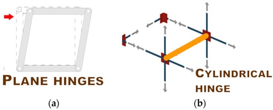
Figure 3. Lability of the CAM® system with a rectangular arrangement: (a) in the wall plane, according to the simplified mechanical model of an unbraced rectangular frame structure with hinged nodes and load oriented as the red arrow; (b) in the wall thickness, as represented by the orange element of the axonometric view (without the masonry blocks, to better appreciate the three-dimensional arrangement of the straps).
The in-plane lability of the strengthening system with a rectangular arrangement makes the CAM® system useless under horizontal loads. In order to allow the CAM® system with a rectangular arrangement to also improve the in-plane behavior of masonry walls subjected to seismic loads, it is therefore mandatory to eliminate its in-plane lability.
In rectangular frame structures, it is customary to cancel the horizontal displacement of the hinged nodes by bracing the structures along one or both diagonals, as shown in the simplified mechanical models of Figure 4a and Figure 4b, respectively. However, bracing is not the only possible solution to remedy the lability of the rectangular arrangement in the CAM® system: a 45° rotation of the straps makes the rectangular arrangement effective even in the plane of masonry walls.

Figure 4. Bracing of a rectangle made of hinged strips: (a) by adding a strip along a diagonal, which will prevent the rectangle from collapsing in the direction of the red arrow but not in the opposite direction; (b) by adding strips along both diagonals, which will prevent the rectangle from collapsing in either direction.
This entry is adapted from the peer-reviewed paper 10.3390/buildings13123027
This entry is offline, you can click here to edit this entry!