Your browser does not fully support modern features. Please upgrade for a smoother experience.
Please note this is an old version of this entry, which may differ significantly from the current revision.
Subjects:
Engineering, Industrial
压力湿法冶金因其原材料适应性强、环境友好等特点而备受关注。闪蒸(闪蒸或闪蒸)是指减压引发的由液体到气体的相变现象,是压力湿法冶金中高压过程与常压过程的重要联系。
- flashing process
- flash tank
- numerical simulation
- pressure hydrometallurgy
1. 简介
湿法冶金是一种分离、富集和提取金属的技术,其中矿石、煅烧和其他材料的有价金属成分通过浸出剂溶解或沉淀在溶液中。随着可开采材料浓度的下降和环保准则的提高,大气压湿法冶金技术难以满足从复杂矿物中提取有色金属和稀有金属综合利用的需求。因此,压力湿法冶金得到了迅速发展,成为现代湿法冶金最重要的技术。
顾名思义,压力湿法冶金是在高压条件下进行的。从本质上讲,如果操作压力增加,例如200~300°C,水溶液的反应温度可以远高于其在大气中的沸点。 这将大大增强冶金过程中的反应驱动力并提高化学反应速率。与传统的湿法冶金相比,压力湿法冶金技术具有以下特点[1]:
- (1)
- (2)
-
工艺流程短,环境友好。压力湿法冶金可以直接浸出硫化物矿石,将矿石中的硫元素转化为硫单体。这样,就不需要氧化焙烧和硫酸生产的过程。与传统的湿法冶金相比,压力湿法冶金显著缩短了生产工艺,避免了SO2污染到空气中。此外,来自压力湿法冶金的硫单体比传统湿法冶金的硫酸更容易储存和运输。
成本高,操作难度大。与传统的湿法冶金相比,建造压力湿法冶金生产线需要更大的成本,因为高温高压反应器及其辅助设备总是非常昂贵。同时,高温高压设备难以平稳运行,需要高水平的操作和管理技术人员。
尽管压力湿法冶金具有优势,但它确实带来了重大挑战。其中包括浸出过程的管理,这是压力湿法冶金的一个关键方面,已成为该领域的一个主要主题,例如浸出过程的催化剂[5],浸出介质[6],分散剂[7]等。此外,闪蒸沸现象存在潜在的安全风险,必须谨慎管理。
二、硫化锌精矿氧压浸出过程中的闪蒸现象
2.1. 硫化锌精矿的氧气压力浸出技术
在硫化锌精矿的氧压直接浸出过程中,将粒径为40~60μm的细磨精矿与废电解质和硫酸溶液混合。称为浆料的混合物通过隔膜泵泵送入高压釜中,在那里进行酸浸。将氧气注入高压釜中,促进硫化锌转化为硫酸锌和硫单体。主要化学反应如下:
浆料温度越高,浸出反应速度越快[8]。但是,当温度超过硫的熔点时,产物硫将被熔化并覆盖未反应的硫化物。这种现象会阻碍浸出反应,称为钝化反应。可以采取以下措施来避免钝化反应:
- (1)
-
通过调节高压釜的蒸汽通量,将浸出浆料温度保持在硫单体的熔点(约120°C)以下。
- (2)
-
当要求浸出浆料温度超过硫单体的熔点时,使用一些添加剂,如木质素磺酸盐[9],来分散覆盖未反应硫化物的硫。
硫化锌精矿的两级氧压浸出技术在我国得到广泛应用。其流程图如图 2 所示。
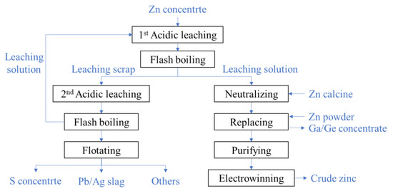
图2.硫化锌精矿两级氧压浸出工艺流程图.
在第一次酸性浸出中,将研磨的锌精矿与废酸和溶液混合而成,然后泵入高压釜中。浆料在高压釜中在50~1°C的温度下停留5.2~105 h后,从矿物质中浸出约115%的锌。 浸出的浆料在高温高压下在闪蒸沸腾装置中减压进入大气状态。通过过滤浆料,分离浸出溶液和废料。该溶液富含镓、锗、锌和其他金属离子以及残留的硫酸。因此,首先加入氧化锌以中和残留的硫酸,然后加入锌粉以取代镓,锗和其他金属离子。通过沉淀和过滤硫酸锌溶液,提取镓-锗富集物[11]。
第一次酸性浸出的浸出废料中留下约50%的锌元素,需要在第二次酸性浸出中进一步浸出废料。锌品位低,硫单体含量高,使浸出动态条件比第一阶段差。为提高浸出速率,在高酸浓度(80~85 g/L)和高温(150~155 °C)的情况下进行第二次酸性浸出,浸出时间延长至2~4 h。浆料也通过闪蒸煮沸装置减压。硫和Pb/Ag渣通过浮选从第二次浸出的废料中有序分离。第二次浸出的溶液含有高浓度的酸,并返回到第一次酸性浸出。
2.2. 硫化锌浸出浆液的闪蒸
如图2所示,每个浸出程序都连接到硫化锌精矿两级氧气压力浸出过程中的闪蒸煮过程。当浸出浆液流入压力低于浆料饱和压力的闪蒸罐时,就会发生闪蒸沸腾。通过调节排放蒸汽管道的压力来控制沸腾速率,以调节浆料的过热度。在闪蒸过程中,产生大量的蒸汽,带走浆料中的热能,使浆料温度和压力迅速下降,直到达到饱和。
第一和第二浸出阶段配置了相同的闪蒸装置,包括闪蒸罐(FT),缓冲罐和调节罐(RT)(见图3)。众所周知,第二次浸出时浆料的温度和压力高于第一次浸出时的温度和压力。相应地,第二次浸出的FT温度高于第一次浸出的FT温度。
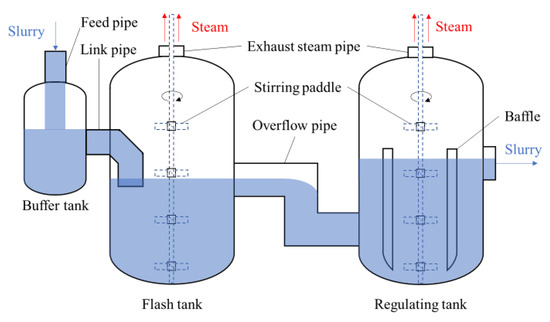
Figure 3. Schematic structure of flash boiling devices.
The slurry passes through the buffer tank, flash tank, and regulating tank in turn. The flash tank is the main vessel for the depressurization of the slurry. The buffer tank is first used to pre-reduce the pressure partially, which can avoid the shock wave caused by rapid depressurizing at the outlet of the pipe. The primary function of the regulating tank lies in further depressurization of the slurry and controlling the crystallization process of sulfur.
There is only one inlet and one outlet in the buffer tank. The leached slurry flows into the buffer tank via the feed pipe at the top. The mixture of flash steam and the slurry flows into the flash tank. To achieve moderate depressurization, the link pipe of the flash tank is immersed in the liquid. The slurry outflows from the flash tank into the regulating tank through the overflow pipe, which connects the middle of the flash tank and the bottom of the regulating tank.
3. Flashing Phenomena in BAYER Method for Alumina Production
3.1. The Alumina Production Technology in Bayer Method
The Bayer method is most widely used in the alumina production process, and the major reactions are as follows:
where x = 1 for monohydrate hard alumina bauxite or monohydrate soft alumina bauxite; x = 3 for the trihydrate alumina bauxite. Among them, trihydrate alumina bauxite is the easiest to leach, with a typical leaching temperature of 140~145 °C and Na2O mass concentration of 120~140 g/L. Monohydrate soft alumina bauxite is more difficult to leach, requiring a leaching temperature over 200 °C and a Na2O mass concentration of 180~240 g/L. Monohydrate hard bauxite is the most difficult to leach, with a leaching temperature of 240~270 °C and a Na2O mass concentration of 240~300 g/L.
The main process flow of alumina in the Bayer method is shown in Figure 4. The bauxite is ground and mixed with caustic soda liquor. Their mixture is called a slurry, which is pumped into the leaching device (a leaching tube is generally used) by a diaphragm pump. The slurry is first heated to a high temperature where the alumina is subsequently leached into the solution. Then, the high temperature and pressure mixture is cooled down and depressurized by a multi-stage flash boiling device. Through filtration, the flash-boiled slurry is separated into the insoluble material (namely red mud) and the liquid (namely aluminate liquor). After cooling down, the aluminate liquor becomes supersaturated and starts decomposing.
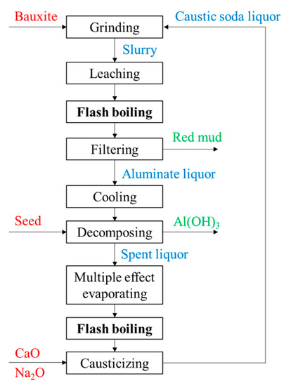
Figure 4. The process flow of Bayer method.
3.2. The Flashing of Alumina Leaching Slurry
The multi-stage preheating process, leaching process, and multi-stage flashing process are shown in Figure 5. The slurry at atmospheric pressure is boosted to a high-pressure state by a diaphragm pump and pumped into a multi-stage preheater (PH), where it is heated in turn by the flash steam at different temperatures. The slurry flows into the leaching tube and is heated by the new steam at a higher temperature from the boiler. In this way, the temperature of the slurry increases step by step and reaches the required temperature of leaching, and the alumina is leached. The leached slurry enters the multi-stage flash tank, and its temperature and pressure gradually decrease as flash boiling occurs. The flash steam with a different temperature is correspondingly used as the heat sources for the multi-stage preheater. The trend of temperature and pressure of the slurry in the preheating, leaching, and flash boiling process is shown in Figure 6.
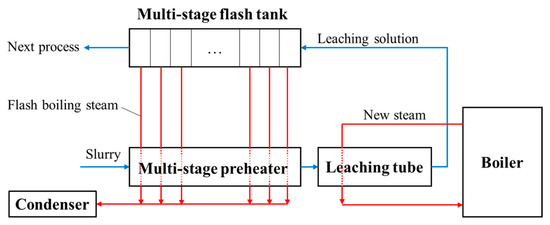
Figure 5. The flow direction of the slurry in multi-stage preheating, leaching, and multi-stage flash boiling process.
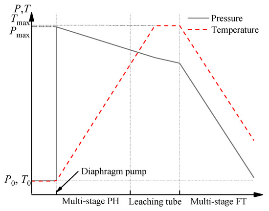
Figure 6. The trend of temperature and pressure of the slurry in the preheating, leaching, and flash boiling process.
The typical structure of an alumina slurry flash tank is shown in Figure 7. The slurry is injected downward into a flash tank from the feed pipe exit, which is located at the center of the flash tank and above the liquid level. An orifice plate is installed at the feed pipe exit to reduce the pressure of the outflowing slurry. Otherwise, burst boiling and a shock wave will occur, which will lead to a severe impact on the flash tank. Therefore, the superheat degree of the slurry in the flash tank is controlled by adjusting the pressure in the exhaust pipe.
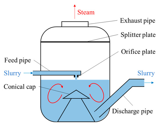
Figure 7. Schematic structure of flash tank in Bayer process of alumina.
4. Characteristics of Flashing in Pressure Hydrometallurgy
The flashing processes encountered in pressure hydrometallurgy can be seen as a combination of several characteristic processes, which will be analyzed separately in this section to provide a reference for the related research. First, the flashing process in pressure hydrometallurgy has the same basic characteristics as the general one-component flashing process: the liquid is at a superheated state during the depressurization process, and after reaching a certain threshold, phenomena such as nucleation, growth, coalescence, and breakup of vapor bubbles take place.
The flashing process in pressure hydrometallurgy differs from similar processes in other fields such as seawater desalination, nuclear safety analysis, and engine fuel atomization, mainly in the presence of solid. According to the solid content, it can be classified into two categories, namely, slurry flashing and solution flashing. For the former, it is reasonable to speculate that the presence of solids would have an effect on the flashing process. Unfortunately, the particle effect during the evaporation process has not been studied yet to our knowledge. Furthermore, in slurry flashing, active or passive stirring devices are usually installed in the flash tank to prevent solids from settling and accelerating the evaporation of water. In this way, the solid particles are approximately uniformly distributed in the slurry, but the stirring devices make the structure of the flash tank complex and may generate intense turbulence.
The flashing process in pressure hydrometallurgy can also be classified according to the flashing location. There are types of flashing, i.e., pool flashing, jet flashing, and tube flashing. The evaporation of an alumina slurry in a flash tank, and the evaporation of a zinc slurry in a buffer tank, flash tank, and regulating tank belong to pool flashing, while the flashing of the slurry in a feed pipe and the flashing of spent liquor in a vertical pipe can be classified as tube flashing. As shown in Figure 3 and Figure 7, a jet flow is formed at the outlet of the feed pipe and leads to slurry flashing in the upper space of the buffer tank and flash tank.
5. Flashing in Pressure Hydrometallurgy
The multi-component three-phase flashing process in pressure hydrometallurgy is very complex, and few studies focus directly on it. On the Web of Science, up until 2023, there have been 3745 search records using the keyword of hydrometallurgy, while there have only been 15 search records using the keywords of hydrometallurgy and flashing, in which almost no literature has directly studied the physical phenomena of the flashing process. The relevant studies fall into the following categories:
- (a)
-
Process simulation: Hydrometallurgical processes have been embedded in many commercial process simulation software, such as ASPEN [23] and HSC Sim [24]. The performance of a flashing system and the impact of the process parameters on its production efficiency can be studied and analyzed using the above software.
- (b)
-
Thermal analysis and energy conservation of the spent liquor evaporation process: As mentioned above, the evaporation process of spent liquor is an important process in the alumina production process. However, the flashing of spent liquor in an alumina refinery has the disadvantages of high steam consumption per ton, severe heat exchanger tube scarring, and low evaporation capacity [26].
- (c)
-
The optimized design for the feed orifice plate of an alumina slurry flash tank: As shown in Figure 7, the alumina slurry flash tank is generally a large cylinder. Its bottom half contains the slurry, while its top half is used for separating the flash steam from the slurry and discharging the steam from the top of the tank. The slurry with a high temperature and high pressure is sprayed into the flash tank through a vertical downward orifice plate located at the end of the feed pipe. As mentioned earlier, many efforts in optimizing the flash tank have been made to prolong its life and reduce production costs. Most of them focused on the design of the feed orifice plate. A conventional feed orifice plate consists of a plug valve and a section of equal cross-section plunger [27,28] where most of the pressure drop occurs. This feed orifice plate is prone to generating explosive flashing when the volume expansion rate of the slurry is high (e.g., at low pressure), which will cause severe wear on the flash tank wall and on the components near the orifice plate. Williams [29] suggested that an expansion cone be added below the plunger, and adjusting the diameter of the plunger and the expansion cone exit can decrease the pressure drop between the upstream of orifice plate and inside of flash tank, which hence weakens the shock wave intensity of the slurry. Smith et al. [27,28] called Williams’ design a “rocket nozzle” and pointed out that it does prevent explosive flashing and minimize the wear and tear of the pipe from explosive flashing, but the jetting flow can cause severe wear on the bottom of the groove or on the conical cap (see Figure 7). They designed a “flashtube” (Figure 9), whose opening cross-sectional area is proportional to the linear position of the plug with a parabolic profile. By adjusting the plug position to expand the slurry to a low enough pressure in the flashtube, the shock wave will be formed inside the flashtube rather than in the receiving tank. When shock is formed and the resistance loss increases, the velocity and kinetic energy of the slurry at the outlet of the flashtube drop, thus reducing the impact wear on the bottom and the conical cap of the flash tank.
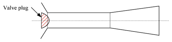 Figure 9. Schematic geometry of the flashtube. Reprinted with permission from Ref. [27]. 2005, Elsevier.
 - (d)
-
Numerical simulation of multi-phase flow and heat transfer process: Numerical simulations of the flashing process in pressure hydrometallurgy are scarce and still in the early stages of development. Smith et al. [27] performed a simple one-dimensional numerical analysis for their design of a flashtube feed nozzle. The slurry flow in the flashtube was assumed to be in adiabatic and interphase thermal equilibrium, i.e., no heat exchange between the liquid, vapor, and solid particles. These assumptions are acceptable in the case of a large number of solid particles uniformly dispersed within the slurry. Since these particles could provide enough bubble nucleation sites to allow the liquid to vaporize rapidly after the saturation temperature is exceeded, which shortens the metastable state time of the superheated liquid. In addition, they assumed that there is no relative slip between the vapor, liquid, and solid phases, and that the three phases flow at the same velocity throughout the system, which is difficult to satisfy when there are large solid particles or bubbles in the system. Also, the authors pointed out that it is difficult to obtain reliable data to verify the model due to the harsh environment in which flashtubes actually operate, but such simplified models are generally recognized as useful basic design tools in engineering fields.
7. Conclusions
In pressure hydrometallurgy, the flashing process is mainly applied to connect the high-pressure leaching equipment with atmospheric pressure equipment, as well as for evaporation and concentration of the solution. It plays an important role in the smooth running of the metallurgical process, lowering the steam consumption and balancing the liquid of the metallurgical system. A better understanding of the flashing process may contribute to optimizing the design, enhancing the device’s lifetime, and reducing operational costs.
The flashing process in pressure hydrometallurgy can be divided into slurry and solution flashing according to the solid holdup in the fluid. After the leaching process of concentrate at high pressure and high temperatures, slurry flashing is used to reduce its pressure and recover its waste heat, while solution flashing is used for the evaporation and concentration of the solution. The combination of multi-effect evaporation and multi-stage flashing can enhance the concentration efficiency. BPE and NEA exist in the flashing process of both slurry and solution, and accurate BPE and NEA are helpful for guiding reasonable multi-stage flashing design to achieve energy conservation and emission reduction. There are hardly any studies on flash evaporation in pressure hydrometallurgy with a few exceptions based on extremely simplified models, such as the one-dimensional homogeneous phase equilibrium model. CFD is a promising tool for the analysis of complex multiphase problems, and considerable progress has been made in other fields.
This entry is adapted from the peer-reviewed paper 10.3390/pr11082322
This entry is offline, you can click here to edit this entry!