In RAPS systems that utilize solar and hydrogen power, which typically include photovoltaic modules, a proton exchange membrane (PEM) electrolyzer, hydrogen gas storage, and PEM fuel cells, the cost of these systems is currently higher compared to conventional RAPS systems that employ diesel generators or batteries. URFCs offer a potential solution to reduce the expenses of solar hydrogen renewable energy systems in RAPS by combining the functionalities of the electrolyzer and fuel cell into a single unit, thereby eliminating the need to purchase separate and costly electrolyzer and fuel cell units. URFCs are particularly well-suited for RAPS applications because the electrolyzer and fuel cell do not need to operate simultaneously. In electrolyzer mode, URFCs function similarly to stand-alone electrolyzers. However, in fuel cell mode, the performance of URFCs is inferior to that of stand-alone fuel cells.
fuel cells
hydrogen energy
URFC
1. URFCs History
In 1839, Sir William Grove was recognized as the pioneer who initially conceptualized the fuel cell. The popularity of fuel cells experienced significant growth during the 1950s, primarily driven by the demand for secure, space-efficient, and relatively lightweight power generation technology in spacecraft. Hydrogen and oxygen were the primary elements used in fuel cells for the space programs of the United States and the Soviet Union. However, Sir William Grove also recognized the potential of a reversible cell that could both generate electrolytes and produce energy, making it a valuable component for energy storage systems. The gases have the potential to be used to store water in water tanks and power in fuel cells. Through a lifetime test of a single-cell PEM URFC in 1973, General Electric (GE) provided preliminary proof for the unitized regenerative fuel cell (URFC) theory. The test demonstrated significant cell reversal without membrane destruction, similar to Nafion 120 by DuPont, along with the catalyst [18].
In 1992, Aero Vironment Inc. and the Lawrence Livermore National Laboratory (LLNL) began a collaborative effort to investigate the feasibility of unitized regenerative fuel cells (URFCs) as a potential energy storage solution for HALE-SRA (High Altitude Long Endurance Solar Rechargeable Aircraft). The research for this project received financial backing from the Ballistic Missile Defense Organization (BMDO). In ordinary aircraft, electricity from solar cells was fed to the fans throughout the day, with additional URFCs running in (electrolyzer mode) E-mode to supply hydrogen and oxygen as shown in Figure 1. The hydrogen and oxygen gasses emanating from the URFC have been riffed to URFC, now running (fuel cell mode) FC-mode in order to keep the propellers moving and pushing the aircraft overnight.
Figure 1. URFC-based energy storage solar-powered aircraft model [18].
In 1993, LLNL designed and built the first portable URFC demonstration unit with the help of Hamilton Standard [19]. The fuel cell enters fuel cell mode by turning on the URFC after being charged for a brief period, ranging from seconds to minutes. The URFC presentation was tremendously successful, and as a result, its duplicates received invitations to take part in international events where they were inspected by academics, decision-makers, and financial industry experts. Proton energy systems recognized the value of this early sale of URFC toys and created its own toys for sale as shown in Figure 2 with less than 5 watts of mobile applications [20]. The development of URFC technologies with applications resembling those in aircraft began in the late 1990s. LLNL used the reversible PEM technology in the aerospace industry, which was developed by the Hamilton Standard (HS) over the difficult problem of solar aircraft performance at night before 1998 [19].
Figure 2. Demo unit of standard URFC LLNL/Hamilton (a), Demo unit of URFC Proton (b) [19].
Hydrogen and oxygen-based URFC is an ideal combination for rocket engines used by vehicle launchers, such as the main space shuttle engine. Figure 3 represents the demo unit of standard URFC LLNL/Hamilton which is used in the ship.
Figure 3. Demo unit of standard URFC LLNL/Hamilton [19].
In the mid-1990s, the Lawrence Livermore National Laboratory (LLNL) achieved a successful substitution of the primary fuel cell experiment (FC), measuring 46 cm2 in active area, with a unitized regenerative fuel cell (URFC). Additionally, LLNL has further developed a URFC system specifically designed for lightweight pressure vessels, catering to terrestrial vehicles with non-emission requirements.
2. Regenerative Fuel Cells (RFCS)
An electrolyzer and a fuel cell can both be produced by one device or by a networked system [21]. A reversible fuel cell (RFC) uses electrolysis to separate the components of water into hydrogen and oxygen as the main reversible process, as depicted in Equation (1):
H2O + energy ↔ 2H+ + ½ O2 + 2e−.
Research has been dedicated to investigating reversible fuel cells (RFCs) that center around water-splitting reactions, with specific emphasis on zinc–oxygen and hydrogen–halogen reactions [22]. The electrolyzer mode (E-mode) of an RFC works by splitting liquid water into hydrogen and oxygen using the electrical input of the cell. The RFC may operate as a fuel cell (FC) and generate electricity while producing water since these gases are stored and can be reintroduced into it. Another alternative is to solely collect hydrogen, in which case the RFC would require atmospheric oxygen to function as a fuel cell. Thus, the reversibility of water dissociation and reforming processes is a fundamental tenet of RFC theory. RFCs are a comprehensive energy storage system for future use, in combination with hydrogen and oxygen storage systems when oxygen is supplied by air. As a result, RFCs have potential in areas like spacecraft, satellites, underwater submarines, aircraft, terrestrial systems [23,24], and storage of electricity at the local level [25].
Figure 4 depicts the main two types of RFCs.
Figure 4. Types of RFCs.
Discrete Regenerative Fuel Cells: In this setup, the device responsible for electrolysis is distinct from the device utilized as fuel cells; however, both devices are combined into a one-unit system, as illustrated in Figure 5. Complete configuration, known as Discrete Regenerative Fuel Cells (DRFCs), encompasses a water treatment system, a control network, and a gas storage network, forming a self-contained energy storage facility. One notable advantage of DRFCs, in comparison to separate electrolyzers, hydrogen storage units, and fuel cells, is the consolidation of all functional components within a compact system. This integration allows DRFCs to serve as a standalone alternative for electricity storage and operate directly from batteries.
Figure 5. Block diagram of DRFCs.
Furthermore, DRFCs offer the capability to halt the flow of water, enabling the return of water to the electrolyzer’s water storage when operating in fuel cell mode. This feature holds significant value for installations in space, aircraft, or underwater applications where water recycling is necessary. Moreover, it proves particularly beneficial for sustainable energy utilization in regions with limited water supply. By optimizing the performance and cost-effectiveness of both the electrolyzer and fuel cells, this research aims to enhance their efficiency. Additionally, the cell’s capacity can be flexibly adjusted in two directions, allowing simultaneous operation in both modes.
2.
Unitized Regenerative Fuel Cell: URFCs, unlike DRFCs, are devices designed with the capability to operate in two modes: E (electrolyzer) mode and FC (fuel cell) mode. In contrast to DRFCs, URFCs utilize a single physical cell, as depicted in Figure 6 that serves both as an electrolyzer and a fuel cell. The fundamental electrochemical reaction of this reversible bi-functional unit is represented by Equation (1). While in FC mode, the released heat and power from the reaction of hydrogen and oxygen gases are used to regenerate water, whereas URFCs enable the conversion of water into hydrogen and oxygen in E-mode [26].
Figure 6. Block diagram of URFCs.
URFCs often start off in E-mode, which is where the processing of hydrogen and oxygen takes place. Then, for FC-mode operation, these gases are taken out and put back in the same unit. Water is supplied by flow fields in E-mode, where it is electrolyzed into oxygen and hydrogen under the influence of the applied voltage during cell loading and catalyst activity. Water interacts with the catalyst to release protons and electrons. Positively charged ions (Protons) are attracted toward the cathode and travel through the ion exchange membrane whereas negatively charged ions (electrons) travel towards the other end of the cell through an electric circuit. At the cathode, electrons combine with hydrogen protons to form a stabilized atom of hydrogen.
The half-cell processes observed in E-mode are represented by Equations (2)–(4):
Anode’s chemical reaction is represented in Equation (2):
H2O → 2H+ + 2 e− + ½ O2.
Cathode’s chemical reaction is represented in Equation (3):
2H+ + 2 e−→ 2H2. (3)
The overall electrochemical reaction is shown in Equation (4):
H2O → H2 + ½ O2.
The processes of hydrogen oxidation and oxygen reduction take place in FC-mode operation [27], as illustrated by Equations (5)–(7):
Anode’s chemical reaction is represented in (5):
H2 → 2 H+ + 2 e−.
Cathode’s chemical reaction is represented in Equation (6):
½ O2 + 2 e− +2 H+→ H2O.
The overall electrochemical reaction is shown in Equation (7):
H2 + ½ O2 → H2O.
URFCs possess the ability to serve as a backup battery by transforming electrical energy into chemical energy while being charged. When in discharge mode, the URFCs device functions as a fuel cell, directly converting the stored reactants into electricity [28].
3. Focus on PEM for URFCS
There is a significant emphasis on proton exchange membranes (PEMs) in the development of URFCs. The majority of URFCs utilize solid polymer PEMs as their electrolyte [29,30,31,32]. The invention of PEMs can be attributed to Willard Thomas Grubb and Lee Niedrach, who made the breakthrough in the early 1960s. These solid fluoro polymer membranes are chemically modified and incorporate sulfonic acid groups, which readily release hydrogen protons [33], as depicted in Equation (8).
SO3H → SO3− + H+.
The ionic model employed in proton exchange membranes (PEMs) enables the permeation of water through the membrane while preventing the production of hydrogen and oxygen gases. Consequently, the water protons in the form of hydronium (H3O+) are able to move freely, while the SO3H groups remain stable within the polymer side chains. When an electric field is applied to the membrane, the water protons are drawn towards the negatively charged electrode. This unique behavior of the membrane, acting as a conductor for power transfer, classifies it as a proton conductor.
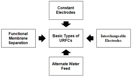
4. Basic Types of URFCs
Figure 7 represents the flow chart of various types of conventional URFCs and the details of these URFCs are illustrated below:
Figure 7. Flow chart of URFCs Types.
1.
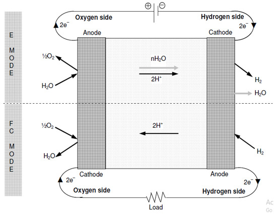
Constant Electrode Type:
In the prevalent configurations of URFCs, as depicted in Figure 8, the electrode responsible for hydrogen production and consumption during E mode is commonly referred to as the “hydrogen electrode”. Conversely, the other electrode is involved in the formation and absorption of oxygen, earning the designation of “oxygen electrode”. These electrodes permit the passage of current in both modes by serving as the cathode and anode. For this type of URFCs, the terms oxygen and hydrogen electrodes are used in the present work instead of “cathode and anode”, and to avoid confusion.
Figure 8. Basic Diagram of Constant Electrodes.
In FC mode, it is necessary to support the opposite reaction of water formation. Therefore, the catalyst layer must work bi-functional. The development of URFCs requires addressing the crucial challenge of achieving bi-functionality since most catalysts exhibit a preference for one-way reactions and lack effectiveness in reverse reactions [34].
The hydrogen electro-catalyst layer must withstand the hydrogen formation reaction in E mode (refer to Equation (3) above) and the inverse separation of hydrogen molecules in FC mode. Fortunately, platinum serves as an effective catalyst for both the formation reaction and the splitting of hydrogen molecules, necessitating the catalyst layer to be bi-functional once more. Therefore, the basic design and cross-sectional problems of the material tend to achieve the double-function/bi-functionality of an oxygen electrode in terms of catalytic efficiency and reaction rate, rather than the hydrogen side. In addition, the formation reactions and water-splitting involve a series of intermediate reactions [35], which are much more complex than hydrogen side reactions. However, during E-mode, the generated oxygen combines with water vapors and is carried along, as illustrated in Figure 8.
2.
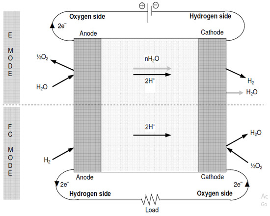
Interchangeable Electrodes:
The alternative properties of URFCs converts electrode that come into contact with oxygen and hydrogen and vary from method to method as shown in Figure 9. In this type of fuel cell, oxidation takes place both in the oxidation reaction (electron consumption), and in the reduction reaction (electron generation) by the same electrode (cathode). According to claims, in comparison to the initial category of URFCs mentioned in the preceding subsection, it was relatively simpler to identify a suitable catalyst and establish a stable electrode for this particular type. In particular, the utilization of platinum on both electrodes within the catalyst layer has proven effective in promoting the decomposition reaction at one electrode during E-mode and facilitating the formation of hydrogen at the other electrode during FC mode. However, catalytic materials can be applied to both electrodes in order to avoid water formation reactions. Thus, the two electrodes contain a mixture of catalysts, for the first type of URFCs rather than a single electrode.
Figure 9. Basic Diagram of Interchangeable Electrodes.
Another limitation of utilizing this method of electrode switching is the possibility of oxygen and hydrogen intermingling on both sides of the membrane. This mixing can lower the cell’s efficiency and raise safety concerns if the oxygen–hydrogen mixture exceeds its flammability limit. To address this problem, it is usually essential to flush the electrode region with an inert gas like nitrogen while transitioning modes to avoid any undesired mixing.
3.
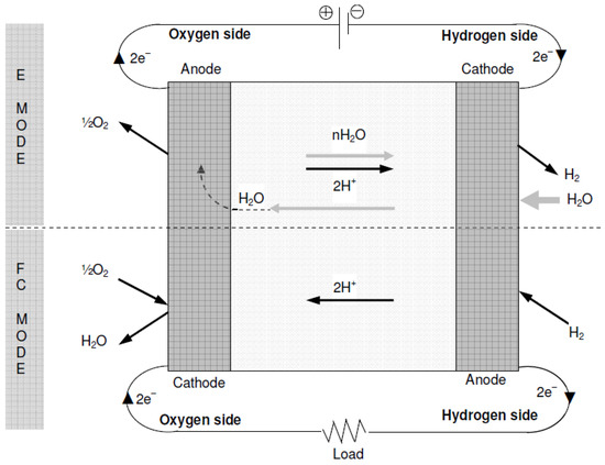
Alternate Water Feed:
Both of the mentioned design types involve the introduction of water into URFCs during E-mode, specifically at the oxygen electrode. However, there is an alternative approach where water is supplied to the hydrogen electrode, referred to as cathode feed. This method relies on the diffusion of water molecules through the membrane to supply water for the oxygen electrode’s water-splitting reaction, as shown in Figure 10. The benefit of this water supply method is that a single-phase separator on the hydrogen side is adequate for separating hydrogen gas from hydrogen vapor, since water is predominantly present in significant amounts at the hydrogen electrode [36]. At high current concentrations, the oxygen fraction is easy to dry, and the electrolysis reaction is suppressed. If water is supplied with oxygen, this part of the water is always high, and it cannot be drained.
Figure 10. Basic Diagram of Alternate Feed Water.
4.
Functional Membrane Separation:
Another type of URFC proposed by [37] separates the field with a single membrane from one part of the water-electrolyte and another part of the FC mode. Each channel supplies gas and water on both sides.
Let us know your experience and what we could improve.
Report an Issue
Is something wrong? Please let us know!
Other Feedback
Other feedback you would like to report.
Did you find what you were looking for?
Love
Like
Neutral
Dislike
Hate
0/500
Email
Do you agree to share your valuable feedback publicly on Encyclopedia’s homepage?
Webpage
Upload a screenshot (Max file size 2MB)
Submit
Back
Close
Quick Survey
Encyclopedia MDPI is conducting a targeted survey to identify the specific barriers hindering efficient
research. We invite you to spend 3 minutes defining the priorities for our next generation of structured
knowledge tools.

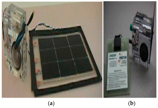
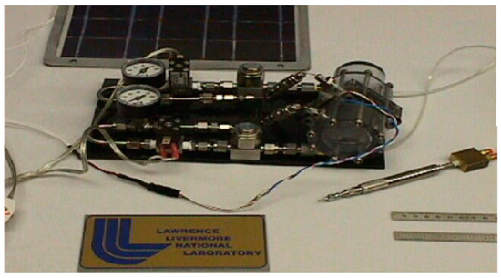
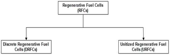
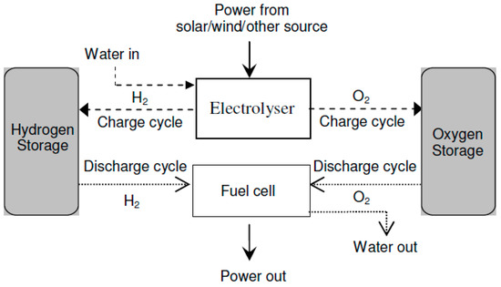
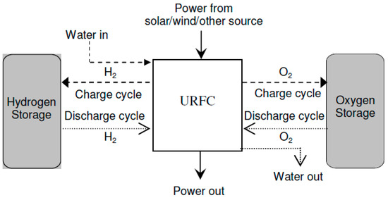 Figure 6. Block diagram of URFCs.