Your browser does not fully support modern features. Please upgrade for a smoother experience.
Please note this is an old version of this entry, which may differ significantly from the current revision.
Subjects:
Dentistry, Oral Surgery & Medicine
Sinus floor elevation (SFE) is a standard surgical technique used to compensate for alveolar bone resorption in the posterior maxilla. Such a surgical procedure requires radiographic imaging pre- and postoperatively for diagnosis, treatment planning, and outcome assessment. Cone beam computed tomography (CBCT) has become a well-established imaging modality in the dentomaxillofacial region. The following review is aimed to provide clinicians with an overview of the role of three-dimensional (3D) CBCT imaging for diagnostics, treatment planning, and postoperative monitoring of SFE procedures.
- CBCT
- maxillary sinus
- sinus floor elevation
1. Introduction
Alveolar bone atrophy in the maxillary posterior region is inevitable following tooth extraction, resulting in horizontal and vertical ridge resorption [1,2]. If a dental implant is inserted in bone having inadequate volume, there is a high risk of compromised implant stability and poor prognosis [3,4]. In order to compensate for reduced bone height and volume of the maxillary posterior region, sinus floor elevation (SFE) is performed for bone reconstruction. It involves lifting up of the Schneiderian membrane, which is usually followed by the placement of a bone graft [5,6,7,8,9].
The two main techniques for SFE are either a direct approach using a lateral window or indirect with the transalveolar technique. In the lateral window approach, an osteotomy is performed in the buccal wall of the maxilla, creating access through the lateral bone wall of the sinus cavity [10,11,12]. The transalveolar technique is a less invasive technique that was modified by Summers [13], where a transcrestal osteotome is applied to elevate the sinus floor, pushing bone substitutes beyond the level of the original sinus floor [14]. This technique has been recommended in areas with sufficient alveolar crest width and where a residual vertical bone height of ≥5 mm is available [15]. In cases where the alveolar bone height is less than 5 mm, the lateral window approach is recommended [16].
To date, various graft materials have been successfully used for SFE solely or in combination with each other [17], such as autograft [18,19,20,21] (intraoral: chin, retromolar region, mandibular ramus, maxillary tuberosity [22,23]; extraoral: iliac crest, fibula, tibia [24,25,26]), allograft [27,28,29] (fresh, frozen, freeze-dried bone [30,31]), xenograft [32,33,34,35,36] (deproteinized bovine bone [37,38,39]), and phytogenic material [39,40,41] (Gusuibu, coral-based bone substitutes, and marine algae).
Along with patient history and clinical examination, radiographic examination is an essential component of preliminary diagnostics, treatment planning, and outcome assessment in patients requiring SFE. Previously, two-dimensional (2D) panoramic radiography acted as a clinical standard. However, it suffers from certain inherent limitations, which can negatively impact the task at hand, such as magnification, distortion, and superimposition [16,42].
Three-dimensional (3D) preoperative imaging of the specific site of augmentation becomes a prerequisite in order to provide needed information about the morphologic characteristics and/or pathological conditions of the sinus and residual ridge [43,44,45]. Some studies have used computed tomography (CT) for the planning of sinus grafting [46] and precalculated the augmented bone volume needed [47,48,49,50]. However, the use of CT imaging is limited for most dental practitioners due to the high costs, large size of the device, and high radiation dose. To overcome these general limitations, 3D imaging in the form of cone beam CT (CBCT) has become a standard [43,44] for patients requiring maxillary sinus procedures. Recently, various CBCT imaging systems with low-dose protocols have also been made commercially available, which are not only affordable and compact to be used in a private dental practice but also provide 3D imaging with a lower radiation dose exposure to the patient [51,52].
2. Digital Workflow for SFE Procedures
In recent years, digital technologies and workflows have been introduced in the majority of dental medicine fields, including restorative dentistry, orthodontics, dental implantology, and maxillofacial reconstructive surgery [87]. Digital treatment planning workflow refers to the incorporation of computer-controlled components and dental technologies for assisting a clinician with the planning process. This digitization of workflows in clinical dentistry has overcome the limitations associated with traditional methods by offering improved precision of dental procedures, time-efficiency, and a higher standard of patient care [88,89,90].
2.1. Virtual Modelling
Generally, CBCT images are saved in a Digital Imaging and Communications in Medicine (DICOM) format, which is then transferred to 3D software programs for further processing to plan the procedure. The most essential step in SFE planning workflows is segmentation, a process by which the region of interest is extracted from 3D images for generating 3D virtual models. These models are then used for fabricating guides or pre-surgically assessing the amount of required (bone) graft (Figure 1).
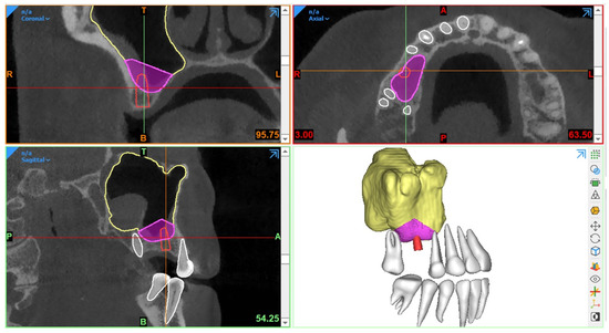
Figure 1. Example of graft volume estimation in Mimics (version 23.0, Materialise N.V., Leuven, Belgium) following automated sinus and teeth segmentation.
Traditionally, manual sinus segmentation, referred to as slice-by-slice delineation on 2D CBCT planes, performed by an expert is considered the gold standard. However, it is prone to certain limitations, such as labor-intensiveness, increased time consumption, and observer variability [91,92]. Based on the aforementioned limitations, semi-automated segmentation via thresholding-based approaches has been widely adopted for the segmentation of CBCT images to improve the efficiency of planning workflows [93,94]. Nevertheless, the final segmentation lacks optimal delineation due to the presence of different structural densities, and manual post-processing is often required. Recently, artificial intelligence (AI) in the form of deep learning has been employed for automated segmentation to overcome the limitations associated with both manual and semi-automated segmentation approaches. In deep learning, convolutional neural networks (CNNs) have demonstrated excellent performance with the employment of multi-layer neural computational connections for sinus segmentation on CBCT images [95,96,97]. The application of such deep learning-based approaches might enhance the quality and predictability of presurgical graft planning, enable a more precise treatment planning process and volumetric quantification of sinus/graft changes, and may further improve the standard of care. Yet, a lack of evidence exists related to the application of AI in the SFE treatment planning workflows.
2.2. Surgical Guidance
In SFE procedures, CBCT-based guidance has played a vital role in improving the precision of the surgical procedure with a reduction in complications. The guidance can be static or dynamic in nature. The procedures performed via these guides are referred to as “guided sinus lift [98]” or “guided bone grafting [99]”.
2.2.1. Static Surgical Guides
Static guides are designed via 3D planning software programs following the integration of intraoral scanned images with CBCT datasets and later fabricated using 3D printers. Such surgical templates act as a support aid and offer the advantages of time-efficiency, better working ergonomics, less operator stress, and greater predictability of the procedure [98,100,101]. Moreover, this procedure can also be combined with concurrent implant placement planning.
In 2008, Manderales and Rosenfeld [99] pioneered computer-guided SFE. They proposed using CAD/CAM surgical cutting guides for exact lateral wall outlining to considerably improve the quality and outcomes of the SFE procedure. Cecchetti et al. [98] have recently introduced virtual planning of surgical guides for lateral wall sinus elevation, concluding that the surgical template should be seen as a support aid to minimize risk and complications of the surgical procedures, especially in “difficult” cases.
Following the same concept, Osman et al. [102] and Strbac et al. [101] performed computer-guided SFE through a lateral window approach in addition to simultaneous implant placement. They found that applying static guides resulted in better and more consistent results. Similarly, Pistilli et al. [100] also concluded that such a digital approach is highly efficient in the mid-term (follow-up of 10 years) to implant rehabilitation of severely resorbed maxilla simultaneously with sinus lift.
Considering transrectal sinus augmentation, Pozzi et al. [103] and An et al. [104] combined static guide-based flapless maxillary crestal sinus augmentation with an immediate nonfunctional loading of dental implants, reporting a 98.53% and 100% survival rate at 3 years and 37 months, respectively.
Another type of surgical guidance is dynamic navigation, which is based on computer-guided surgery planning. Here, a physical surgical guide is unnecessary [105].
2.2.2. Dynamic Surgical Guides
A dynamic navigation system combined with CBCT imaging has been proposed for improving the intraoperative precision of implant placement, where a static surgical guide is not required and the operator can place the implants with real-time navigation [106]. With regard to SFE, limited evidence exists related to the application of navigation-based approaches. Recently, dynamic navigation has been used for posterior maxilla implant surgery via transcrestal SFE using piezoelectric devices [107]. The proposed technique offered high precision with excellent clinical outcome. However, it is recommended to perform further clinical studies to assess the effectiveness of dynamic navigation for performing SFE.
Considering the intraoperative use of CBCT imaging, Blake et al. [108] performed one case trial of using a C-arm-based CBCT scanner during sinus augmentation surgery under general anesthesia with iliac crest grafting. The images were taken prior to wound closure to immediately verify the surgery result. However, there is no solid evidence regarding such procedures for surgeries performed under local anesthesia.
3. Use of CBCT for Monitoring and Follow-Up after SFE
Post-surgical radiographic examination is vital [19,49,109,110,111,112,113,114,115,116,117,118,119,120,121] for the evaluation of bony integration of the inserted graft, follow-up of its long term stability, and also assessment of implant success and/or osteointegration after sinus lift procedures.
Ideally, imaging guidelines for the follow-up of sinus augmentation with or without immediate implant placement should follow the same regulations as those for post-surgical implant placement. Based on the AAOMR recommendations [55] and the guidelines for the use of diagnostic imaging in implant dentistry published by the E.A.O. [56], intraoral periapical radiography should be performed for the postoperative assessment of implants in the absence of clinical signs or symptoms. Panoramic radiographs may be indicated for more extensive implant therapy cases.
Meanwhile, CBCT [109,112,115] has become the standard imaging technique for 3D visualization and improved assessment prior to implant placement in the case of staged sinus augmentation. CBCT imaging can help to assess bone healing by visualizing how the material has integrated with the surrounding bone as well as if any signs of early resorption exist. It is beneficial in providing information about the volume, extent, and density of the augmented region [56] and can also be used to monitor any complications, which are not visible to the naked eye, such as mucosal changes, infection, and/or inflammation.
Furthermore, bone graft materials undergo remodeling over time at varying rates depending on the material used (resorbable versus non-resorbable) [122], and positive pressure formed inside the sinus during respiration also accelerates graft resorption [123]. Certainly, this remodeling could have a significant impact on the success of SFE outcome and the respective implant treatment. Thereby, CBCT can aid in the quantification of the resorption rate of different grafting materials [124,125,126] and also to monitor sinus changes at follow-up stages by comparing pre-surgical and/or post-surgical scans acquired at different time points. Usually, the Schneiderian membrane exhibits significant post-surgical edema, which increases the mucosal thickness visible. In addition, the edema might cause ostium obstruction with the possibility of impaired drainage capacity of sinus mucus. The reduction in the patency and obstruction of the ostium and infundibulum can lead to an inflammatory reaction and/or infectious processes of the sinus cavity, causing acute or chronic sinusitis [127]. Hence, CBCT imaging could act as a useful follow-up assessment tool to measure the thickness of the membrane and monitor mucosal changes in an attempt to avoid both early and delayed postoperative complications [128]. Additionally, following up the mucosal thickness changes could help to study the possible effects of different graft materials on sinus mucosa for research purposes [129].
It should be kept in mind that the use of CBCT should not be opted for regular follow-up assessment of normal SFE procedures without any evident or suspected complications to avoid exposure to unnecessary radiation doses. Postoperative CBCT could be indicated in cases with complications and contraindicated in patients where no direct benefit is to be expected. In instances of no clinical signs or symptoms of treatment failure or complications, periapical or panoramic images could be considered more than enough for postoperative follow-up. Moreover, CBCT imaging should also be justifiable for ethically approved clinical research projects, which might improve the standard of patient care. However, optimized strategies still need to be developed for SFE follow-up assessment, allowing good image quality and accurate 3D modeling with low-dose scanning protocols.
This entry is adapted from the peer-reviewed paper 10.3390/diagnostics13101684
This entry is offline, you can click here to edit this entry!