You're using an outdated browser. Please upgrade to a modern browser for the best experience.
Please note this is a comparison between Version 1 by Pankaj Dadheech and Version 2 by Sirius Huang.
Distributed Power Generation and Energy Storage Systems (DPG-ESSs) are crucial to securing a local energy source. Both entities could enhance the operation of Smart Grids (SGs) by reducing Power Loss (PL), maintaining the voltage profile, and increasing Renewable Energy (RE) as a clean alternative to fossil fuel. However, determining the optimum size and location of different methodologies of DPG-ESS in the SG is essential to obtaining the most benefits and avoiding any negative impacts such as Quality of Power (QoP) and voltage fluctuation issues.
- Distributed Power Generation
- Energy Storage System
- renewable energy
- Smart Grid
- soft computing
1. Introduction
Modern power systems have been transitioning from conventional centralized models into more decentralized grids that take advantage of Renewable Energy (RE) sources and Energy Storage Systems (ESSs) [1]. The intrinsic and variable nature of the RE sources influences the power network’s unwavering quality because of the abundant age of energy at some other point [2]. When researching planning [3] and Distributed Power Generation (DPG) operational segments, there are many critical challenges to consider. The existence of DPG demands the definition of multiple variables, including the optimization technology to be used, the capacity of units, the optimal placement, and the network connection. Power Loss (PL), voltage profile, stability, and reliability are accurately studied about DPG. As DPG penetration increases, system developers benefit from an optimization method to demonstrate the optimal solution for a given DN.
Today, ESS is critical for increasing power network stability and security [4]. For example, many ESSs are used in electric loops [5], such as the Pumped Type Hydro Energy Storage System (PTHSS), Compressed Air Energy Storage System (CAESS), Battery Energy Storage System (BESS), Super-Capacitor Energy Storage System (SCESS), Superconducting Magnetic Energy Storage System (SMESS), and Flywheel Energy Storage System (FESS). Many technologies are combined to create a hybrid power system, as shown in Figure 1.
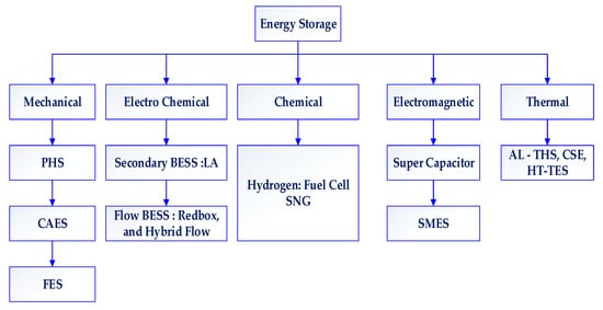
Figure 1.
The hierarchical flow of energy storage systems.
2. Distribution Network Planning with DPG and ESS
Multiple units and a connected network are required for centralized Power Generation (PG) systems to produce enough energy. Power is transmitted through these systems and provided to residential, commercial, and industrial consumers. Decentralized DPG topology is used to link these generators to the DN. Decentralized energy distribution stations are positioned closer to users and supply electricity to local areas without using large-scale energy facilities. Decentralized energy grids, as opposed to large-scale conventional utility plants, can transfer, store, and harvest electricity or heat in smaller units closer to customers. A decentralized system will be refreshed in a few decades because the power generation of fossil resources is demanding because of high capital costs, infrastructure costs, volatile losses, the depletion of non-renewable sources, and ecosystem impacts. Thus, DNs with high RE generator penetration has become more popular. Depending on the country and utility provider, they have different interpretations. Due to its low impact on the SG, DPG is referred to as “approved for bus connections,” “DN linked at a distribution voltage level,” or “from a few kW to 50 MW,” among other identities. US power stations have recommended a new DPG advanced technologies and application benchmark. Thus, DPG could be identified by connection point, power, and technology type, as shown in Figure 2.
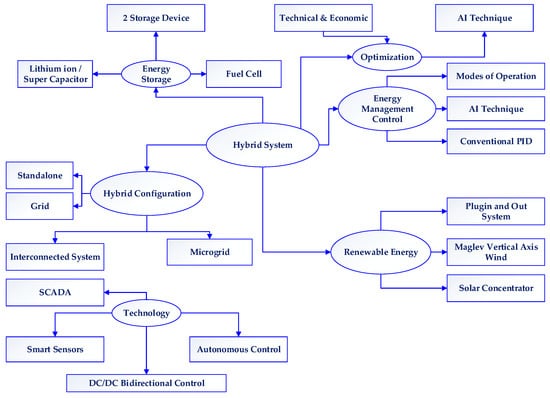
Figure 2.
Constructional architecture of yybrid RE-DPG with ESS.
The location of electricity generation and project scale are the primary distinctions between centralized and dispersed generation. Although the two types coexist in the same system, centralized DPG differs significantly. In the centralized method, more extensive facilities concentrate energy production and supply it to consumers who may be kilometers away. In the case of DPG, smaller units produce power close to or at the point of consumption. It uses various RE sources, including solar, wind, hydro, and biogas. The voltage, phase angle, and frequency of DPG sources in SGs must match. Instability within an organization caused by input mismatches can harm profit and loss. The SG powers its connected area in the microgrid even if the primary power supply from PG inputs falls due to a fault or redundant circumstance. The capacity of SG PS is limited, and may not be able to support peak consumer load.
In this case, the optimal location and size of the DPG are critical for supplying uninterrupted power to end users. Energy can move both ways in the microgrid, in any case. Both protective relays are turned on when the effectiveness operator continues distribution lines. To maximize its effectiveness, SG uses a broad range of resources. The SG’s reliability and stability depend on the DPG’s placement. Location identification is more challenging and unpredictable in mesh and connected networks because of the lack of model factors. Electrical energy is stored as heat, electrochemical, electromagnetic, mechanical, and electrochemical energy. The following are some of the implications of an ESS in practical applications: (1) It is suitable for high-power and high-energy applications; (2) It is possible to integrate it into existing power plants; (3) Its installation is simple. With continued acceptance and availability, the cost of batteries falls. Capital cost, power and energy efficiency, rotational speed, performance, low latency, self-release downsides, and workflow lifetime are some of the ESS features required in various situations. This section briefly discusses some ESSs used for combined wind control. Artificial Intelligence (AI)-based ESS for REs is detected at all stages.
2.1. Distribution Network Expansion Planning with DPG Sources
A highly infiltrated RE combined with a low-cost ESS could reduce the unpredictability and flexibility issues that plague electrical networks. In SGs, ESS is required to balance the discrepancy between RE generators, improve them, and save excess energy from renewable hot spots for subsequent use in non-generation or low energy consumption. Many systems have recently been made to explore the possibility of designing an ESS with REs. Photovoltaics (PV) is one of the quickest sustainable RE sources to build up comprehensively, with the ultimate objective being to make nature free from carbon outflows and make it more feasible. It is conceivable, considering the safety measures that managerial frameworks around the globe have taken. One-day PV advancement is demonstrating more productivity and pragmatism at a moderate expense. However, insignificant working expenses, zero discharge, and consistently declining DPG costs make it an accurate pattern for expansion plans in DPG capacity. The solar PV generation schematic structure is shown in Figure 3.
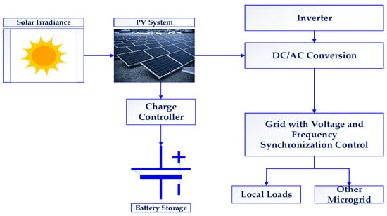
Figure 3.
Schematic diagram of a DPG-ESS unit.
The effects of PV energy on the different candidate units were discussed [6][13]. In general, the mode of operation of a PV system can be in a grid, off-grid, or hybrid manner. The PS network distributes power from the PV system in “on-grid mode.” In “off-grid” mode, the PV system only powers the house, not the PS. In the hybrid PS function, the PV powers homes and the power distributor during off-peak hours. PV energy is DC. Thus, inverter topologies must convert DC to AC for end users. Centralized [7][14], string, and multi-string inverters have significantly increased wind turbine limits and costs. Energy costs dropped by 15% [8][15].
In order to plan new generation units that meet technical and economic constraints, Generation Expansion Planning (GEP) is the best option. GEP is challenging due to the generation unit’s size, duration, and nonlinearity. Due to a lack of knowledge, businesses are forced to deal with this issue in a hazardous atmosphere because the competition among generational companies to maximize their profits forces them to conceal their tactics. Different nonlinear solutions have been presented to address this complex problem in an unclear context. The techniques include game theory, a two-level game model, a multi-agent system, a genetic algorithm, and particle swarm optimization. The GEP issue looks at the game plan of ideal choice vectors over an arranged skyline that decreases speculation and operational costs under fitting obstacles. The general issue with integrating DPG into existing networks is that DN is a passive network that transfers power unidirectionally from the centrally generated high voltage (HV) level to loads at the medium voltage (MV) and low voltage (LV) levels. Unit-wise issues have been connected with control theory decisions. It is confined to the measure of adventure and operational expenses. The resulting Consolidated-Unit-Commitment and Capacity Expansion (C-UC-CE) model is a high-dimensional Mixed Integer Linear Programming (MILP). By then, the model of age advancement is nitty-gritty [9][10][16,17].
The control of dynamical systems in designed equipment and processes is the subject of control theory. A model or algorithm must manage the system inputs to ensure control stability, minimize delay, achieve proportional gain, and maintain stable error. It is conducted so that performance is optimized.
2.1.1. Generation Expansion Model
Except for data transfer restrictions, the bus-bar framework model considers future choices, such as the desired units to produce annually, the estimation in a given period, and the entire team. This decision-making is accepted by central facilitators [11][18]. In order to obtain additional objectives, it might be helpful to illustrate optional methodologies and real-world designs. The operational costs of warm generators are less.
The investment cost in year ‘x’ ( ) is represented in Equation (1),
where NG denotes the generator entities,
IGl,g is an additional unit of a generator, and is the generator cost of generator ‘g’ in year ‘x’ [USD/MW].
In the above instance, the annual operating cost is connected to Equation (2).
where COx is the operating cost,
CUD is the unit span cost [USD/MWh],
is the variable cost of generator ‘g’ in year ‘x,’
is the PS provided by ‘g’ at hour ‘t’ in year ‘x’ [MW],
is the investment cost of generator ‘g’ [USD] and is the load shedding at hour ‘t’ in year ‘x’ [MW] [12][19].
2.1.2. Demand Constraints
During the planning hour and the crucial PG program, the development of all DPG entities is combined into many systems. As a result, interest rates are determined based solely on the output of these DPG plants, disregarding the producers of the special regimes depicted in Equation (3),
whereas D(X) denotes the interest projection rate in the specific hours (h) to prepare for time (t) and trimester tri (MWh). The term SRP refers to a single regime producer. All power plants, excluding siphoning plants, follow the “Npump” method, and all pumping power plants are arranged according to the pump technique.
Considering the above investigation work by the decision-makers, the ongoing portions are typical in the model appraisal. Furthermore, in the GEP, two types of plants have been considered to introduce the structures, such as Solar Plants with Storage Capacity (SPWS) and the other that does not have storage capacity (i.e.,) Solar Plants with Non-Storage Capacity (SPWNS). The Forged Outage Rate (FOR) has been perceived as 76% for and 6% for SPWS. Each plant is divided into high-emission and low-emission plants, and the primary sources are High Emission Plants (HEP)-Coal, Oil, Low Emission Plants (LEP)-Solar, and Nuclear plants. The GEP shows appraisals made at four levels out of solicitations. The two definite cases are envisioned with the inclusion of sunlight-based plants, either as an exchange for oil plants or as an elective hypothesis in the second level [13][20]. The third level determines whether or not sunlight-based plants must limit their cut-off. Similarly, in the fourth level, affectability review on the system’s GEP for various blends of cut-off spotlights on daylight-based entryways (5–10%/10–20% of the total), treatment and discipline costs for discharges from HEP and FOR acknowledged SPWNS and SPWS, for six and 14-year masterminding horizons. A schematic outline of the case appraisals is depicted in Figure 4.
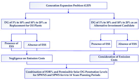
Figure 4.
Case analysis for GEP.
2.2. Distribution Network Expansion Planning with ESS
Distribution Expansion Planning (DEP) aims to reduce the computation weight of the issue. Nevertheless, this could jeopardize DEP’s game plans’ accuracy, particularly in tremendous scope control systems, where power may stream over significant distances. The term “responsibility” refers to the act of determining whether or not a person is responsible for their actions. It has consistently achieved a higher number of line speculations. However, it has compressed the effects of setbacks on ideal transmission advancement [14][21].
2.2.1. System Modeling
The limitations placed on ESS have been damaged, which now contribute significantly to voltage stability and power flow balancing [15][22]. Five primary factors need to be considered while deploying Storage Devices (SDs): total capacity in terms of power and energy, charge-discharge rate of efficiency (η), self-discharging rate, and State-Of-Charge (SOC). The ESS constraints and parameters are modeled as follows.
The charging cycle is assumed in Equation (4)
The process of discharging is given in Equation (5)
where Δtη and Δt are the charging rates of SD and discharge rate, respectively. ‘Pd’ and ‘Pc’ are the discharging and charging capacity of SD in terms of power, and ‘η’ is its exact efficiency.
where Pt(t) is the power exchange between SG and SD, as given in Equation (6).
2.2.2. Storage Objective Functions
Due to their variant nature, RE resources disturb the QoP by introducing harmonics and transients into the power profile [16][23]. The appropriate use of ESSs can reduce these effects; however, some limitations are imposed on them, such as high configuration costs. So, the primary goals, such as minimizing PL [17][24] and other ESS operations, are maximized with a little investment cost. The overall objective can be represented as follows in Equation (7)
where OBJ is the objective. ‘n’ represents the entire number of buses in the PS, ‘pst’ is the price per energy from ESS, and q(t) is the unit energy cost at the current time ‘t’. The second term in the OBJ represents network losses, while Pti(t) represents the total volume of power supply at node ‘i’ and is expressed as follows in Equation (8),
Vi(t) represents the complex voltage at bus ‘i’, while Yik and Vik are the admittance and voltage levels between bus ‘i’ and ‘k’ respectively. Equations (9) and (10) express the power constraints at the respective buses.
where Pi and Qi are the total and reactive PL at bus i, θij is the phase difference profile between nodes, and Gij and Bij represent the corresponding conductance and susceptance of the power supply.
The negligence of the network issue of DEP is incorporated, disregarding the operational cost of moving impact. Thus, a lossless DEP achieves a system procedure with a lower development cost and higher framework disasters. DN deprivation permits adjusted development with limits on legal expenses [18][25]. The natural calamity points to different generations and additional inflows throughout the system. If disasters are unnoticed, congested lines may not appear to be embedded. Such sequences are excluded from the arrangement of the imaginary development choices. It is receiving the activation of an additional agreement. Network issues have a significant impact on generator dispatch solicitation. It consequently moves the framework’s progress game plan [19][26].
The recently referenced effects have been checked in two relevant investigations in the results territory. Generally, a DEP prompts a framework arrangement with lower general system costs. Thus, a trade-off has been refined between fragments with high prices. Some additional investments are completed to mitigate their negative consequences when misfortunes are acknowledged. The ideal control systems are studied to reduce disasters and improve energy output ranges.
2.3. DN Planning under Deterministic and Probabilistic Loading Conditions
Given the deterministic and probabilistic nature of load conditions, planning is conducted from two perspectives: the consumer and the market. Since demand response programs significantly reduce operational costs, the higher DPG penetration and the ESS landing are reinforced by an efficient solution. An incentive-based method has been presented to improve the operation factor. BESS is installed and fulfills the nominal frequency ranges [20][27]. Another heuristic methodology for optimal DPG formation arrangement has been developed [21][28]. It authorizes an acceptable level of reduction in PL. Resistance assessment is included without the monotonous computation of Optimal Power Flow (OPF) investigation. Its review is found to be direct. A dynamic system for DPG units’ ideal size and suitable hubs. Its measure is versatile, irrespective of any conditions.
Moreover, it depicts that the perfect territory for a DPG unit is to check its ideal size. Moreover, it improves voltage profiles [22][29] by reducing system obstacles. A reconfiguration methodology has been presented and recommended. It aims to disperse powers depending on the Power Supply Capacity Index (PSCI) to maintain security challenges because of the ascent in EV quantity with a space-based overall Active Distribution Network (ADN). Consequently, a widespread and natural design is formed to recover all-electric vehicle (EV) loads. After careful consideration, the PSCI ensures standard operating procedures for a terrible power stream with uneven development. Direct load control exists, but ESS has a flawless load prediction model. Peak load shifting could provide consumers with the most optimal energy schedule. There has been some fine-tuning observed. The performance of the heat transformer for retention is improved by vitality [23][30].
This method of intelligence relies on neural displaying to obtain a multi-variable limit. It improves the controlled and uncontrolled boundaries of the current system, as shown in Figure 5. As was mentioned in SectionSection 1 1 that ESS has many DN applications [24][31]. An actual ESS application for DN is its planning [25][32]. Most operations, whether load balancing or mediation, take the first application into account [26][33].
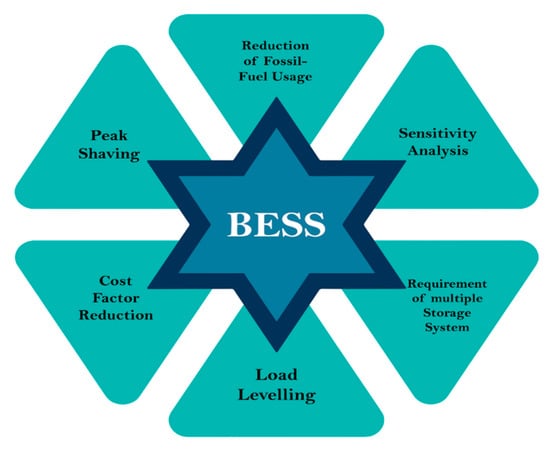
Figure 5.
Advantages rendered by BESS integration on DN.
Mediation maintains ESS when energy is low-cost. It balances the load during peak demand when electricity rates rise [27][34]. Thus, the load is distributed at a low cost throughout the service’s lifetime. As shown in Figure 6, the practice of relieving load or balancing is also known as vacuum filling or emission reduction. Energy to charge the ESS is provided by upstream networks (HV/MV stations) of traditional DN and other ADN sources during low-load times. Uncontrolled DPG is powered by renewable sources [28][35] and turned by small pumping resources. The charging and discharging rate in correspondence to time are demonstrated, while the real PS difference between DPG and load due to the charging and discharging of ESS is presented in Table 1. The optimization algorithm has adopted the YALMIP optimizer toolkit for ESS while validating the operational and investment costs. The charging and discharging behavior of SD, as well as its loading effects, have been thoroughly investigated.
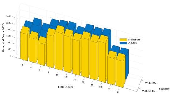
Figure 6.
Load leveling features in the presence and absence of ESS.
Table 1.
Energy exchange between an SG, ESS, and load.
| Time (h) |
Net Energy Exchange (MWh) |
ESS Status |
Generated SG Power (MW) |
Load (MW) |
|---|---|---|---|---|
| 1 | 4 | Charging | 279 | 264 |
| 2 | 4 | Charging | 279 | 264 |
| 3 | 4 | Charging | 279 | 264 |
| 4 | 4 | Charging | 279 | 264 |
| 5 | 0 | No action | 330 | 360 |
| 6 | 0 | No action | 330 | 360 |
| 7 | 0 | No action | 330 | 360 |
| 8 | 0 | No action | 330 | 360 |
| 9 | 5 | Discharging | 362 | 361 |
| 10 | 5 | Discharging | 362 | 361 |
| 11 | 5 | Discharging | 362 | 361 |
| 12 | 5 | Discharging | 362 | 361 |
| 13 | 5 | Charging | 385 | 361 |
| 14 | 5 | Charging | 385 | 361 |
| 15 | 5 | Charging | 385 | 361 |
| 16 | 5 | Charging | 385 | 361 |
| 17 | 5 | Discharging | 350 | 348 |
| 18 | 5 | Discharging | 350 | 348 |
| 19 | 5 | Discharging | 350 | 348 |
| 20 | 5 | Discharging | 350 | 348 |
| 21 | 2 | Charging | 310 | 300 |
| 22 | 2 | Charging | 310 | 300 |
| 23 | 2 | Charging | 310 | 300 |
