Your browser does not fully support modern features. Please upgrade for a smoother experience.
Please note this is a comparison between Version 2 by Camila Xu and Version 1 by Yanhong Peng.
In 1961, a theory relating to ionic wind was developed by Robinson, who proposed the possibility of developing functional electrostatic blowers, namely electrohydrodynamic (EHD) gas pumps.
- functional fluidic pumps
- electrohydrodynamic pumps
- flow delivery
- robotics
1. Brief History of the Electrohydrodynamic (EHD) Pump
Electrohydrodynamic (EHD) effects were first discovered in 1629 by Cabeo, who observed that electric fields could attract sawdust, after noticing repulsion following physical contact [1]. However, Cabeo did not understand the rationale behind this phenomenon. Over the next few hundred years, Wilson investigated the EHD effect, coining the term electric wind, and attempted to find practical applications [2]. In 1961, a theory relating to ionic wind was developed by Robinson, who proposed the possibility of developing functional electrostatic blowers, namely EHD gas pumps [3]. Although this electrostatic blower had the advantages of low wear, quiet operation, and no requirement for lubrication as compared to conventional fans (i.e., a mechanical pump), Robinson was disappointed by the inability to overcome the extremely low operating efficiency (the conversion efficiency was less than 1% from corona discharge to mechanical energy). The low conversion efficiency from electrical to mechanical energy represented a primary limitation of EHD pumps. Many researchers attempted to improve the device structure using EHD pumps, and there have been some experimental studies focused on improving the flow rate and efficiency of EHD pumps. In 2008, Moreau et al. made substantial improvements [4]. Morrow et al. increased the electrical energy conversion efficiency to 1.72% via the pin-ring and pin-grid electrode configuration, which provided more than twice the conversion efficiency compared to previous EHD effect studies. In recent times, the higher energy conversion efficiency of EHD pumps has also been demonstrated by June et al. [5]. June et al. experimentally tested a five-needle mesh-like EHD pump prototype and found static efficiencies of up to 14%.
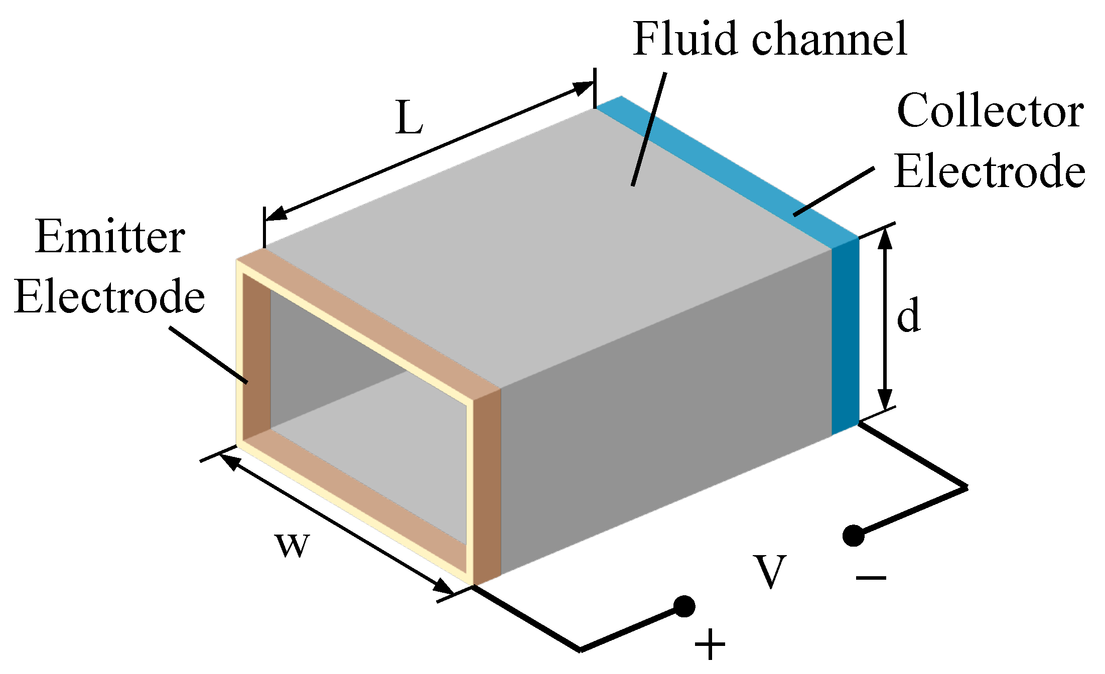
In addition to EHD air pumps, functional fluidic EHD pumps have also been developed in recent decades. Sharbaugh et al. [6] were the first to use media other than air in EHD pumps, attempting to apply EHD pumps to transformers. However, this was deemed impractical owing to subsequent contamination of the collector electrode after hundreds of hours of operation. Five-years later, Crowley et al. were the first researchers to publish an experimental study on the behavior of multiple working fluids using a rectangular EHD pump with a parallel strip-to-strip electrode [7]. This paperntry develops a basic EHD pumping model to illustrate the working fluid’s material properties. They applied the model to several experimental pumps reported earlier and found good agreement. Examples of this model demonstrate several new fluids suitable for EHD pumping. The authorsresearcher concluded that there are considerable differences in the maximum velocity that can be achieved for different fluids and that the maximum velocity for a given fluid cannot determine the maximum efficiency. The basic geometry of a functional fluidic EHD pump is depicted in Figure 1. Several years later, a multi-stage EHD pump using transformer oil as the working fluid was designed as a practical solution for motor cooling [8,9][8][9]. There are also studies using a dielectric fluid (dibutyl sebacate, an organic plasticizer) as a medium, both as a single-stage and a multi-stage configuration of the same geometry. Researchers in other studies also employed a dielectric fluid (such as dibutyl sebacate) as a medium, both as single- and multi-stage configurations of the same geometry [10,11][10][11].

Figure 1. Fluid EHD pump geometry [7]. L, d and w represent channel length, depth and width, respectively. V denotes the high-voltage power source.
Despite the computational conditions, the flawed theories of physics and materials science, and the limitations of experimental equipment, previous explorations built the foundation for future research, as these results retain the majority of their validity even today.
2. Pump Structure and Material
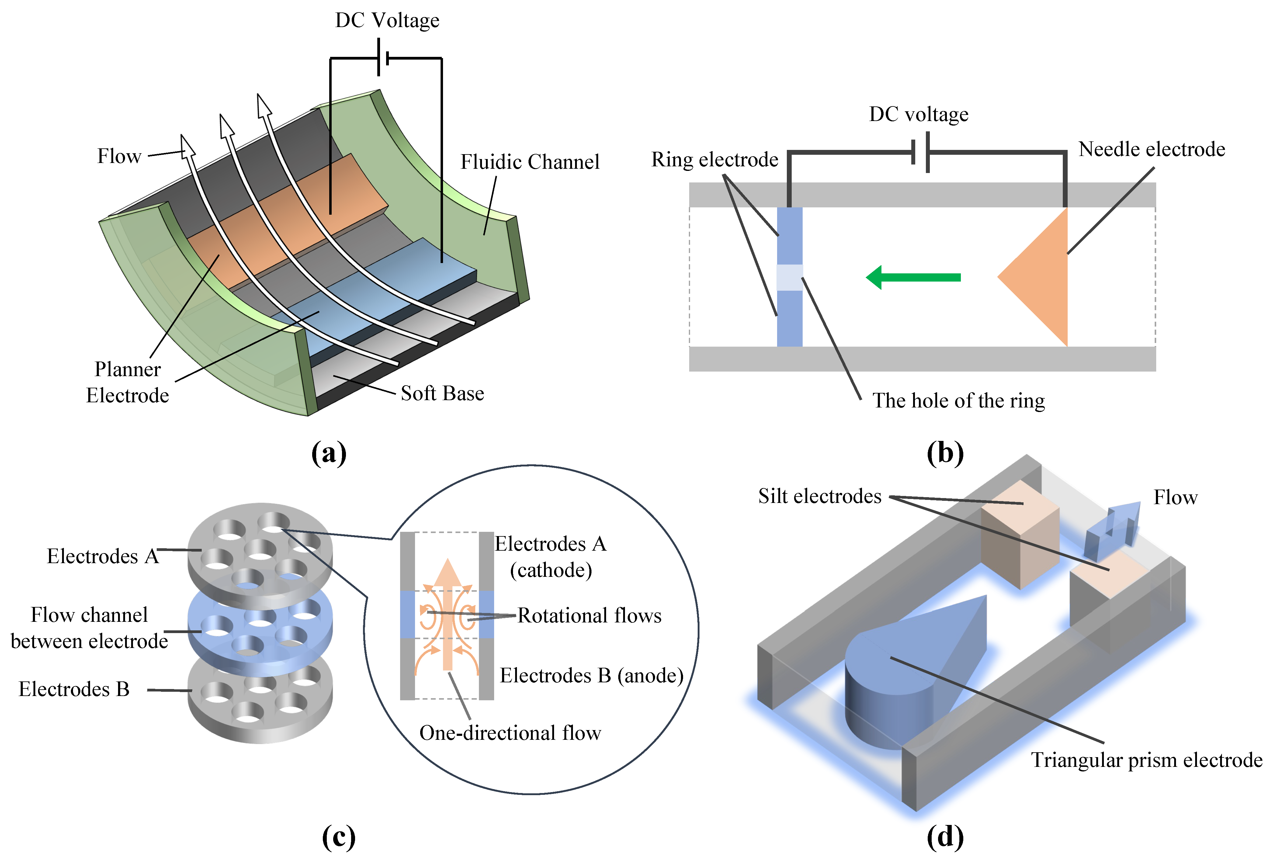
This section introduces the EHD functional fluidic and gas pump’s base, electrode material, and geometry selection. Currently, there are many EHD pump electrode geometries, such as needle, ring, planar, wire, mesh, and disk. These electrodes can form five basic electrode pairs in functional fluidic EHD pumps: thin planar electrode pairs, needle-to-ring electrode pairs, disk electrode pairs, triangular prism-to-silt electrodes (TPSE), and helical electrodes. Schematics of some electrode pairs are shown in Figure 42. Thin planar electrode pairs bear a low power density of 6.3 Wm/cm22[48][12] while needle-to-ring electrode pairs and TPSE are 111 Wm/cm22[49][13] and 17.5 Wm/cm22 [50][14]. Thin planar electrodes and TPSE generally use photomask patterning, which is easy to reproduce; however, needle ring electrodes are mainly assembled manually, with low reproducibility [51][15]. Moreover, thin planar electrodes and TPSE are fabricated with batches and are easy to integrate. However, needle ring electrodes are individually manufactured and hard to integrate.

References
- Cabeo, N. Philosophia Magnetica; Apud F. Succium: Ferrara, Italy, 1629.
- Wilson, B. A Treatise on Electricity: The Second Edition. By Benjamin Wilson, F.R.S; Printed and sold by C. Davis in Holbourn, and R. Dodsley in Pallmall: London, UK, 1752.
- Robinson, M. Movement of air in the electric wind of the corona discharge. Trans. Am. Inst. Electr. Eng. Part I Commun. Electron. 1961, 80, 143–150.
- Moreau, E.; Touchard, G. Enhancing the mechanical efficiency of electric wind in corona discharges. J. Electrost. 2008, 66, 39–44.
- June, M.S.; Kribs, J.; Lyons, K.M. Measuring efficiency of positive and negative ionic wind devices for comparison to fans and blowers. J. Electrost. 2011, 69, 345–350.
- Sharbaugh, A.H.; Walker, G.W. The design and evaluation of an ion-drag dielectric pump to enhance cooling in a small oil-filled transformer. IEEE Trans. Ind. Appl. 1985, IA-21, 950–955.
- Crowley, J.M.; Wright, G.S.; Chato, J.C. Selecting a working fluid to increase the efficiency and flow rate of an EHD pump. IEEE Trans. Ind. Appl. 1990, 26, 42–49.
- Bologa, M.; Kozhevnikov, I.; Kozhukhari, I. Multistage electrohydrodynamical pump. In Proceedings of the 2000 Annual Report Conference on Electrical Insulation and Dielectric Phenomena (Cat. No. 00CH37132), Victoria, BC, Canada, 15–18 October 2000; IEEE: Piscataway, NJ, USA, 2000; Volume 1, pp. 57–60.
- Kojevnikov, I.; Motorin, O.; Bologa, M.; Kojevnikova, A. Optimization of the electrohydrodynamic pump. In Proceedings of the Annual Report Conference on Electrical Insulation and Dielectric Phenomena, Cancun, Mexico, 20–24 October 2002; IEEE: Piscataway, NJ, USA, 2002; pp. 204–207.
- Kano, I.; Mizuochi, K.; Takahashi, I. Micro-electrohydrodynamic pump by dielectric fluid: Improvement for performance of pressure using cylindrical electrodes. In Proceedings of the JFPS International Symposium on Fluid Power, Tsukuba, Japan, 7–10 November 2005; The Japan Fluid Power System Society: Tokyo, Japan, 2005; Volume 2005, pp. 575–579.
- Kano, I.; Takahashi, I. Improvement for pressure performance of micro-EHD pump with an arrangement of thin cylindrical electrodes. JSME Int. J. Ser. B Fluids Therm. Eng. 2006, 49, 748–754.
- Yokota, S. High-integration micromotor using electro-conjugate fluid (ECF). J. Robot. Mechatron. 2005, 17, 142–148.
- Raghavan, R.V.; Qin, J.; Yeo, L.Y.; Friend, J.R.; Takemura, K.; Yokota, S.; Edamura, K. Electrokinetic actuation of low conductivity dielectric liquids. Sens. Actuators B Chem. 2009, 140, 287–294.
- Seo, W.S.; Yoshida, K.; Yokota, S.; Edamura, K. A high performance planar pump using electro-conjugate fluid with improved electrode patterns. Sens. Actuators A Phys. 2007, 134, 606–614.
- Kim, J.w.; Yamada, Y.; Yokota, S. Micro ECF (electro-conjugate fluid) hydraulic power sources based on the modular design of TPSEs (triangular prism and slit electrode pairs). Int. J. Adv. Manuf. Technol. 2020, 106, 627–639.
- Mao, Z.; Iizuka, T.; Maeda, S. Bidirectional electrohydrodynamic pump with high symmetrical performance and its application to a tube actuator. Sens. Actuators A Phys. 2021, 332, 113168.
- Mao, Z.; Nagaoka, T.; Yokota, S.; Kim, J.w. Soft fiber-reinforced bending finger with three chambers actuated by ECF (electro-conjugate fluid) pumps. Sens. Actuators A Phys. 2020, 310, 112034.
- Tsukiji, T.; Hamada, K.; Shimizu, T. A Pump using EHD Fluid. JFPS Int. J. Fluid Power Syst. 2019, 11, 43–48.
- Mao, Z.; Yoshida, K.; Kim, J.w. Developing O/O (oil-in-oil) droplet generators on a chip by using ECF (electro-conjugate fluid) micropumps. Sens. Actuators B Chem. 2019, 296, 126669.
- Mao, Z.; Yoshida, K.; Kim, J.w. Active sorting of droplets by using an ECF (Electro-conjugate Fluid) micropump. Sens. Actuators A Phys. 2020, 303, 111702.
- Mao, Z.; Yoshida, K.; Kim, J.w. A droplet-generator-on-a-chip actuated by ECF (electro-conjugate fluid) micropumps. Microfluid. Nanofluid. 2019, 23, 1–12.
- Kano, I.; Nishina, T. Effect of electrode arrangements on EHD conduction pumping. IEEE Trans. Ind. Appl. 2013, 49, 679–684.
- Yu, H.; Yu, J.; Ma, C. Design, fabrication and experimental research for an electrohydrodynamic micropump. Sci. China Technol. Sci. 2010, 53, 2839–2845.
- Mao, Z.; Yoshida, K.; Kim, J.w. Releasing large-area SU-8 structures without using any sacrificial layers. Microelectron. Eng. 2019, 212, 53–60.
- Cacucciolo, V.; Shintake, J.; Kuwajima, Y.; Maeda, S.; Floreano, D.; Shea, H. Stretchable pumps for soft machines. Nature 2019, 572, 516–519.
- Le, N.; Labbe, J. Corrosion by corona discharges: Determination of corrosion products by vibrational spectroscopy. In Proceedings of the 13th Meeting of the Franco-British Group on Electrical Discharges, Glasgow, UK; 1983.
- Mao, Z.; Yoshida, K.; Kim, J.w. Fast packaging by a partially-crosslinked SU-8 adhesive tape for microfluidic sensors and actuators. Sens. Actuators A Phys. 2019, 289, 77–86.
- Noll, C.G.; Lawless, P.A. Comparison of germanium and silicon needles as emitter electrodes for air ionizers. J. Electrost. 1998, 44, 221–238.
- El-Bahy, M.M.; Abou El-Ata, M.A. Onset voltage of negative corona on dielectric-coated electrodes in air. J. Phys. D Appl. Phys. 2005, 38, 3403.
- Rickard, M.; Dunn-Rankin, D.; Weinberg, F.; Carleton, F. Maximizing ion-driven gas flows. J. Electrost. 2006, 64, 368–376.
- Takeuchi, N.; Yasuoka, K.; Chang, J.S. Wire-rod type electrohydrodynamic gas pumps with and without insulation cover over corona wire. IEEE Trans. Dielectr. Electr. Insul. 2011, 18, 801–808.
- Moreau, E.; Audier, P.; Benard, N. Ionic wind produced by positive and negative corona discharges in air. J. Electrost. 2018, 93, 85–96.
- Zhang, J.; Lai, F. Effect of emitting electrode number on the performance of EHD gas pump in a rectangular channel. J. Electrost. 2011, 69, 486–493.
- Chang, Y.; Peng, J.; Lin, S.; Lai, F. Flow induced by an EHD gas pump with secondary emitting electrodes. J. Electrost. 2020, 105, 103438.
- Ramadhan, A.A.; Kapur, N.; Summers, J.; Thompson, H. Numerical development of EHD cooling systems for laptop applications. Appl. Therm. Eng. 2018, 139, 144–156.
- Fylladitakis, E.D.; Moronis, A.X.; Kiousis, K.N. Experimental evaluation of a needle-to-grid EHD pump prototype for semiconductor cooling applications. Int. J. Circuits Syst. Signal Process 2014, 8, 337–342.
- Fylladitakis, E.D.; Moronis, A.X.; Kiousis, K. Design of a prototype EHD air pump for electronic chip cooling applications. Plasma Sci. Technol. 2014, 16, 491.
- Kim, C.; Park, D.; Noh, K.; Hwang, J. Velocity and energy conversion efficiency characteristics of ionic wind generator in a multistage configuration. J. Electrost. 2010, 68, 36–41.
- Qiu, W.; Xia, L.; Tan, X.; Yang, L. The velocity characteristics of a serial-staged EHD gas pump in air. IEEE Trans. Plasma Sci. 2010, 38, 2848–2853.
- Birhane, Y.; Lin, S.; Lai, F. Flow characteristics of a single stage EHD gas pump in circular tube. J. Electrost. 2015, 76, 8–17.
- Birhane, Y.T.; Lin, S.C.; Lai, F.C. Flow characteristics of a two-stage EHD gas pump in a circular pipe. IEEE Trans. Ind. Appl. 2017, 53, 2461–2470.
More
