Finned tube heat exchangers are used in many technological applications in both civil and industrial sectors. Their large-scale use requires a design aimed at reaching high thermal efficiency as well as avoiding unnecessary waste of resources in terms of time and costs.
Multi-scale methods are very flexible and suitable for different heat exchanger geometries and working conditions because they integrate analytical methods’ benefits with more accurate numerical approaches.
The hybrid method is an alternative design procedure based on an algorithm that uses a multi-scale method, based on data from either analytical, numerical, or experimental investigations.
- heat exchanger
- design
- model
- optimization
- hybrid method
1. Introduction

2. Heat Exchanger Design Procedure

3. Multi-sScale mModels: the hThe Hybrid mMethod
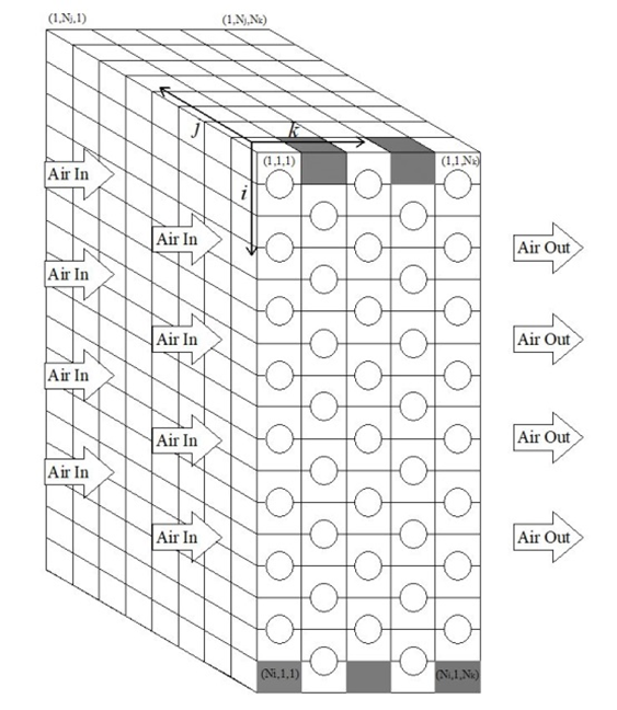
Multi-scale models are very flexible and suitable for different HX geometries and working conditions because they integrate analytical methods’ benefits with more accurate numerical approaches. The hybrid method is an alternative design procedure developed by Starace et al. [11] and based on an algorithm that uses a multi-scale method, based on data from either analytical, numerical, or experimental investigations. The hybrid approach was originally used on compact cross-flow HXs, where the entire geometry was split into a number of control volumes. Through the application of a regression technique, Carluccio et al.’s [12] thermo-fluid dynamics simulation findings on the two finned surfaces of the HXs were used to develop the prediction functions of heat transfer, extending the local results over the whole geometry of the HX. By starting with small-scale experimental tests, Fiorentino and Starace [13] developed another application of the hybrid technique for countercurrent evaporative condensers to assess their performance. Results indicate that, when compared to experimental tests, the method is accurate and can determine the air temperature and relative humidity at the output with errors of 2.5% and 4%, respectively. Starace et al. [14] employed this technique on a plate-finned evaporator with a basic refrigerant circuit configuration, using the control volume approach (Figure 4).

Figure 4.
The scheme of the HX’s geometry through a three-dimensional matrix [14].
Then, Starace et al. [15] achieved progress in the development of the hybrid technique by using it on evaporators with complex circuit layouts to assess the impact of circuitry configuration on overall performance in terms of heat transfer rate and refrigerant pressure drops. Then, additional tests were conducted while taking into account various refrigerants and changing the fluid conditions at the input [16]. Finally, the hybrid approach algorithm underwent additional modifications to make it even more adaptable and compatible with predictions of the performance of real heat exchangers [17]. Other tests were conducted by adjusting the operating conditions, such as the temperature gradient between refrigerant and air at the inlet and the air relative humidity.
References
[1] Bergman, A.A.; Incropera, F.P. Fundamentals of Heat and Mass Transfer; John Wiley & Sons: Hoboken, NJ, USA, 2011.
[2] Rohsenow, W.M.; Hartnett, J.P.; Cho, Y.I. Handbook of Heat Transfer, 3rd ed.; McGraw-Hill: New York, NY, USA, 1998.
[3] Tahseen Ahmad Tahseen; Ishak, M.; Rahman, M.M. An overview on thermal and fluid flow characteristics in a plain plate finned and un-finned tube banks heat exchanger. Renew. Sustain. Energy Rev. 2015, 43, 363–380.
[4] Basavarajappa, S.; Manavendra, G.; Prakash, S.B. A review on performance study of finned tube heat exchanger. J. Phys. Conf. Ser. 2020, 1473, 012030.
[5] Kakac, S.; Liu, H. Heat Exchangers: Selection, Rating and Thermal Design, 2rd ed.; CRC Press: Boca Raton, FL, USA, 2002.
[6] Hesselgreaves, J.E.; Law, R.; Reay, D. Compact Heat Exchangers: Selection, Design and Operation, 2nd ed.; Butterworth-Heinemann, 2016.
[7] Zohuri, B. Compact Heat Exchangers, 1st ed.; Springer: Cham, Switzerland, 2017.
[8] Klemes, J.J.; Arsenyeva, O.; Kapustenko, P.; Tovazhnyanskyy, L. Compact Heat Exchangers for Energy Transfer Intensification: Low Grade Heat and Fouling Mitigation, 1st ed.; CRC Press: Boca Raton, FL, USA, 2015.
[9] Wang, C.-C.; Hwang, Y.-M.; Lin, Y.-T. Empirical correlations for heat transfer and flow friction characteristics of herringbone wavy fin-and-tube heat exchangers. Int. J. Refrig. 2002, 25, 673–680.
[10] Shah, R.K.; Sekulic, D.P. Fundamentals of Heat Exchanger Design; John Wiley & Sons: Hoboken, NJ, USA, 2003.
[11] Starace, G.; Fiorentino, M.; Longo, M.P.; Carluccio, E. A hybrid method for the cross flow compact heat exchangers design. Appl. Therm. Eng. 2017, 111, 1129–1142.
[12] Carluccio, E.; Starace, G.; Ficarella, A.; Laforgia, D.; Numerical analysis of a cross-flow compact heat exchanger for vehicle applications. Appl. Therm. Eng. 2005, 25, 1995–2013.
[13] Fiorentino, M.; Starace, G. The design of countercurrent evaporative condensers with the hybrid method. Appl. Therm. Eng. 2018, 130, 889–898.
[14] Starace, G.; Fiorentino, M.; Meleleo, B.; Risolo, C. The hybrid method applied to the plate-finned tube evaporator geometry. Int. J. Refrig. 2018, 88, 67–77.
[15] Starace, G.; Macchitella, S.; Fiorentino, M.; Colangelo, G. Influence of circuit arrangement on evaporator performance using the hybrid method. In Proceedings of the 6th IIR Conference on Thermophysical Properties and Transfer Processes of Refrigerants, Vicenza, Italy, 1–3 September 2021.
[16] Starace, G.; Macchitella, S.; Colangelo, G. The hybrid method for the plate-finned tube evaporator design process. In Proceedings of the 76° ATI Conference, Rome, Italy, 15–17 September 2021.
[17] Starace, G.; Macchitella, S.; Colangelo, G. Improvements to the hybrid method applied to the design of plate-finned tube evaporators. In Proceedings of the 77° ATI Conference, Bari, Italy, 12–14 September 2022.
References
- Bergman, A.A.; Incropera, F.P. Fundamentals of Heat and Mass Transfer; John Wiley & Sons: Hoboken, NJ, USA, 2011.
- Rohsenow, W.M.; Hartnett, J.P.; Cho, Y.I. Handbook of Heat Transfer, 3rd ed.; McGraw-Hill: New York, NY, USA, 1998.
- Tahseen, T.M.; Ishak, M.; Rahman, M.M. An overview on thermal and fluid flow characteristics in a plain plate finned and un-finned tube banks heat exchanger. Renew. Sustain. Energy Rev. 2015, 43, 363–380.
- Basavarajappa, S.; Manavendra, G.; Prakash, S.B. A review on performance study of finned tube heat exchanger. J. Phys. Conf. Ser. 2020, 1473, 012030.
- Kakac, S.; Liu, H. Heat Exchangers: Selection, Rating and Thermal Design, 2nd ed.; CRC Press: Boca Raton, FL, USA, 2002.
- Hesselgreaves, J.E.; Law, R.; Reay, D. Compact Heat Exchangers: Selection, Design and Operation, 2nd ed.; Butterworth-Heinemann: Oxford, UK, 2016.
- Zohuri, B. Compact Heat Exchangers, 1st ed.; Springer: Cham, Switzerland, 2017.
- Klemes, J.J.; Arsenyeva, O.; Kapustenko, P.; Tovazhnyanskyy, L. Compact Heat Exchangers for Energy Transfer Intensification: Low Grade Heat and Fouling Mitigation, 1st ed.; CRC Press: Boca Raton, FL, USA, 2015.
- Wang, C.-C.; Hwang, Y.-M.; Lin, Y.-T. Empirical correlations for heat transfer and flow friction characteristics of herringbone wavy fin-and-tube heat exchangers. Int. J. Refrig. 2002, 25, 673–680.
- Shah, R.K.; Sekulic, D.P. Fundamentals of Heat Exchanger Design; John Wiley & Sons: Hoboken, NJ, USA, 2003.
- Starace, G.; Fiorentino, M.; Longo, M.P.; Carluccio, E. A hybrid method for the cross flow compact heat exchangers design. Appl. Therm. Eng. 2017, 111, 1129–1142.
- Carluccio, E.; Starace, G.; Ficarella, A.; Laforgia, D.; Numerical analysis of a cross-flow compact heat exchanger for vehicle applications. Appl. Therm. Eng. 2005, 25, 1995–2013.
- Fiorentino, M.; Starace, G. The design of countercurrent evaporative condensers with the hybrid method. Appl. Therm. Eng. 2018, 130, 889–898.
- Starace, G.; Fiorentino, M.; Meleleo, B.; Risolo, C. The hybrid method applied to the plate-finned tube evaporator geometry. Int. J. Refrig. 2018, 88, 67–77.
- Starace, G.; Macchitella, S.; Fiorentino, M.; Colangelo, G. Influence of circuit arrangement on evaporator performance using the hybrid method. In Proceedings of the 6th IIR Conference on Thermophysical Properties and Transfer Processes of Refrigerants, Vicenza, Italy, 1–3 September 2021.
- Starace, G.; Macchitella, S.; Colangelo, G. The hybrid method for the plate-finned tube evaporator design process. In Proceedings of the 76° ATI Conference, Rome, Italy, 15–17 September 2021.
- Starace, G.; Macchitella, S.; Colangelo, G. Improvements to the hybrid method applied to the design of plate-finned tube evaporators. In Proceedings of the 77° ATI Conference, Bari, Italy, 12–14 September 2022.

