1. Introduction
Heat exchangers (HXs) are devices that provide heat transmission between two or more fluids at different temperatures
[1]. It is of great importance to ensure optimum performance as they are employed in a wide range of engineering applications, such as process, power production, food and chemical applications, manufacturing industry, refrigeration, air-conditioning, electronics, and space applications. Since they are so widespread, there are different types of HXs as well as different classifications have been proposed based on the construction, heat transfer process, surface compactness, flow arrangement, heat transfer mechanism, and number of fluids
[2].
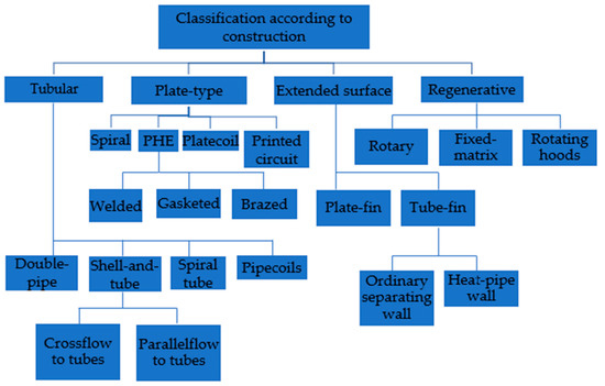
Figure 1 shows the most common classification according to construction.
Figure 1.
Classification of HXs based on construction.
A finned tube HX is made up of a number of tubes with fins attached to the outside which can be normal, transverse, helical, or longitudinal to the tube. Similarly, continuous plate-fin sheets may be attached to the array of tubes by a tight mechanical (press) fit, adhesive bonding, tension winding, soldering, brazing, welding, or extrusion, which can be organized in a staggered or in-line form.
In this type of coil, a fluid for heat transmission, such as oil, water, or refrigerant, flows inside round, rectangular, or elliptical-shaped tubes exchanging heat with another medium, such as air, which flows between the fins. A good overview of the thermal characteristics of plate-finned and unfinned tube heat exchangers can be found in
[3] where the authors address not only the most important thermofluid correlations, but also the influence of the most important design parameters on the performance of HXs. The impact of the fin type and geometry on the performance is instead discussed extensively by Basavarajappa
[4] who concluded that better performance can be obtained with a larger fin area and by creating turbulence in the fluid, which also causes bulk fluid mixing.
Some of the extended surface exchangers are compact: an HX with a surface area density greater than 700 m
2/m
3 is defined as a compact heat exchanger (CHX), when it is above 10.000 m
2/m
3 it can be classified as a micro heat exchanger
[5]. CHXs of plate-fin and tube-fin types are widely used as vehicular HXs, evaporators and condensers in refrigeration, in the air-conditioning industry, automotive radiators, etc. Their strengths can be compactness as well as lightness and reduced production costs simultaneously achieving high heat transfer performance with low pressure drop. Compact heat exchangers’ most recent scientific and technological advances are illustrated in
[6][7][8][6,7,8]. Following a life-cycle approach, Hesselgreaves et al.
[6] shared an interesting exergetic analysis of heat exchangers seen as part of a system. The same method was applied by Zohuri
[7], who performed a thermal study beginning with the design of compact heat exchangers and continuing through the operational and safety steps. In his work, Zohuri also suggested alternative designs with the aim to maximize the exchanger heat transfer rate. The reduction of fouling in heat exchangers and their systems, however, is given special attention by Klemes et al.
[8], who describe fouling deposition and threshold fouling mechanisms and also offer practical knowledge of the most recent process integration techniques.
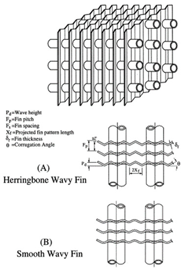
Furthermore, different fin configurations are possible for finned tube heat exchangers, as shown in
Figure 2. It has been shown that the fin type and geometry are some of the parameters that most influence the performance of an exchanger both in terms of heat transfer rate and pressure drops
[9]. The HXs with fins that generate turbulent flow through corrugation, louvers, and vortex generators develop a greater heat transfer rate, but, on the other hand, there is an increase in flow resistance and therefore an increase in pressure drops.
Figure 2.
Different fin types for wavy finned tube heat exchangers [9].
In the last decades, the growing cost of energy and raw materials has forced more and more efficient design of heat exchangers to avoid unnecessary oversizing or malfunctions of these devices. So various mathematical models, and analytical and experimental studies were developed to model the HXs and predict, as efficiently as possible, the performances in terms of heat transfer rate and pressure drops.
2. Heat Exchanger Design Procedure
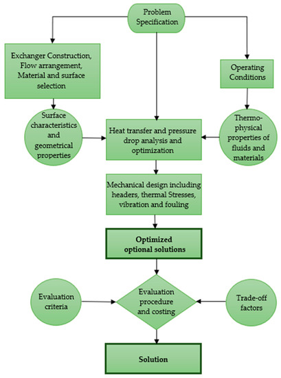
The design process of a heat exchanger is a very complex problem as there are many involved parameters to take into account, with complex correlations. Establishing a correct design procedure is the first step for designing an efficient exchanger and avoiding malfunctions. The design aim is certainly to satisfy the process requirements; therefore the designers must obtain all the information such as fluids flow rates, operating and maximum pressures, temperatures, and also all the constraints of cost, space, and types of materials. A schematic representation of a typical design procedure can be seen in Figure 3. Designers select the construction type of the device, geometry, and all the materials involved, taking into consideration not only the operating conditions but also issues concerning costs, maintenance, reliability, and safety of the device.
Figure 3.
Schematic representation of heat exchanger design methodology.
The HX design process can be classified as a sizing problem (design problem), where the goal is to determine the size of the exchanger, or a rating (performance analysis), where the exchanger already exists or has been chosen and the performance needs to be assessed
[10]. Often, the solutions to this problem are many and then the choice is guided by other criteria such as costs. If the chosen exchanger does not fully satisfy all the requirements, another design must be chosen through an iterative procedure. Once the thermohydraulic performance design has been completed, the second step is to determine the mechanical properties by the design of inlet and outlet nozzles, connectors, temperature and pressure measurement devices, etc. In addition, steady-state and transient thermal stress studies must also be performed. Another very important aspect is maintenance: the positioning and configuration of the exchanger must allow correct cleaning and easy accessibility to all the components, especially those most exposed to problems of corrosion, erosion, and vibrations. Once the mechanical design has also been completed, the cost analysis has to be performed to obtain to the optimal solution of an exchanger that satisfies all the requirements at the minimum cost. The costs of materials, manufacturing, testing, installation, operation, and maintenance have to be included in the analysis.
3. Multi-Sscale Mmodels: The Hthe hybrid Mmethod
Multi-scale models are very flexible and suitable for different HX geometries and working conditions because they integrate analytical methods’ benefits with more accurate numerical approaches. The hybrid method is an alternative design procedure developed by Starace et al. [11] and based on an algorithm that uses a multi-scale method, based on data from either analytical, numerical, or experimental investigations. The hybrid approach was originally used on compact cross-flow HXs, where the entire geometry was split into a number of control volumes. Through the application of a regression technique, Carluccio et al.’s [12] thermo-fluid dynamics simulation findings on the two finned surfaces of the HXs were used to develop the prediction functions of heat transfer, extending the local results over the whole geometry of the HX. By starting with small-scale experimental tests, Fiorentino and Starace [13] developed another application of the hybrid technique for countercurrent evaporative condensers to assess their performance. Results indicate that, when compared to experimental tests, the method is accurate and can determine the air temperature and relative humidity at the output with errors of 2.5% and 4%, respectively. Starace et al. [14] employed this technique on a plate-finned evaporator with a basic refrigerant circuit configuration, using the control volume approach (Figure 4).
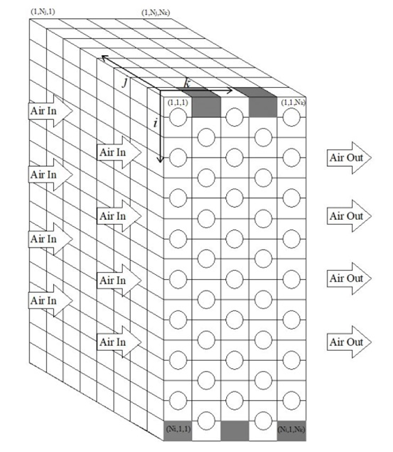
Figure 4.
The scheme of the HX’s geometry through a three-dimensional matrix [14].
Then, Starace et al. [15] achieved progress in the development of the hybrid technique by using it on evaporators with complex circuit layouts to assess the impact of circuitry configuration on overall performance in terms of heat transfer rate and refrigerant pressure drops. Then, additional tests were conducted while taking into account various refrigerants and changing the fluid conditions at the input [16]. Finally, the hybrid approach algorithm underwent additional modifications to make it even more adaptable and compatible with predictions of the performance of real heat exchangers [17]. Other tests were conducted by adjusting the operating conditions, such as the temperature gradient between refrigerant and air at the inlet and the air relative humidity.
References
[1] Bergman, A.A.; Incropera, F.P. Fundamentals of Heat and Mass Transfer; John Wiley & Sons: Hoboken, NJ, USA, 2011.
[2] Rohsenow, W.M.; Hartnett, J.P.; Cho, Y.I. Handbook of Heat Transfer, 3rd ed.; McGraw-Hill: New York, NY, USA, 1998.
[3] Tahseen Ahmad Tahseen; Ishak, M.; Rahman, M.M. An overview on thermal and fluid flow characteristics in a plain plate finned and un-finned tube banks heat exchanger. Renew. Sustain. Energy Rev. 2015, 43, 363–380.
[4] Basavarajappa, S.; Manavendra, G.; Prakash, S.B. A review on performance study of finned tube heat exchanger. J. Phys. Conf. Ser. 2020, 1473, 012030.
[5] Kakac, S.; Liu, H. Heat Exchangers: Selection, Rating and Thermal Design, 2rd ed.; CRC Press: Boca Raton, FL, USA, 2002.
[6] Hesselgreaves, J.E.; Law, R.; Reay, D. Compact Heat Exchangers: Selection, Design and Operation, 2nd ed.; Butterworth-Heinemann, 2016.
[7] Zohuri, B. Compact Heat Exchangers, 1st ed.; Springer: Cham, Switzerland, 2017.
[8] Klemes, J.J.; Arsenyeva, O.; Kapustenko, P.; Tovazhnyanskyy, L. Compact Heat Exchangers for Energy Transfer Intensification: Low Grade Heat and Fouling Mitigation, 1st ed.; CRC Press: Boca Raton, FL, USA, 2015.
[9] Wang, C.-C.; Hwang, Y.-M.; Lin, Y.-T. Empirical correlations for heat transfer and flow friction characteristics of herringbone wavy fin-and-tube heat exchangers. Int. J. Refrig. 2002, 25, 673–680.
[10] Shah, R.K.; Sekulic, D.P. Fundamentals of Heat Exchanger Design; John Wiley & Sons: Hoboken, NJ, USA, 2003.
[11] Starace, G.; Fiorentino, M.; Longo, M.P.; Carluccio, E. A hybrid method for the cross flow compact heat exchangers design. Appl. Therm. Eng. 2017, 111, 1129–1142.
[12] Carluccio, E.; Starace, G.; Ficarella, A.; Laforgia, D.; Numerical analysis of a cross-flow compact heat exchanger for vehicle applications. Appl. Therm. Eng. 2005, 25, 1995–2013.
[13] Fiorentino, M.; Starace, G. The design of countercurrent evaporative condensers with the hybrid method. Appl. Therm. Eng. 2018, 130, 889–898.
[14] Starace, G.; Fiorentino, M.; Meleleo, B.; Risolo, C. The hybrid method applied to the plate-finned tube evaporator geometry. Int. J. Refrig. 2018, 88, 67–77.
[15] Starace, G.; Macchitella, S.; Fiorentino, M.; Colangelo, G. Influence of circuit arrangement on evaporator performance using the hybrid method. In Proceedings of the 6th IIR Conference on Thermophysical Properties and Transfer Processes of Refrigerants, Vicenza, Italy, 1–3 September 2021.
[16] Starace, G.; Macchitella, S.; Colangelo, G. The hybrid method for the plate-finned tube evaporator design process. In Proceedings of the 76° ATI Conference, Rome, Italy, 15–17 September 2021.
[17] Starace, G.; Macchitella, S.; Colangelo, G. Improvements to the hybrid method applied to the design of plate-finned tube evaporators. In Proceedings of the 77° ATI Conference, Bari, Italy, 12–14 September 2022.