Your browser does not fully support modern features. Please upgrade for a smoother experience.
Please note this is a comparison between Version 1 by Adeel Hassan and Version 2 by Rita Xu.
Additive manufacturing is a key component of the fourth industrial revolution (IR4.0) that has received increased attention over the last three decades. Metal additive manufacturing is broadly classified into two types: melting-based additive manufacturing and solid-state additive manufacturing. Friction stir additive manufacturing (FSAM) is a subset of solid-state additive manufacturing that produces big area multi-layered components through plate addition fashion using the friction stir welding (FSW) concept.
- metal additive manufacturing
- friction stir additive manufacturing
- metallic laminates
1. Introduction
Prior to the industrial revolutions, agriculture, and handicrafts were the main drivers of economies. This trend was altered by the industrial revolution, which turned them into manufacturing-based economies. Industrial revolution is historically catalogued into four sessions illustrated in Figure 1. Before 1830, shifting of manual production to the machinery-based production was known as the first industrial revolution. The era of 1840–1940 is called second industry revolution, which involved the advancement of large-scale energy (electricity, petroleum) and material production. In the automobile and aircraft manufacturing industry, the production rate drastically increased to the mass production [1]. The third industrial revolution is named as digital manufacturing and it began in 1945. In this revolution, the technology moved from analog, mechanical, and electronic systems to the highly connected digital technology [2]. The fourth revolution is direct digital manufacturing and it was introduced by the German government in 2011 [3]. As a new phase, it embraces future technologies such as cyber systems, internet of things (IOT), the internet of services (IOS), robotics, big data, cloud manufacturing, and augmented reality, and has a great impact on the economy as well [4][5][4,5]. Currently, we are living in the fourth industrial revolution epoch which is commonly known as IR4.0.
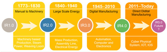
Figure 1. Chronological outline of industrial revolutions.
Additive manufacturing (AM) is the vital part of the IR4.0, which is defined as to convert 3D CAD data to produce physical parts by joining material (metal, ceramic, or polymer) in layer-by-layer fashion [6]. This technology has been at the forefront from the last 30 years, and since from past one decade, it has entered in the mainstream industrialized field [7]. AM process is advantageous over conventional manufacturing such as low material waste [8], excellent part accuracy [9], less human commitment, and ecofriendly [10]. It is adopted in critical engineering fields such as the aerospace and automobile industry, but is still facing challenges to produce physical metallic components [11]. American standard for mechanical testing ASTM-F2792-12a grouped current and future AM technologies into seven families; a complete family tree of AM process is shown in Figure 2 [6]. The classification of AM techniques as per ASTM standard is: (i) binder jetting (BJ), (ii) direct energy deposition (DED), (iii) material extrusion (ME), (iv) material jetting (MJ), (v) powder bed fusion (PBF), (vi) sheet lamination (SL), (vii) and vat photopolymerization (VP). Broadly, material is classified into three classes such as metal, polymer, and ceramic, and AM technologies mainly depend on the class of candidate material [12]. Binder jetting is an AM technique of joining powder particles selectively by using a liquid-based binding agent. Metallic, ceramic, and polymer powder as feed materials are used in this process. Consequently, steel parts with excellent mechanical properties are produced with this process. No support structure is required; however, high level part shrinkage is the key challenge of this method [13]. Direct energy deposition additive manufacturing (DED-AM) is the process of fabrication physical part by depositing metallic powder or feed wire simultaneously in moving substrate under a vacuum or protective atmosphere of inert gas [14], and it is also used for metallic repair work [15]. In comparison to binder jetting, binder jetting yields better grain structure than DED-AM because of lower working temperature [16]. In material extrusion AM, the polymer or thermoplastic composites in wire or powder form as a feed material becomes softened and driven out through the orifice and is stacked to make a physical 3D standard component easily and cheaply as compared to the other AM processes [17][18][17,18]. Another commonly used AM technique in the field of polymer printing is material jetting AM. The droplets of build material are deposited and high-quality thin-walled featured parts with less staircase effect are produced, as compared to the other polymer printing process [19][20][19,20]. In powder bed fusion (PBF) AM, the build material in the form of powder pre-deposited on the bed is selectively diffused by high-source thermal energy to produce dense parts [6]. Since the past 20 years of progress, PBF-AM is still suffering from poor process repeatability [21][22][21,22] and lower deposition rate as compared to the DED-AM-AM [23]. Next, categorization is sheet lamination SL-AM, it is one of the most primitive commercialized AM processes and also known as lamination object manufacturing (LOM). The input material is cut into the desired shape, stacked, and bonded together to form a bulky objects, and the reuse of wrong pasted material is normally discarded [24]. Vat photopolymerization involves hardening of liquid resin that polymerizes when exposed to the light source of specific wavelength [25]. This technique is widely opted by the dental industry [26]. Among these classes, DED-AM, PBF-AM, SL-AM, and BJ-AM have promising potential for production of metallic functional parts of industrial applications [23]. From a variety of feed stock materials of current AM processes, if someone chooses the metallic material, only then AM processes arise into two factions such as melting or beam-based AM, and solid-state or non-beam-based AM.
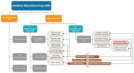
Figure 2. Family tree of current and future additive manufacturing processes-ASTM F2792.
1.1. Melting Based Additive Manufacturing
High energy laser/electron beam or electric arc is used to melt the feed metallic material (wire/powder pre-deposited on bed or feed through nozzle). Powder bed fusion (PBF) and direct energy deposition (DED) are the well-renowned beam-based additive manufacturing processes to produce metallic parts [27]. When high-energy beams interact with feed material, the complicated physical phenomenon of melting of feed material, flow of melting pool, and subsequently solidification occur [28][29][28,29]. Metal vaporization, excessive splashing, and larger heat affected zone (HAZ) involves when high energy beam comes into contact with feed material [30]. In the solidification phase: rapid cooling (103–107 Ks−1), due to the high thermal gradient and complex thermal cycles that might cause partial re-melting of the earlier deposited layer and epitaxial growth. Partial remelting of the already deposited layer plays a role of eradication agent of developed equiaxed grains on the top of the melt pool [31], which promotes textured columnar grain structure. The final mechanical and structural properties of produced parts are intensely affected by the microstructure/grain structure of the part. Most of the researchers reported that parts produced through existing fusion-based additive manufacturing techniques reveals anisotropic behavior and hence, non-uniform microstructure and inferior mechanical properties to the base material [11][30][32][33][34][11,30,32,33,34]. To encapsulate, the methodological framework of the current beam-based AM processes is melting and depositing one thin layer at a time, and it mimics micro-casting or micro-welding. Each melting based AM processes have their own set of advantages, such as good to reasonable surface finish, the ability to print complex geometries [35] with low material wastage, and flexibility in part customization [36]. However, some remarkable challenges, such as inability to process a wide range of non-weldable alloys (Aluminum 2xxx and 7xxx series), extremely high feed material costs, the presence of solidification defects (internal porosity and cavities [37], hot cracking and shrinkage [38], inclusions and high residual stresses [39] etc.) caused by liquid–solid phase transformation, low production volume, high operating costs, and less structural efficiency [33][40][33,40], currently limit the widespread acceptance of melting-based AM. Among these, priority of aerospace and automobile industries is high mechanical and structural efficiency with high production rate. So, these ongoing limitations could be overcome by adopting solid-state AM.
1.2. Solid-State Additive Manufacturing
To avoid the liquid-solid transformation defects, solid-state additive manufacturing is the substitute of existing beam-based AM. Being a solid-state process, there is no melting and no high-energy beam entailed, and input material is joined below its melting temperature. Consequently, solidification defects could be easily eliminated, which further harvests better microstructure along with improved mechanical properties. Ultrasonic additive manufacturing (UAM), cold spray additive manufacturing (CSAM) [41], friction stir additive manufacturing (FSAM), and additive friction stir deposition (AFSD) [42] are sub-classes of solid-state AM process.
2. Friction Stir Additive Manufacturing (FSAM)
Friction stir additive manufacturing is an emerging AM technique and falls in the category of sheet lamination AM (already discussed in the introduction para). Friction stir welding as an additive technique was first introduced by White [43] in 2002 by filing a patent. The proposed technique adopted commercially by Airbus in 2006 to produce wing ribs of Al-Li 2025 [44], and witnessed the excellent inter bonding of layers with more environmentally and greater production rate along with minimum material waste [45]. Unlikely, this could not gain much attention among the industrial and research community due to the lack of terminology and insufficient research, which hindered the further progress. Dilip et al. [46] used friction surfacing and friction welding as potential techniques for AM, and they called this friction stir deposition (FSD). Following that, Boeing in 2012 [47] evaluated the technique and nominated FSAM as a building tool for energy efficient structure developments. Curiously, after Airbus and Boeing’s works, there was no publication on FSAM until the work of Palanivel et al. [32][48][32,48] in 2015. Research works of Palanivel et al. have successfully created newer avenues in FSAM area. The timeline and development of FSAM is demonstrated in Figure 3.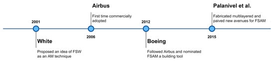
Figure 3. Timeline and development of FSAM.
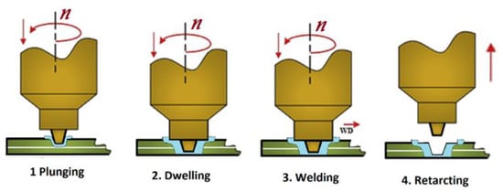
Figure 4. Stages involved in two layer joining (FSLW).
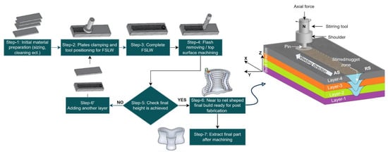
Figure 5. FSAM schematic illustration and final four-layered build obtained.
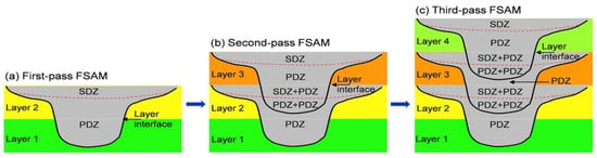
Figure 6. Schematic of stir zones of the FSAM build: (a) first pass FSAM; (b) second pass FSAM; and (c) third pass FSAM.
Table 1. Merits and limitations of FSAM over existing meting-based AM [12][54][55][56][57][58][12,54,55,56,57,58].
| Merits | Limitations |
|---|---|
| Homogeneous, equiaxed ultrafine microstructure. | Incompetence to fabricate intricate shapes/complex geometry. |
| High structural integrity with superior mechanical properties. | Tool wear and workpiece clamping dilemmas. |
| Solidification defects are negligible. | Considerable residual stresses. |
| High production rate and volume as no vacuum/inert gas chamber required. | Prior layer flash removing necessary before adding next layer. |
| Less energy consumption (~2.5% of fusion-based process). | Some post processing needed to obtain net shape. |
| There is no powder related restriction as feed material is in plate form. | |
| Smaller heat affected zone (HAZ). | |
| More sustainable due to fumeless process or very less of greenhouse gases. | |
| Non-welded high-strength alloys and dissimilar alloys in graded fashion can be processed. |