Your browser does not fully support modern features. Please upgrade for a smoother experience.
Please note this is a comparison between Version 1 by Ying Chen and Version 2 by Conner Chen.
The electron transport layer (ETL) acts as a function of collecting electrons and blocking the transport of holes to the FTO electrode in the PSC. The mesoporous structure of the ETL promotes the crystallization and film formation of perovskite and shortens the migration path of photogenerated electrons. A suitable ETL should have an energy band position that matches the perovskite material.
- perovskite solar cells
- electron transport layer
- perovskite preparation
1. Introduction
The serious consumption of energy and environmental problems have aroused people’s attention to renewable energy. Over the past decade, solar energy systems have proved to be the most compelling of all renewable energy systems [1]. Perovskite is considered a hopeful photovoltaic candidate due to its high optical absorption coefficient, tunable band gaps, long charge carrier life, low cost, and simple preparation process [2][3][4][5][6][7][2,3,4,5,6,7]. The power conversion efficiency (PCE) of perovskite solar cells (PSCs) has jumped from 3.8% to 25.73% (certified) [8]. As shown in Figure 1, ABX3 is the general formula crystal structure of perovskite materials. A is a large radius cation such as CH3NH3+ (MA+), NH2CH=NH2+ (FA+), Cs+, Ca2+, and Sr2+ B is Pb2+, Sn2+, Ti4+, Nb5+, Mn4+, and other small radius cations. X are anions such as O2, F−, Cl−, Br−, and I− [9][10][9,10]. The tolerance factor t could be used to calculate the perovskite crystal structure stability. The t = (RA + RX)/2–√2(RB + RX), where RA, RB, and RX refer to the ionic radii of A, B, and X site ions, separately. In general, the tolerance factor of structurally stable, highly symmetrical cubic structured perovskites usually ranges from 0.813 to 1.107 [11][12][11,12]. Within this range of tolerance factors, different stabilities and band structures of perovskite materials were obtained by doping or replacing the A, B, and X site ions [13]. For example, adding Sn to Pb-based perovskites could reduce the band gap and effectively broaden the absorption spectrum in the near-infrared [14][15][14,15]. With this advantage, perovskite materials can be combined with different forbidden bandwidths of light-absorbing materials, such as Si and quantum dots, to make stacked cells, such as perovskite-Si [16][17][16,17], perovskite-chalcogenides [18][19][18,19], and perovskite-quantum dots [20].

Figure 1.
Typical crystalline structure of perovskite.
Perovskite solar cells are primarily divided into mesoporous structures and planar structures. The planar structures contain regular planar structures (n-i-p) and inverted planar structures (p-i-n) [21]. The typical mesoporous structures from bottom to top are a transparent conductive glass substrate (FTO, ITO), an electron transport layer (ETL), a mesoporous layer (mainly TiO2, Al2O3, etc.), a perovskite layer, a hole transport layer (HTL), and metal electrodes (Figure 2a). The ETL plays the role of electron transport and hole blocking. The mesoporous layer is relatively thin. Thus, a perovskite layer could cover it completely to isolate the mesoporous material from HTL [22]. The HTL plays the role of hole transport. This structure avoids interfacial compounding of charges while maximizing charge transfer efficiency, enhancing the open-circuit voltage and charge collection efficiency, and most of the higher-certified efficiency perovskite solar cells use this structure [23]. However, the preparation of the mesoporous layers requires high-temperature processing, which limits its application in flexible devices.
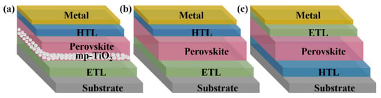
Figure 2. Three representative structures of PSCs: (a) mesoporous structures; (b) regular planar (n-i-p) structures, and (c) inverted planar (p-i-n) structures.
The planar structure is similar to a “sandwich structure”. The perovskite layer is placed between the n-type material and the p-type material, which benefits from the excellent bipolar carrier transport properties of perovskite materials. They have n-i-p and p-i-n types (Figure 2b,c). The n-i-p structure is simplified from the mesoporous structure. The p-i-n structure is developed mainly from the structure and materials of classical organic solar cells. Planar-structured perovskite solar cells do not have a mesoporous layer, which is suitable for the fabrication of large-area flexible devices at low temperatures. Their preparation process is relatively simple too. However, without mesoporous material as a backbone, the perovskite morphology is difficult to control, the repeatability of the devices is poor, and additional auxiliary means are required to improve the film quality.
2. Electron Transport Layer (ETL)
The ETL acts as a function of collecting electrons and blocking the transport of holes to the FTO electrode in the PSC. The mesoporous structure of the ETL promotes the crystallization and film formation of perovskite and shortens the migration path of photogenerated electrons. A suitable ETL should have an energy band position that matches the perovskite material. The conduction band position should be slightly below the conduction band minimum of the perovskite layer to facilitate electron injection, while the valence band is at a deeper position to effectively block holes and has a high electron conductivity to ensure electron transport and collection [24]. TiO2, an N-type oxide, is considered the most common choice for ETL material, with a wide band gap (~3 eV), easy-to-tune electronic properties, ability to form both dense and mesoporous layers, and producible easily and at low cost. TiO2 has two thermodynamically stable crystal phases: anatase and rutile. Kim et al. [25] found that the anatase phase showed better performance than the rutile phase. However, Wang et al. [26] showed that a rutile TiO2 ETL had better conductivity and match with the MAPbI3 layer, which significantly enhanced performance. Several new methods to prepare TiO2 for flexible devices or mass production have emerged in recent years, such as ball milling [27], ultrasonic spray [28][29][28,29], atomic layer deposition [30], inkjet-print [31][32][33][31,32,33], hydrothermal [34][35][36][34,35,36], sol–gel chemistry [37], low-temperature CO2 plasma [38], and low-temperature microwave [39][40][39,40]. The morphology of TiO2 has also attracted much attention. TiCl4 was a good choice. Jarwal et al. [41] obtained TiO2 nanorod arrays by solvothermal etching and/or TiCl4 treatment to improve their surface-to-volume ratio and direct carrier transportation. Shahvaranfard et al. [42] adopted TiCl4 treatment and a PC61BM monolayer to obtain a TiO2 nanorod array ETL. Lu et al. [43] exquisitely tuned TiCl4 precursor solution to construct nanowire arrays and nanoflower composite of TiO2 film. The composite structure has the characteristics of a short direct charge transmission path, small leakage current and charge transmission resistance, slow recombination rate, and large light harvest. The best PCE was more than 20%. Doping is a great method for improving the quality of TiO2. The commonly doped materials include Li [44], Mg [45], Zn [46][47][46,47], EuAc3 [48], Nb [49], Ce [50][51][50,51], Zr [52][53][52,53], Ta [54][55][54,55], and graphene quantum dots (QDs) [56]. The performance of related PSCs is shown in Table 1. Bilayer ETLs also work well, such as TiO2/SnO2 [57][58][59][60][61][62][63][64][65][66][57,58,59,60,61,62,63,64,65,66], TiO2/ZnO [67][68][67,68], TiO2/WO3 [69][70][69,70], TiO2/graphene [71][72][71,72], TiO2/fullerene [73], and TiO2/NiO [74]. SnO2, as an ETL material, has excellent electrical and optical properties. Its disadvantage is that there are surface defects and hysteresis phenomena. Cao et al. [75] used pyrrolidine fullerene C60-substituted phenol (NPC60-OH) to weaken the hysteresis of SnO2. The SnO2/NPC60-OH-based PSCs obtained a PCE of 21.39%. Liang et al. [76] passivated SnO2 with chlorine to improve electron mobility. The open-circuit voltage increased from 1.195 V to 1.135 V. Jiang et al. [77] adopted phosphoric acid to increase the electron collection efficiency of SnO2 by excluding its surface dangling bonds. Wang et al. [78] passivated SnO2 ETLs by fullerene to improve the PCE and reproducibility. Cao et al. [79] modified the SnO2 ETL by sulfur-doped graphite carbon nitride nanosheets to obtain a PCE of 20.33%. Liu et al. [80] introduced nontoxic phytic acid (PA) into the SnO2 to obtain the ETL with fewer defects. PA-SnO2-based PSCs had a high PCE of 21.43%. Lin et al. [81] obtained PCE of 21.87% with a SnO2 ETL by precursor engineering. Li et al. [82] utilized vacuum-assisted annealing to synthesize a SnO2 ETL at 100 °C for flexible solar cells, with a PCE of 20.14%. Liu et al. [83] adopted polydentate phytic acid dipotassium (PAD) to passivate the defects of the SnO2/perovskite interface and obtained a PCE of 19.52%. Xu et al. introduced functional polymers such as polyethylene oxide-polypropylene oxide-polyethylene oxide (P123) [84] and poly(amidoamine) (PM) [85] in SnO2 precursor to construct a uniform and dense SnO2 ETL. The PM-treated PSC had a PCE of up to 22.93%, with negligible hysteresis. Zong et al. used continuous spin coating to fabricate SnO2@K:Cs [86] and SnO2@Na:Cs ETLs [87], respectively. The better PCE was 22.06%, based on a SnO2@Na:Cs ETL. Gu et al. [88] added NaCl to raise the charge exchange between the SnO2 ETL and perovskite and obtained a PCE of 21.2%. Large-scale fabrication methods include vacuum thermal evaporation [89], magnetron sputtering [90], radio frequency [91][92][91,92], sputtering deposition [93], spray deposition [94][95][94,95], atomic layer deposition [96], hydrothermal [97], and printing [98]. Doping can improve the properties of SnO2. Common doping materials include Ga [99][100][99,100], Ta [101], Nb [102][103][102,103], Zn [104], Li [105], Zr/F [106], KF [107], Cl [108], NH4Cl [109], and graphene quantum dots [110]. The performance of related PSCs is shown in Table 1. Double ELT is also a valid way to promote the performance of SnO2, such as SnO2/CdS [111], SnO2-Ti3C2 Mxene [112], SnO2/ZnO [113][114][115][113,114,115], SnO2/TiO2 [116][117][116,117], SnO2/carbon nanotubes [118], SnO2/KCl [119], SnO2-assisted CdS [120], and NH2-ZnO@SnO2 [121]. ZnO, as another ETL material, has relatively large electron mobility, good light transmittance, proper work function, stability, low cost, and low-temperature preparation. Environmental friendliness, low-temperature, and large area are still hot topics of preparation method research. Zhang et al. [122] promoted the energy-level alignment and charge carrier extraction of ZnO by the sol–gel method. They also deposited ZnO by a simple water-based processing route [123]. Zhao et al. [124] used magnetron sputtering to prepare big-size grains, low defect state density, and a great optical ZnO ETL. They found that the PSCs based on an Ar/O2 ratio of 1:4 treated ZnO had a maximum PCE of 17.22%. However, ZnO shows less chemical compatibility with the perovskite layer. Surface passivation and ion doping are frequently used strategies. Yang et al. [125] optimized the hydrophilicity of the ZnO surface with three amino compounds. They found that the PSCs with isobutylamine (IBA) modification exhibited improved stability, and PCE can reach 18.84%. Eswaramoorthy et al. [126] used plasmonic nanoparticles to modify ZnO for high PCE and stability. Commonly used doping materials are Al [127], Co [128], Mg [129][130][129,130], reduced graphene oxide (rGO) sheet/Ag [131], and PbS [132]. The performance of related PSCs is shown in Table 1.Table 1.
Summary of various PSCs performances using doped ETL.
| ETL | Device Configuration | Jsc (mA cm−2) |
VOC (V) | FF | PCE (%) | Ref. | |
|---|---|---|---|---|---|---|---|
| TiO2 | Li | FTO/c-TiO2/Li-m-TiO2/MAPbI3/Spiro-OMeTAD/Au | 22.86 | 1.101 | 0.699 | 17.59 | [44] |
| Mg | FTO/Mg-TiO2/Perovskite/Spiro-OMeTAD/Au | 22.27 | 1.08 | 0.609 | 14.65 | [45] | |
| Zn | FTO/Zn-TiO2/MAPbI3/Spiro-OMeTAD/Au | 21.83 | 1.10 | 0.734 | 17.60 | [46] | |
| Zn | FTO/Zn-TiO2 NAs/(FAPbI3)0.87(MAPbBr3)0.13/CuSCN/Carbon | 22.25 | 0.956 | 0.679 | 14.45 | [47] | |
| EuAc3 | FTO/EuAc3-c-TiO2/CsPbI3/P3HT/Au | 21.20 | 1.1 | 0.77 | 17.92 | [48] | |
| Nb | FTO/Nb-TiO2/FA0.79MA0.16Cs0.05Pb(BrXI1−X)3/Spiro-OMeTAD/Au | 24.70 | 1.12 | 0.78 | 21.30 | [49] | |
| Ce | FTO/Ce-TiO2/MAPbI3/Spiro-OMeTAD/Ag | 21.95 | 1.07 | 0.69 | 16.18 | [51] | |
| Zr | FTO/Zr-TiO2/MAPbI3/Spiro-OMeTAD/Ag | 23.66 | 0.92 | 0.567 | 12.35 | [52] | |
| Zr | FTO/Zr-TiO2/MAPbI3/Spiro-OMeTAD/Au | 23.57 | 1.076 | 0.716 | 18.16 | [53] | |
| Ta | FTO/Ta-TiO2/Cs0.1(FA0.83MA0.17)0.9Pb(I0.83Br0.17)3/Spiro-OMeTAD/Ag | 22.45 | 1.13 | 0.77 | 19.62 | [54] | |
| GQDs | FTO/c-TiO2/GQDs-mTiO2/Cs0.05(FA0.83MA0.17)0.95 Pb(I0.83Br0.17)3/Spiro-OMeTAD/Au | 21.92 | 0.97 | 0.63 | 14.36 | [56] | |
| SnO2 | Ga | ITO/Ga-SnO2/(FAPbI3)x(MAPbBr3)1-x/Spiro-OMeTAD/Ag | 23.90 | 1.068 | 0.714 | 18.18 | [99] |
| Ga | FTO/Ga-SnOx/CsPbBr3/Carbon | 7.58 | 1.311 | 0.602 | 5.98 | [100] | |
| Ta | ITO/Ta-SnO2/Perovskite/Spiro-OMeTAD/Au | 22.79 | 1.161 | 0.786 | 20.8 | [101] | |
| Nb | FTO/Nb-SnO2/CsPbBr3/Carbon | 8.92 | 1.31 | 0.731 | 8.54 | [103] | |
| Zn | FTO/Zn-SnO2/CsPbBr3/CuPc/Carbon | 23.40 | 1.098 | 0.692 | 17.78 | [104] | |
| Li | Li-FTO/SnO2/Al2O3/MAPbI3/Carbon | 22.18 | 0.76 | 0.59 | 10.01 | [105] | |
| Zr/F | FTO/Zr/F-SnO2/Perovskite/Spiro-OMeTAD/Au | 24.39 | 1.105 | 0.712 | 19.19 | [106] | |
| KF | ITO/KF-SnO2/CsPbI2Br/Spiro-OMeTAD/MoO3/Au | 14.79 | 1.31 | 0.792 | 15.39 | [107] | |
| Cl | FTO/Cl-SnO2/Perovskite/Spiro-OMeTAD/Au | 24.25 | 1.07 | 0.73 | 18.94 | [108] | |
| NH4Cl | ITO/NH4Cl-L-SnO2/NH4Cl-H-SnO2/Perovskite/PEAI/Spiro-OMeTAD/Au | 23.60 | 1.208 | 0.762 | 21.75 | [109] | |
| GQDs | ITO/GQDs-SnO2/MAFAPbI3Cl3-x/Spiro-OMeTAD/Ag | 24.40 | 1.11 | 0.78 | 21.10 | [110] | |
| ZnO | Co | PET/ITO/Co-ZnO/MAPbI3/Spiro-OMeTAD/Au | 14.30 | 1.04 | 0.47 | 7.00 | [128] |
| Mg | FTO/Mg-ZnO/MAPbI3/Spiro-OMeTAD/Ag | 25.06 | 0.83 | 0.65 | 13.52 | [130] | |
| rGO/Ag | FTO/rGO/Ag-ZnO/MAPbI3/Spiro-OMeTAD/Au | 17.82 | 0.90 | 0.72 | 11.03 | [131] | |
| PbS | ITO/PbS-ZnO/MAPbI3/Spiro-OMeTAD/Ag | 22.8 | 1.14 | 0.79 | 20.53 | [132] | |