Your browser does not fully support modern features. Please upgrade for a smoother experience.
Please note this is a comparison between Version 1 by Songlin Ding and Version 4 by Rita Xu.
Titanium alloys are extensively used in various industries due to their excellent corrosion resistance and outstanding mechanical properties. The machining of additively manufactured titanium alloys presents additional machining challenges as the alloys exhibit unique properties compared to their wrought counterparts, including increased anisotropy, strength, and hardness. The associated higher cutting forces, higher temperatures, accelerated tool wear, and decreased machinability lead to an expensive and unsustainable machining process.
- additive manufacturing
- machining
- cutting force
1. Introduction
Titanium and its alloys are applied in a wide range of industries due to their outstanding mechanical and chemical properties, such as high strength/weight ratio, high elastic modulus, and excellent corrosion resistance. Specifically, the remarkable biocompatibility and good mechanical properties at elevated service temperatures make titanium alloys especially desirable for use in biomedical and aerospace industries, respectively [1][2][1,2]. However, the machining of titanium alloys is challenging due to the high strength, low thermal conductivity, and high chemical reactivity of the material [3][4][5][3,4,5]. Due to these properties, it is common to machine titanium alloys with a low cutting speed of less than 90 m/min, which significantly reduces productivity and increases machining costs, when compared to other alloys, such as aluminium, that can be machined with cutting speeds as high as 2500 m/min. The comparatively high feedstock cost of titanium also imposes further economic challenges when machining parts for cost-sensitive applications with high buy-to-fly ratios, which result in large amounts of waste [6][7][6,7].
Additive manufacturing (AM) is a new class of manufacturing processes which can produce complex parts directly from a 3D digital model using a layer-by-layer approach with little material waste. Compared to conventional machining processes, such as milling, turning, and grinding in which parts are produced by subtracting redundant materials from feedstock, additively manufactured parts are produced by sequentially consolidating layers of material [8][9][10][8,9,10]. The layered manufacturing approach effectively decomposes a complex and difficult-to-shape 3D part geometry into a series of comparatively simple to manufacture 2D layers. In comparison to conventional machining processes, AM imposes few design constraints on part geometry and requires a low setup effort without the requirement for custom tooling. This allows for the manufacture of complex parts that are highly customisable. AM processes were first commercialised in 1986 through the stereolithography (SLA) process and were only suitable for the manufacture of plastic prototype components [11]. The commercialisation of AM technology for the manufacture of metal components began in the 1990s and has seen extensive development since then [12]. Through continuous development over the past 30 years, it is now possible to build fully dense, functional metallic components with complex geometries for use in demanding industrial applications [13]. For example, as of August 2021, GE Aviation has produced 100,000 additively manufactured fuel nozzle tips for its LEAP jet engines used in Boeing 737 and Airbus 320 [14]. By replacing 855 conventional parts with 12 consolidated components manufactured by AM, GE Aviation has significantly reduced manufacturing process complexity, while also increasing performance, which contributed to a 20% increase in engine fuel efficiency [15].
Despite the advantages of additive manufacturing, metal parts produced by AM processes can exhibit inferior properties compared to wrought machined parts, including higher surface roughness, porosity, dimensional variability, and residual stresses [16][17][16,17]. In particular, the high-surface roughness can significantly reduce fatigue life for components subjected to dynamic loading, thereby limiting suitable application areas. As such, additively manufactured metal parts may need to be subjected to various post-processing processes, including machining, in order to obtain acceptable surface quality [18][19][18,19], although chemical and electrochemical methods can be applied to improve surface finish of parts with unique geometrical structures, for example, the scaffolds for bone tissue engineering and cellular foams [20][21][22][20,21,22]. A significant number of studies have been carried out on the machining of wrought Ti alloys in the past decades. These studies have focused either on the development of specially designed cutting tools and new tool materials [23][24][23,24], optimisation of cutting parameters, application of new cooling media and tribology theories [25], or on the investigation of hybrid machining processes such as thermal-assisted machining (TAM) [26][27][28][29][30][26,27,28,29,30]. Since Ti-6Al-4V is the most widely used titanium alloy constituting 50% of total titanium alloy production worldwide, the machining of Ti-6Al-4V has become one of the most widely studied subjects [31][32][33][31,32,33].
The microstructure and mechanical properties of additively manufactured titanium alloys are notably different from their wrought counterparts due to recurring rapid heating and cooling thermal cycles that occur during common metal AM processes [34]. The processing conditions can also vary between specific AM process, resulting in different part mechanical performance, microstructure characteristics, and surface integrity even for the same feedstock material composition [35]. For example, it has been found that Ti-6Al-4V manufactured by Laser Powder Bed Fusion (PBF-LB), the most widely used AM technology, exhibits higher tensile and yield strength than traditionally wrought Ti-6Al-4V due to the presence of higher residual stress and refined α′ martensite resulting from rapid PBF-LB heating and cooling cycles [36]. Similarly, PBF-LB-processed Ti-6Al-4V alloy has been reported to also exhibit higher Young’s modulus [37]. Another factor that drastically affects the mechanical strength of Ti alloys is the oxygen content. Controlling the addition of oxygen, which induces the solution-strengthening phenomenon in the manufacturing process, can improve the mechanical properties of additively manufactured parts [38][39][40][38,39,40]. In additional to differences in machinal properties, the surface roughness, Ra, of PBF-LB manufactured parts (typically 5–40 µm [41]) also differs compared to their machined counterparts (typically 0.4–6.3 µm [42]). The unique properties of PBF-LB parts subsequently affect tool wear, cutting force, cutting temperature, and formation of chips, resulting in significant differences between the machining of additively manufactured and wrought titanium alloys [43][44][43,44].
2. Additive Manufacturing Processes
The AM process workflow starts with a digital 3D model of the part file, formulated as surface mesh (commonly a stereolithography (STL) file), which is digitally subdivided into individually processable layers for which material deposition or fusion tool paths are generated. During the build process, the tool paths are consolidated in a layer-by-layer approach to produce parts without the need for any custom tooling. The layer-by-layer manufacturing approach effectively deconstructs complex and difficult-to-shape 3D geometry into a series of relatively simpler to shape 2D layers. This key characteristic allows AM to produce parts with unprecedented levels of geometric complexity and design freedom [45][46][47][54,55,56]. A range of AM processes have been developed, which vary in their material feedstock form and material consolidation approach. The most common metal AM approaches are based on Powder Bed Fusion (PBF) and Direct Energy Deposition (DED) techniques [48][49][50][57,58,59]. In a PBF process, a thermal point source scans and selectively melts and fuses the top layer of a bed of atomised metal powder feedstock according to the pre-programmed toolpaths and layers which constitute the desired part. The melt pool rapidly solidifies, the build substrate is lowered by one layer thickness, new powder is deposited, and the next layer is selectively melted. The process repeats until the part build is completed. Following build completion, the unfused powder surrounding the solidified part is removed for reuse in subsequent builds. The ability to rapidly reuse unfused powder in PBF processes provides a significant advantage in material use efficiency compared to conventional subtractive machining processes, which may generate substantial amounts of waste swarf. In the case of PBF-LB (Figure 1), the irradiating heat source is a high powered, mirror-actuated laser (typically 100–2000 W and ~1 μm wavelength) that is sufficient to melt and fuse the metal powder layers (typically 30–90 μm thick) [51][52][60,61]. The representative lasers applied in the PBF-LB process include CO2 laser, Nd: YAG laser (neodymium-doped yttrium aluminum garnet laser), and Yb-fiber laser (ytterbium-doped fiber laser) [51][52][53][60,61,62]. The build chamber is filled with an inert gas (such as argon), and the build substrate onto which the part is built is preheated (preheating temperature can be up to 1200 C [54][55][63,64]) to reduce the thermal gradients between the solidifying layers and the substrate. However, the thermal gradients remain high and PBF-LB parts are prone to high levels of residual stress which, in extreme cases, can cause severe part distortion or fracture. Post-build heat treatments are often applied to relieve stresses [56][65]. The PBF-LB process is also commonly referred to by synonymous trademark terms, such as Selective Laser Melting (SLM) and Direct Metal Laser Sintering (DMLS), that have been popularised by machine manufacturers. However, the terminology standardised by the ASTM International is laser powder bed fusion [57][66]. The Electron Beam-Powder Bed Fusion (PBF-EB) variant of the PBF process (also referred to as Electron Beam Melting (EBM), Figure 1b) uses an electromagnetically actuated electron beam (typically 3–6 kW) to melt the powder layers (typically 50–150 μm) [58][59][67,68]. Compared to PBF-LB, the electron beam allows for higher scanning speeds, powder preheat temperatures, and scan speeds. The higher process temperatures also result in lower thermal gradients and thereby lower residual stress in PBF-EB manufactured parts. However, unlike the PBF-LB, the PBF-EB process needs to take place in a vacuum to avoid E-beam interaction with gas molecules, and this requirement can increase machine cost and setup times [60][69]. Furthermore, the resolution of manufactured parts is lower than with PBF-LB [61][70]. Both PBF-LB and PBF-EB technologies allow the creation of parts with small features, high precision, and complex shapes using a variety of alloys. However, these processes involve a range of complex physical phenomena that can impact part manufacturability, quality, and cost, including powder rheology, laser/E-beam absorption in the powder bed, heat transfer, melting and solidification, melt pool dynamics, microstructure development, and thermomechanical stress. The number of influential parameters associated with these phenomena can be large, with estimates suggesting 130 parameters of relevance to PBF-LB [62][71]. A comprehensive understanding of such influential parameters is the subject of extensive ongoing research [63][72].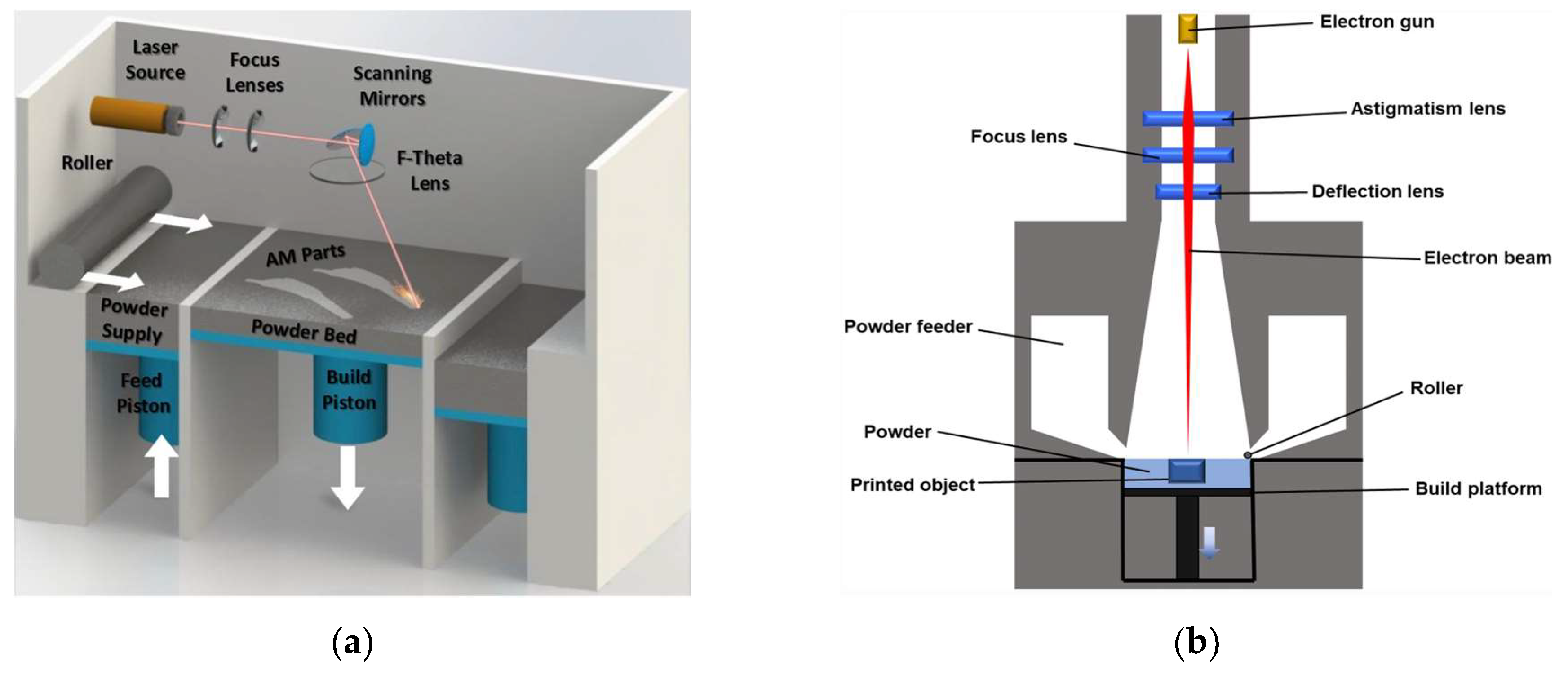

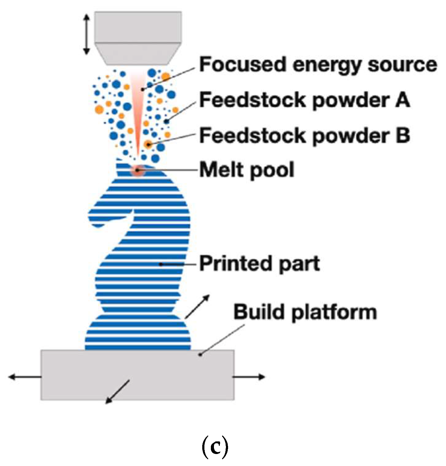
Figure 1.
(
a
) Laser Powder Bed Fusion (PBF-LB) process. (
b
) Electron Beam-Powder Bed Fusion (PBF-EB) process. (
c
) Direct Energy Deposition (DED) process.
3. Machinability of Additively Manufactured Ti-6Al-4V
Additively manufactured metal parts typically have a complex, spatially varying thermal history due to the rapid melting and solidification inherent to metal AM processes. This leads to significant differences in residual stresses, surface roughness (Figure 2) and microstructural characteristics (such as grain size and morphology), which results in different mechanical properties compared to conventionally manufactured parts [35][71][72][35,84,85]. Surface roughness is a decisive factor that impacts the mechanical properties of the final products. A high surface roughness can induce stress concentration on the surface and adversely affect the fatigue properties [73][86]. In general, the surface roughness of additively manufactured Ti alloys is in the range of 10 to 70 μm (Ra), which is significantly larger than that achieved by machining [39][74][75][76][39,87,88,89]. These differences can also influence the machinability of additively manufactured parts by affecting the cutting force, surface integrity, and tool wear. In order to improve the machinability of Ti-6Al-4V, a comprehensive understating of these influential factors is critically important.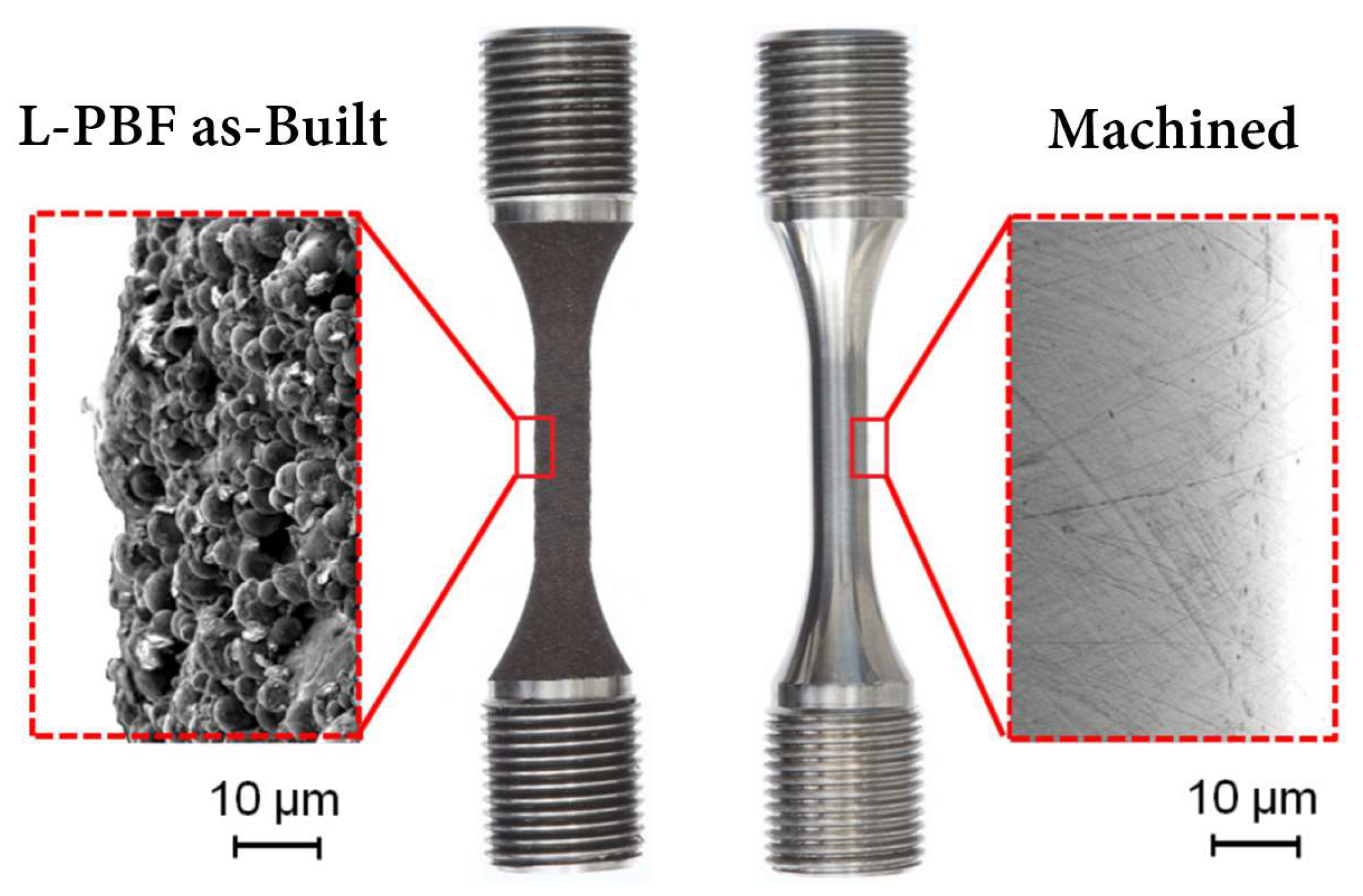
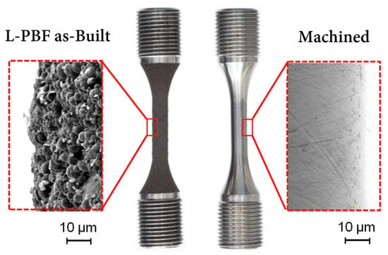
Figure 2. Example PBF-LB surface finish before and after machining process for a Ti-6Al-4V part.
3.1. Cutting Forces in Machining Additively Manufactured Ti-6Al-4V
In order to achieve high machining precision, a cutting tool has to follow specially designed tool paths to minimize dynamic changes in cutting load on the tool [77][78][91,92]. A sudden change of cutting force can cause poor surface integrity of the workpiece, severe tool wear, and premature tool failure. The cutting force generated by the cutting edge is a significant factor in characterising the machinability of titanium alloys [79][93]. During the cutting process, the force is exerted on the contact interface between the cutting tool and the chip [80][94]. Since additively manufactured Ti alloys have a unique acicular microstructure, their strength and hardness can be higher than those of wrought Ti alloys. The higher yield strength can result in a higher cutting force and a high cutting temperature in the cutting zone, which, in turn, will accelerate tool wear rate. The higher hardness can lead to less plastic flow and induce a lower surface roughness [81][95]. The interaction between the cutting tool and workpiece material, as well as the plastic deformation process during the formation of chips, is affected by the enhanced mechanical properties, the changes of which are finally reflected on the cutting force and surface quality. Various experimental studies have been conducted to explore cutting force in machining additively manufactured Ti alloys. Polishetty et al. [82][96] investigated the effect of machining parameters on cutting force and surface roughness of SLM Ti-6Al-4V during the turning process. It was found that higher cutting forces were generated when machining the SLM Ti-6Al-4V alloy due to higher hardness and yield strength. The surface roughness of SLM Ti-6Al-4V was lower because of the high hardness and brittle properties of the material. Shunmugavel et al. [83][97] found that higher cutting forces when turning SLM Ti-6Al-4V led to higher cutting temperature and tool/chip wear, resulting in significant adhesive/abrasive wear. By comparing the machinability of SLM and wrought Ti-6Al-4V, they found that the cutting force was closely related to the mechanical strength and hardness of the material [18], and the change in these factors was the reason that large cutting forces were recorded when machining SLM Ti [82][96]. At a cutting speed of 60 m/min, the cutting force was not affected by the tool wear; at 120 m/min, the cutting force increased a little bit when machining both types of parts. However, it rapidly increased when machining SLM Ti alloy at 180 m/min due to the large concentration of wear on the flank face of the insert. Ming et al. [84][98] compared the mechanical properties of SLM titanium alloy using different machining processes under dry and minimum quantity lubrication (MQL) conditions. It was found that chip curling was more obvious when milling forged Ti-6Al-4V due to its better plasticity, which indicated that the forged Ti-6Al-4V resulted in a larger main cutting force compared to SLM Ti-6Al-4V. The main cutting force when machining SLM components decreased when the cutting speed was at 80 mm/min due to the thermal-softening effect. However, when machining the forged Ti-6Al-4V, the main cutting force increased slowly. For additively manufactured products, the grain size/morphology is also an indicator of their performance. Coarse columnar grains may be generated in the AM process due to the ultra-high temperature gradient, which results in the anisotropic and poor mechanical properties of additively manufactured products [85][86][99,100]. An optimisation of the manufacturing process and alloy composition control has to be conducted to obtain finer equiaxed grains to achieve stronger mechanical properties in the additively manufactured components [87][101]. Kallel et al. [88][102] studied the machinability of Ti-6Al-4V produced by Laser Metal Deposition (LMD). Compared to the wrought Ti-6Al-4V parts, the cutting force when machining LMD-manufactured Ti-6Al-4V was 10–40% higher due to their finer grains, which provided higher yield stress and resistance to plastic deformation. The difference in ductility and microstructure (equiaxed grains and lamellar ones) of the wrought parts and the AM parts [35] led to the surface roughness of the LMD parts being 18–65% rougher than that of the conventional samples. The compressive residual stress of the LMD parts was 11–30% higher than that of the wrought samples.3.2. Surface Integrity
Surface integrity of machined parts is influenced by factors such as machining parameters, cooling conditions, microstructure of the materials, tool wear, and so on. Compared with wrought parts, the surface quality of as-built additively manufactured parts is poor. Lizzul et al. [89][103] investigated the influence of microstructure on the surface integrity of additively manufactured Ti-6Al-4V fabricated by PBF-LB. According to the analysis of AM-induced microstructure, the material structure, including the α phase layer and the β grains, have a significant effect on the surface roughness of the samples. The AM parameters can impact microstructural anisotropy, which further affects the surface integrity of the as-built parts. The scanning strategy affects the size of prior β grain correlated to the microhardness of the workpiece [90][104]. Prior β grain boundaries can impact the crack propagation in AM Ti alloy, which has a significant influence on the tensile and fatigue properties of AM Ti parts [91][105]. The different sizes of β grains of the material are induced by the different thermal histories that have occurred on the fused powder layers. The wider β grains are generated by a lower cooling rate, which leads to thicker α lamellae and lower microhardness. The fracture phenomena occur in correspondence to the α-phase layers that are formed along the β grain boundaries upon heat treatment [38][91][38,105]. The α-phase layers formed along the β grain boundaries represent the AM-produced titanium material discontinuity that weakens the material integrity, which benefits material removal during the cutting process (Figure 3). The samples with a minor β grain width exhibit the highest density of discontinuity in the α-phase layers and show a lower cutting force, resulting in a lower surface roughness. The application of the cryogenic cooling strategy can reduce the surface roughness of the final additively manufactured components.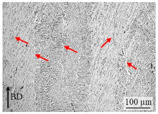
Figure 3. Microstructure along the build-up direction of the PBF-LB Ti-6Al-4V. The red arrows show the α-phase layers along the prior β grains boundaries.
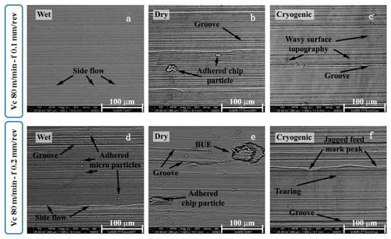
Figure 4. Main surface defects after 8 min of turning when adopting the wet, dry, and cryogenic cooling strategies: (a,d) material side flow, double feed marks, long grooves, and micro-particles adhered on the machined surface; (b,e) wider adhered chip fragments and BUE are attached to the machined surfaces; (c,f) the wavy surface topography along the cutting speed direction and the jagged feed mark peak.
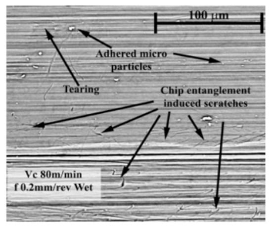
Figure 5. Scratches and adhered particles provoked by chip entanglements after 8 min of wet cutting.
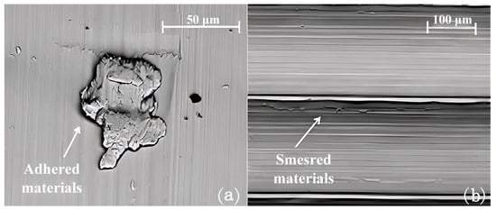
Figure 6. The surface defect generated during dry cutting: (a) adhered material and (b) smeared material.
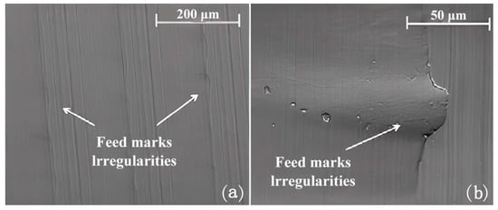
Figure 7. The feed marks and irregularities formed during turning when adopting different cryogenic cooling strategies: (a) 500× and (b) 2000×.