Electrostatic assembly is one of the bottom–up approaches used for multiscale composite fabrication. Since its discovery, this method has been actively used in molecular bioscience as well as materials design and fabrication for various applications. Despite the recent advances and controlled assembly reported using electrostatic interaction, the method still possesses vast potentials for various materials design and fabrication. This review article is a timely revisit of the electrostatic assembly method with a brief introduction of the method followed by surveys of recent advances and applications of the composites fabricated. Emphasis is also given to the significant potential of this method for advanced materials and composite fabrication in line with sustainable development goals. Prospective outlook and future developments for micro-/nanocomposite materials fabrication for emerging applications such as energy-related fields and additive manufacturing are also mentioned.
- electrostatic assembly
- polyelectrolytes
- composites
- ceramics
- polymers
- additive manufacturing
1. Introduction
Nanomaterials exhibit unique properties that are not seen in bulk materials, and this has led to an increase in the development of nanocomposites for various applications. In composite materials design and fabrication, the approach used is either a top–down or bottom–up approach [1,2]. However, the bottom–up approach offers better flexibility in terms of dimension control, shape ability, and surface-charge modification to achieve desired properties and functionalities [3]. An example of a bottom–up approach in materials design is the electrostatic assembly (EA) method. Caruso first reported the formation of multilayer silica nanoparticles on polystyrene latex using the EA method in 1998 [4]. Since then, the EA method has been widely used for the design and fabrication of materials such as bio-components [5–7], polymers [8,9], inorganic materials [1,10], and carbon-based materials such as graphene and fullerene [11,12].
In this review, a brief overview of an electrostatic assembly is first described, followed by a comprehensive survey of the current progress in composite materials design via the EA method as well as its prospective outlook for future development. Emphasis on emerging applications using EA assembly is given in this review.
1.1. The EA Method
In earlier days, the EA method involved the use of the Langmuir–Boldgett (LB) technique where monolayers generated on water were transported onto a solid supporting structure. With the limitations in equipment, substrate size, as well as film quality of the LB technique, the self-assembly of films using covalent and coordination chemistry was developed. However, this technique was only applicable for certain classes of organic materials with limited design flexibility, and a high-quality multilayered structure cannot be achieved. To achieve a good nano-architectured film yield regardless of the substrate topology and nature, a suitable alternative is to employ the electrostatic attraction of molecules with opposite charges as a driving motion for the multilayer and nanoarchitecture build up [13]. Decher et al. first reported the formation of one or multiple layered composite films (coatings) via a layer-by-layer (LbL) adsorption of polyelectrolytes in aqueous solution. The basic principle of this technique involves the repulsion of equally charged molecules (induced using polyelectrolytes) as well as the attraction and adsorption of oppositely charged molecules to the initial molecule leading to form well controlled multilayer structured films after several cycles [14].
Subsequently, many studies have been reported using the EA method and LbL assembly for various applications. The reason for this boom is the feasibility of using the EA method for controlled decoration of desired additives at the nano and micro levels irrespective of the object’s shape and dimensions, which is not achievable using conventional mixing methods [1]. The attractive features of this approach include the controllability of additive coverage percentage on a primary particle [1] and controllability of multiple-component layered films formation with good precision [7,15]. Studies focusing on biomaterials and biomedicine for drug delivery and cell cultivation have been reported [16–18]. As the awareness for achieving the sustainability development goals (SDGs) began to grow in our daily lives, the development of materials for sustainable-related technologies such as renewable energies (fuel cells, solar cells), water treatment, efficient energy storage systems (batteries and capacitors), and additive manufacturing have been deemed as emerging technologies and taken the center stage in research and development. Low environmental load processes have been recognized as a way of achieving SDGs through efficient energy usage and the effective utilization of natural resources without leaving heavy footprints on the environment. Given that the EA method is a green process approach, it is expected to play an important role in materials design to achieve the SDGs.
2. Composite Fabrication via EA Method and their Applications
2.1. Formation of Electromechanical or Electrochromic Responsive LbL Composite Films
Using the EA method in the formation of LbL films, the controlled deposition of films can be achieved. By utilizing the LbL assembled films as a building block, further optimization and coupling via electrochemical methods can be used to fabricate functional nano-devices such as sensors, microelectromechanical systems (MEMS), and electrochromic materials [15]. The strategy is to incorporate electro-responsive materials within the LbL films in the generation of stimuli responsive polymer composite films. For example, in the development of MEMS systems, a transducer that converts electrical energy to mechanical energy is one of the core components. In the development of low-cost MEMS, many researchers are focusing on the development of electroactive polymers because they are inexpensive, possess a wide range of environmental endurance, and have good compatibility with many fabrication techniques. To incorporate redox active materials in the fabrication of electro-responsive materials, electro-swelling/deswelling of LbL films is commonly used. Hence, the assembled LbL films will experience swelling/deswelling during ion exchange due to the redox of the incorporated active materials. The electroactive materials confined or embedded within the electrostatic deposited film exhibited improved electro-responsive properties. One example of the above-mentioned phenomenon is shown in Figure 1, where the redox of ferrocyanide ions within the electrostatic assembled films of polyglutamic acid and poly (allylamine hydrochloride) resulted in the electro-swelling of the LbL assembled films. During charge compensation, the diffusion of counter-anions with water molecules occurs causing the swelling and deswelling process, which can be controlled by changing the salts dissolved in the solution [15].
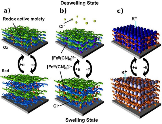
Figure 1. Electro-swelling processes of LbL films. Electro-swelling/deswelling of LbL films based on (a) redox active moieties grafted onto one of the polyelectrolytes, (b) free redox active molecules confined in LbL films, and (c) redox active component-based film. Reprinted with permission from [15], copyright (2015) Elsevier.
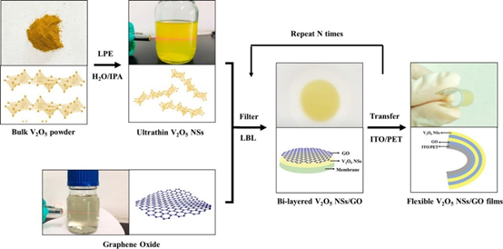
In a recent study on the fabrication of a flexible electrochromic display, Qi et al. demonstrated the formation of 2D composite materials consisting of V2O5 nanosheets and graphene films using the electrostatic LbL method, as shown in Figure 2a. The composites exhibited an impressive ultrafast response time in coloring and bleaching because of the reduced agglomeration, improved electronic conductivity, and reduced charge transport distance, as shown in Figure 2b [37]. When the endurance of the device was tested by bending at an angle of 90° for 100 cycles, rapid electrochromic response time was still observed. This shows that the EA method possesses excellent potential for the future development of flexible devices.
 |
|
(a) |
 |
|
(b) |
Figure 2. (a) Schematic illustration of the LbL assembly process of flexible V2O5 NSs/GO@ITO/PET films. (b) Schematic illustration of the coloring and bleaching processes of V2O5 NSs/GO films. Reprinted with permission from [37], copyright (2020) Elsevier.
2.2. Composite LbL Films for Biomedicine and Biomimetic Extracellular Matrix
In the early stage of LbL development, most studies focused on the use of synthetic polyelectrolytes. However, when considering the application of EA and LbL techniques for biomedical and biomaterials applications, researchers began to focus on the use of natural polyelectrolytes such as chitosan, dextran, amine hyaluronic acid, heparin, etc. [6]. The use of natural polyelectrolytes in LbL assembly provides a new potential for the development of advance structural composites with precise design such as core–shells for drug delivery. Furthermore, the flexibility of post-treatment after LbL assembly is an added advantage, especially for altering the physicochemical properties of the assembled composite films. Parameters such as temperature, light irradiation, electric field induction, pH adjustment, and vibrational stimulation can be used to adjust the properties.
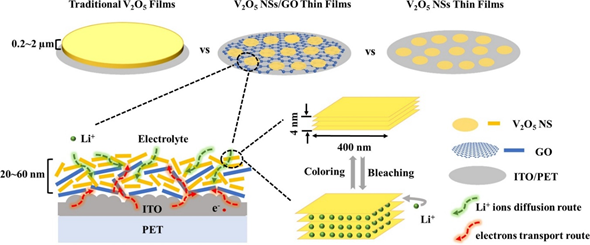
For the functionalization of biomaterials, it is important to create a microenvironment that mimics the extracellular matrix [17]. By designing polymeric LbL films, current progress has enabled the development from only mimicking cell configuration to the possible control of cell behaviors [16]. The possibilities of biochemical engineering via the EA method is vital for the advancement in biomaterials and tissue engineering fields [17]. Due to the good stability of electrostatically assembled films in aqueous solution and its dynamic potential, the microenvironment generated, which is almost equivalent to the natural cellular matrix, is crucial due to the cells’ selective recognition to certain biochemical and biophysical conditions. Liu et al. have demonstrated protein immobilization through matrix binding via the LbL technique. As shown in the schematic in Figure 3, the immobilization of a chemoattractant known for hematopoietic stem cell homing and cancer progression called stromal cell-derived factor-1 (SDF-1α) was achieved using poly(l-lysine) (PLL) and hyaluronan (HA) polyelectrolytes using the LbL process. This resulted in a significant increase in human epithelial breast cancer cell spreading in the matrix-bound SDF-1α. From their investigation, they found that the cell adhesion on films with matrix-bound SDF-1α exhibited an obvious spatial organization with good focal adhesion compared to the cells presented with a soluble cue [38]. Their study showed that LbL films were effective as a biomimetic tumoral niche in revealing potent cellular effects as well as underlying mechanisms that can be useful for the research in regenerative therapies against cancer cells such as breast cancer.
Figure 3. (A) Successive steps for the preparation of matrix-bound stromal cell-derived factor-1 (SDF-1α) using layer-by-layer films as extra-cellular matrix with poly(l-lysine) (PLL) and hyaluronan (HA) as polyelectrolytes. The film is first deposited step-by-step (1), then cross-linked (2) and finally loaded with SDF-1α in acidic conditions (1 mM HCl) (3), followed by a rinsing step in order to obtain matrix-bound SDF-1α (4). (B) SDF-1α can be presented as a soluble cue (sSDF) or in a matrix-bound manner (bSDF). Reprinted with permission from [38], copyright (2017) Elsevier.
2.3. Composite Materials for Energy Storage and Conversion Technologies
Recent development in the Internet of Things and electric vehicles has resulted in a demand surge for composite materials with high storage and energy capacity. Electrochemical energy storage systems such as lithium-ion batteries, lithium-sulfur, and metal–air batteries have attracted attention due to their high specific energy capacity [8,39,40]. In a recent study carried out on all-solid-state lithium–sulfur batteries, Phuc et al. reported the use of the EA method in the design of their solid electrolyte consisting of 0.67 Li3PS4–0.33 LiI (LPSI) and sulfur–carbon nanofiber (S-CNF) using a novel liquid phase route [40]. The schematic for the preparation of the S-CNF via the EA method is shown in Figure 4a–c, while Figure 4d shows the SEM image and energy-dispersive X-ray (EDX) mapping of the S-CNF–LPSI composite. The proper distribution of S-CNF within the LPSI promoted an electrically conductive pathway to overcome the LixSy electronic insulation behavior, enabling a good lithium–sulfur battery performance. In the development of Fe–air batteries, Tan et al. reported a facile and simple way to decorate iron oxide particles (Fe3O4) at room temperature on carbon paper in a short period of 10 min using the EA method. The Fe3O4-decorated carbon paper was used in the evaluation of alkaline aqueous and all-solid-state Fe-air batteries with a maximum discharge capacity of 460 and 70 mAh g–1, respectively [41].
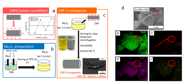 |
Figure 4. Schematics of sulfur–carbon nanofiber (S-CNF) composite preparation: (a) adjustment of the CNF surface charge, (b) formation of Na2S3 solution, (c) S-CNF composite formation. The SEM image and and energy-dispersive X-ray (EDX) mapping results for S, C, P, and I of the S-CNF−LPSI (Li3PS4–0.33 LiI) composite are shown in (d). Reprinted with permission from [40], copyright (2020) ACS.
As 2D graphene-derived materials are becoming an integral part of the materials used in the development of advanced functional composites, they have been incorporated in various composites for a wide range of applications [42]. The application of the EA method for the integration of graphene materials into composites has been reported in the literature. For supercapacitor applications, Fenoy et al. reported on the fabrication of electrode materials using electrostatic assembled polyaniline–PSS complex layer with iron oxide nanoparticles decorated graphene layers in aqueous solution [11]. They demonstrated an excellent electrochemical capacitance of 768.6 and 659.2 F g−1 in 0.1M HCl and 0.1M KCl (at 1A g−1), respectively with high cycling stability up to 1600 cycles. In another interesting development, a possible diffusion-driven mechanism of LbL assembled layers was reported by Hong et al. They demonstrated the formation of a porous reduced graphene oxide (rGO)/polyaniline (PANI) composite as the binder-less electrode for supercapacitors [43]. The strong electrostatic interaction between graphene oxide (GO) and the branched polyethyleneimine after the diffusion process enabled the formation of a porous foam-like structure as a template for the polymerization of PANI, as shown in Figure 5. This simple fabrication of a binder-less electrode yielded a capacitance performance of 438.8 F g−1 at 0.5 A g−1 in 1 M H2SO4.
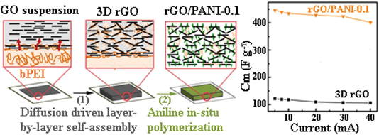
Figure 5. Schematics of preparing reduced graphene oxide (rGO)/PANI (polyaniline) composite film. Branched polyethyleneimine (bPEI) solution was coated on a filter paper. The coated paper was immersed in assembly graphene oxide (GO) suspension. GO and bPEI formed a stable complex layer at first. Then, bPEI diffused out of the reservoir and complexed with GO sheets. This complexation and diffusion process continued, eventually developing into a thicker GO/bPEI composite film. Some square GO/bPEI films (2 × 2 cm2) were cut and detached from the substrate, then subjected to a hydrothermal treatment at 190 °C. Finally, the hydrothermally reduced-GO films were used as a template for the polymerization of aniline. The rGO/PANI exhibits capacitance of 438.8 F g−1 at 0.5 A g−1 in 1 M H2SO4. Reprinted with permission from [43], copyright (2017) Elsevier.
For fuel cell applications, proton exchange membrane fuel cell (PEMFC), which possesses a high energy conversion efficiency and low-cost fabrication, is an alternative source for a clean energy [44]. Currently, researchers are working on the development of PEMFC due to its higher reaction kinetics and easier heat management. Current challenges include obtaining a polyelectrolyte membrane (PEM) that exhibits good proton conduction at elevated temperature and low humidity [45]. In order to obtain a higher phosphoric acid uptake to promote higher proton conductivity, the formation of organic–inorganic hybrid membranes to improve the physico- and electrochemical properties of the PEM were reported [46–48]. Using the EA assembly, controlled multilayer LbL membrane formation enabled the fabrication of PEM with desired properties such as improved proton conductivity and mechanical property [45,49]. Che et al. reported the formation of multilayer-component PEM using sulfonated polyetheretherketone (SPEEK) as a polyanion while polyurethane (PU) and the ionic liquid of 1-butyl-3-methylimidazolium were used as a polycation, as shown in Figure 6. The films obtained as shown in Figure 6 had a thickness of approximately 25 µm after 100 layers of coating, and the films exhibited satisfactory mechanical strength and excellent conductivities with different phosphoric acid doping levels [45].
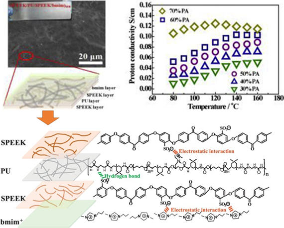
Figure 6. Multi-component membrane of SPEEK–PU–SPEEk–bmim obtained via the LbL method, which demonstrated a maximum proton conductivity of 1.03 × 10⁻¹ S/cm. Schematic of the interaction force between SPEEK and PU, SPEEK and bmim+ in one layer of the LbL membrane. Reprinted with permission from [45], copyright (2019) Elsevier. PU: polyurethane, SPEEK: sulfonated polyetheretherketone, bmim: 1-butyl-3-methylimidazolium.
2.4. Composite Materials for Additive Manufacturing
Additive manufacturing (AM) technology is regarded as the next-generation manufacturing revolution that would enable the rapid and moldless formation of complicated components [50–54]. The potential of AM is massive for the production of functional composites from a wide range of materials such as metals, polymers, and ceramics. AM enables the rapid prototyping and transformation of product manufacturing with precise customization. The synchronization of computer–aided design with AM has enabled the formation of complex 3D structures within a short time with maximum material utilization while enabling flexible customization and design. According to Tofail et al., AM is close to being a “bottom–up” manufacturing process, where the desired structure is fabricated using a “layer-by-layer” approach, resulting in unprecedented freedom in the manufacturing processes [52]. In AM 3D printing technology, the ability to sinter the materials via indirect and direct laser sintering of the printed artifact is one important factor for rapid prototyping. Although breakthroughs have been reported for metal and polymeric materials, laser sintering of ceramics remains a challenge due to their high melting point, poor thermal shock resistance, poor ductility, and limited laser absorptivity [55,56]. In the work reported by Kuwana et al., cellulose nanofiber (CNF) decorated alumina (Al2O3) powders obtained via EA were used as a composite for the selective laser sintering of Al2O3 [32]. The EA method enabled the homogeneous adsorption of CNF onto Al2O3 particles, which were converted to carbon residue after the heat treatment to allow improved laser absorption for the sintering process. The feasibility of using naturally abundant CNF in materials design also promotes sustainability for AM. In another recent work, Yavari et al. studied additive manufactured bio-functionalized meta-biomaterial composites with infection prevention and bone tissue regenerative properties [57]. The LbL coating was carried out using gelatin- and chitosan-based coatings containing either bone morphogenetic protein (BMP)-2 or vancomycin on the surface of selective laser melted porous structures made from commercial pure titanium, as shown in Figure 7. This study unequivocally demonstrates that multifunctional additive manufactured composite materials can be fabricated using the EA method.
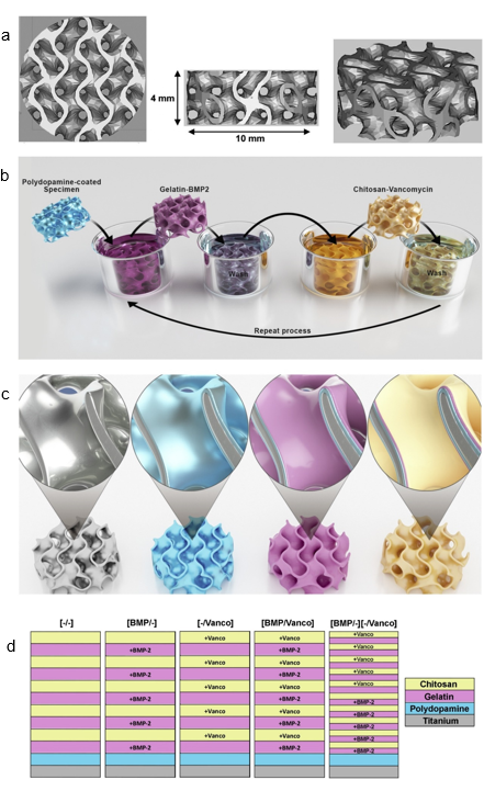
Figure 7. Computer-aided design drawings of the porous structured titanium used as input for the AM process (a). Schematic illustration of the layer-by-layer coating process (b,c) and the resulting surface layers (d). Reprinted with permission from [57], copyright (2020) Elsevier.
2.5. Ceramic Composites
2.5.1. Mechanical Properties Control of Carbon-Based Al2O3 Composites
Carbon-based Al2O3 composites have attracted attention due to their exceptional mechanical properties such as failure strength, toughness, and wear resistance [58]. In addition, other properties such as the electrical and thermal properties of these composites can also be altered [59–61]. By using the EA method to control the decoration of carbon additives on Al2O3, the mechanical properties of carbon–ceramic composites can be achieved. In a recent study that used microparticles of Al2O3 granules with adsorbed carbon nanoparticles (CNP) on their surface, Tan et al. demonstrated that by controlling the amount of CNP additives and Al2O3 microparticle size, different surface coverage could be obtained. This led to a controlled microstructure formation with controllable mechanical properties. The good homogeneity of CNP decorated on Al2O3 particles played an important role in the formation of an interconnected carbon layer along the Al2O3 boundaries influencing the final mechanical properties, as shown in Figure 8 [30]. The controlled amount of CNP decoration at the grain boundaries influenced the hardness of the composites, which was determined by an indentation test.
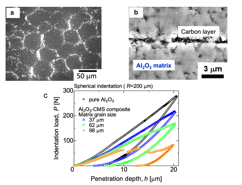
Figure 8. (a) Microstructure of 0.6 vol% carbon nanoparticles (CNP)–Al2O3 composite using Al2O3 with the average diameter of 62 μm. (b) Grain boundary of CNP–Al2O3 composite. A carbon layer could be observed at the interface between the Al2O3 matrix. (c) Hysteresis curves of indentation load and penetration depth of 1.0 vol% CNP–Al2O3 composites. Reprinted with permission from [30], copyright (2019) Springer Open.
2.5.2. Porous Ceramic Composites
Porous ceramic materials with controllable microstructures possess a good potential for applications such as heat insulation, sound dampening, bio-ceramics, and as catalyst carriers for lightweight structural components [55,62,63]. In the fabrication of porous ceramic materials, various methods such as sol–gel, freeze-casting, the addition of a pore-forming agent, and partial sintering methods are employed [64,65]. However, the achievement of a controlled homogenous distribution of the porous structure remains a challenge, especially when more than one elemental material is used in the composite mixture. The use of the EA method to control the formation of a porous ceramic material consisting of Al2O3 and silica (SiO2) without the use of pore-forming agents has been recently reported [10]. By changing the volume percent of SiO2 particles addition, which affects the coverage percentage of SiO2 on the surface of Al2O3, the control of microstructure formation, open porosity, as well as the mechanical properties of the sintered Al2O3–SiO2 composite ceramics were demonstrated.
2.5.3. Translucent Ceramic Composite Films with Controllable Optical Properties
In ceramic film formation, thermal spraying and chemical vapor deposition are commonly used. Due to limitations such as expensive equipment and the thermal stability of substrates, researchers have opted for a more rapid and low-temperature ceramic film fabrication method [66,67]. The feasible formation of compact ceramic films by aerosol deposition (AD) was discovered by Akedo, and since then, this method has been used for various types of ceramic film fabrication [58,67–71]. The advantages of the AD method are the rapid ceramic film formation rate and the feasibility of room temperature impact consolidation (without heat treatment) [66,67,72,73]. To deposit composite ceramic films with good transparency and desired optical properties, a homogeneous mixture of starting materials is indispensable. Therefore, electrostatic assembled composite powder can be used to obtain the desired optical properties of aerosol-deposited ceramic films [31]. With a homogeneous decoration of indium tin oxide (ITO) or cerium oxide (CeO2) nanoparticles on Al2O3 as shown in Figure 9, tailoring of the ultraviolet and infrared light adsorption properties of transparent Al2O3 composite films have been recently reported [31]. As shown in the schematics in Figure 9, inhomogeneous powder mixtures with agglomeration will affect the film deposition uniformity, thereby causing the property deterioration of the AD films as compared to electrostatically assembled composite powders.
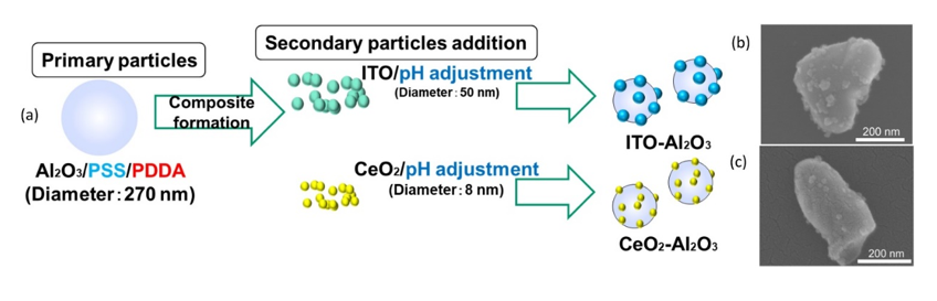
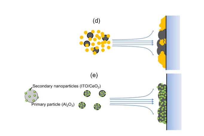
Figure 9. (a) Schematics of the ITO–Al2O3 and CeO2–Al2O3 nanocomposite formation via an electrostatic adsorption method while (b,c) are the SEM images of the as-obtained ITO–Al2O3 and CeO2–Al2O3 nanocomposites, respectively. The schematic of aerosol-deposited films using (d) mixed oxide nanoparticles and (e) homogenous electrostatically adsorbed nanocomposite oxide particles. Reprinted with permission from [31], copyright (2019) Elsevier.
2.6. Controlled Properties of Poly (Methyl Methacrylate) (PMMA) Composites
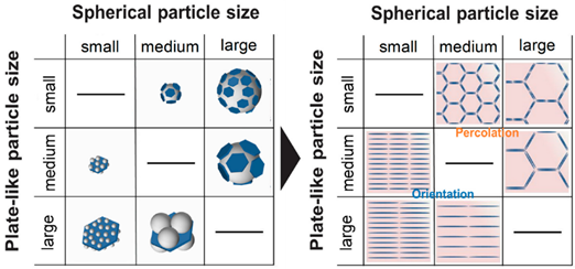
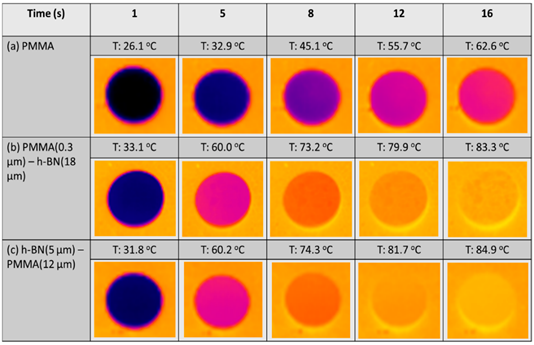
In the design of lightweight and portable devices, advanced polymer composites with desired properties such as good heat conduction, electrical conductivity, and controlled optical properties are indispensable. The fabrication of high-performance polymer composites by controlling the homogeneity and distribution of the organic and inorganic material composition is one of the important factors for achieving desired properties without compromising the mechanical properties [33,35]. Among the polymeric matrix materials available, poly (methyl methacrylate) (PMMA) is a well-known material due to its good optical clarity, mechanical strength, and thermal stability; they are said to possess the potential to replace glass in various applications [9,74]. By using the EA method, the homogenous distribution of functional materials within the PMMA matrix has been reported to enable the generation of desired and unique properties in PMMA matrix composites [8,35,75–77]. In a recent study, Yokoi et al. demonstrated the controllability of the thermal conductivity of hexagonal boron nitride (hBN)/PMMA composites by either adjusting the sizes of the hBN sheets or the particle size of PMMA particles used in the EA process [8]. Interestingly, the controlled decoration of hBN sheets within the PMMA matrix led to either the percolation of hBN or a layer-oriented microstructure demonstrating the different heat conduction behaviors, as shown in Figure 10. On the other hand, in a different application of infra-red (IR) filtering, Tan et al. reported the homogeneous decoration of nano-sized ITO particles within the PMMA matrix in the fabrication of IR filtering PMMA–ITO composite pellets [9]. Precise control of the amount and decoration of ITO within the PMMA matrix is a crucial factor in maintaining the visible light transmission within the composite [78,79]. A good distribution of ITO nanoparticles within the matrix would generate a 3D-ITO framework creating plasmonic responses as well as electric field coupling that results in the IR ray reflectivity for filtering effect generation [80–82].
 |
|
(A) |
 |
|
(B) |
Figure 10. (A) Schematic illustrations showing the composite morphologies of hexagonal boron nitride (hBN)/poly (methyl methacrylate) (hBN/PMMA) and PMMA/hBN composite particles with the corresponding microstructures obtained. (B) Thermograph images of (a) PMMA, (b) PMMA (0.3 µm)/hBN (18 µm), and (c) hBN (5 µm)/PMMA (12 µm) composite pellets after infrared thermography irradiation. Reprinted with permission from [8], copyright (2020) MDPI.