Interest in magnesium alloys and their applications has risen in recent years. This trend is mainly evident in casting applications, but wrought alloys are also increasingly coming into focus. Among the most common forming processes, forging is a promising candidate for the industrial production of magnesium wrought products. This overview is intended to give a general introduction into the forging of magnesium alloys and to help in the practical realization of forged products. The basics of magnesium forging practice are described and possible problems as well as material properties are discussed.
- magnesium alloys
- forging
- magnesium forging
1. Introduction
In general, forgings have better mechanical properties than cast parts and show favorable microstructural flow in loading direction if produced appropriately. This originates from a reduction of casting defects, closing of pores, refinement and breaking of primary phases as well as grain refinement and material flow while forming. Forgings are thought to show the best overall mechanical properties of all Mg products [27][1]27.
The use of Mg alloys in light-weighting shows its benefits particularly in bending applications where substantial increases in stiffness, strength and reduction of instabilities are possible with equal part weight. When heavier metals are exchanged for Mg alloys, it can be beneficial to modify the geometry, but this is not always necessary. Often, the part has already been designed in a way that the originally used material can be substituted directly with Mg alloys without a critical degradation in mechanical properties [27][1].
2. Alloy Designations
To describe the chemical composition of an alloying system or an alloy, designation systems are widely used. While various such systems exist, the one preferentially used in scientific literature is the ASTM Standard Alloy Designation System (B951-11) and also this work uses this system.
The ASTM Standard Alloy Designation System consists of four parts, the principal alloying elements, which are defined by one letter each, are the first part. In the second part the rounded-off percentages (wt%) of the respective elements are given. The third and fourth parts are the number of standardization (starting with the letter A and omitting O and I) and the temper designation. Regrettably, the ASTM does not provide designations for all available alloying elements, therefore the designations used by the authors cited are adopted in this work. An overview of the most common alloying elements and the respective designations based on the ASTM system are given in Table 1 Tand a seblection of temper designations is presented in Table A2 in the Appendix B 1.
Table 1.
Common alloying element designations based on the ASTM Standard Alloy Designation System.
| Element | Element | ||||
|---|---|---|---|---|---|
| Designation | Name | Abbrev. | Designation | Name | Abbrev. |
| A | aluminum | Al | N | nickel | Ni |
| B | bismuth | Bi | P | lead | Pb |
| Ba | barium | Ba | Q | silver | Ag |
| C | copper | Cu | R | chromium | Cr |
| D | cadmium | Cd | S | silicon | Si |
| E | rare earth | RE/REE | T | tin | Sn |
| F | iron | Fe | V | gadolinium | Gd |
| H | thorium | Th | W | yttrium | Y |
| J | strontium | Sr | X | calcium | Ca |
| K | zirconium | Zr | Y | antimony | Sb |
| L | lithium | Li | Z | zinc | Zn |
| M | manganese | Mn | |||
3. Forming Behavior
The forming behavior and suitability of Mg alloys for forging processes can be investigated with a multitude of tests, the most common are tensile and compression (upset) testing and also backwards extrusion.
Compression, upsettability or upsetting tests can be conducted with a multitude of testing parameters (e.g., temperature, strain rate, etc.) and sample shapes. The resulting deformation of the sample is controlled by lubrication, die design, sample shape and material behavior [28][2]. Most commonly, testing is done on a cylindrical billet between two flat dies. The billet is compressed till either cracks appear or to a predefined strain. Thereby, the forming behavior, possible surface defects and necessary deformation force can be measured directly. The microstructure and (depending on the sample size and analysis method) the mechanical properties of the deformed samples can be analyzed as well.
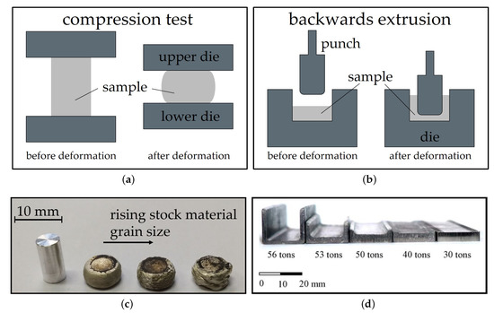
Backwards extrusion is a relatively simple testing set-up that can be implemented both experimentally and by simulation. The material is pressed into a die by a punch and the layout leaves space for the compressed material to flow into the opposite direction of the punch. Thereby a cup or a comparable form is shaped. The height of the walls of the part is dependent on the material flow behavior, lubrication and used forming load. In terms of complexity, backwards extrusion can be considered an intermediate step between compression testing and more complex die forgings. Compared to compression testing, backwards extrusion testing accomplishes higher degrees of deformation, higher hydrostatic stresses and exhibits a more complex material flow. The testing schemes and sample shapes for compression testing and backwards extrusion are depicted in Figure 2.

Figure 2. Schemes of simplified testing set-ups for (a) compression testing and (b) backwards extrusion; (c) AXM lean alloy compression samples with varying stock material grain sizes tested at 400 °C. Picture (d) shows parts manufactured from AZ31 by backwards extrusion at 250 °C with varying forming load [29][3], reproduced with permission from Elsevier.
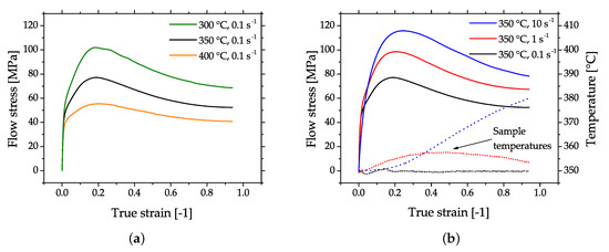
The flow behavior of Mg alloys in compression testing is characterized by softening after reaching the peak stress. Microstructurally, this behavior is due to dynamic recrystallization (DRX) which it is the most beneficial deformation mechanism for a successful forming of Mg parts. In case of higher forming speeds the flow stress usually increases, but this can be mitigated by an increase of the material temperature which causes a decrease in flow stress. A typical example of this behavior is given in Figure 3, where flow curves of cast and homogenized (425 °C for 24 h) AZ31, measured by cylindrical compression tests are shown.

Figure 3. Flow curves of cast and homogenized AZ31, obtained by cylinder compression testing. The plots show the flow stress (full lines) of samples tested with (a) varying temperatures and (b) varying strain rates. The dotted lines in (b) show the increasing sample temperatures with increasing strain rate. No temperature compensation was done for the shown flow stress values.
When tensile testing is applied to layout a process, it is important to take into account that the necessary forging pressure might exceed the tensile strength by far [26][4]. Although Mg parts can be formed by hammer forging, die forging with hydraulic presses is commonly used. The main reasons for this are the reduced ductility, increased flow stress and cracking sensitivity at higher forming speeds (occurring in hammer forging). Mg alloys, like many other materials, show improved forming behavior in case of increased hydrostatic stresses, because free surfaces are especially prone to cracking while forming. Therefore, a closed-die process facilitates optimal forging conditions.
4. Forging Stock
The stock material should be well homogenized to disperse eutectic phases and it should exhibit a small grain size, as grain size is a main aspect of the forming behavior in Mg alloys besides temperature and forming speed [30][5]. Cracking of Mg parts with coarse grains can be easily seen in the case of higher forming speeds, for example, in the behavior of the flash. Therefore, it is not surprising that often pre-deformed stock (mainly extruded) is used for forging. It is well known that extruded Mg has a high degree of anisotropy, which strongly influences the flow behavior during forging as well as the mechanical properties in the finished part. This can be taken into account by providing increased deformation into the transverse direction, thereby improving the usually low transversal ductility [26][4].
5. Die Design
The die design used for Mg alloys is comparable to that applied for Al alloys. If the same dies are used, the differing processing parameters and thermal expansion coefficients might result in slightly different part sizes at room temperature (RT). Depending on the alloy it might be necessary to use additional forming steps for Mg. To achieve a good surface quality of the forged parts, the dies should have a smooth surface, which also eases metal flow while forming [30][5]. Magnesium can only be forged at elevated temperatures; the dies should therefore be made of materials with sufficient high-temperature strength. According to Behrens et al. [31][6], 1.2344 (X40CrMoV5-1), 1.2365 (32CrMoV12-28), 1.2367 (X38CrMoV5-3), 1.2714 (56NiCrMoV7) as well as other conventional low-alloy hot-work tool steels are commonly used [30][5]. For layout purposes a number of recommended radii for corner and fillet of Mg forgings are listed in Reference [27][1].
6. Temperature Control
Temperature control of the billet and the dies is essential in the forging process. While forging usually takes place well below the melting temperature and, therefore, fire hazard is greatly reduced, care has to be taken to avoid excessive overheating and hot spots while heating the material. The billets should be heated uniformly to achieve good forging results and avoid failures like shear or hot cracking [30][5]. The temperature of the forging stock depends on the material used (alloy, as-cast, homogenized or extruded) but also on the die temperatures, forming speed, billet shape and size, number of applied forging steps and degree of deformation. These factors all play a role when looking at the forming window of a product; other criteria might be mechanical or microstructural properties. The die temperatures can either promote underfilling or surface cracking if too hot or cold, respectively [26][4]. Controlling the forging temperature is also a way to influence the grain size of the produced part. To keep the grain size small, the forming temperature can be reduced in each forging step. Magnesium alloys are known for static recrystallization after deformation; to prevent this, the finished parts can be quenched in water. An overview of frequently used stock and die temperatures according to Reference [30] is given in Table A3 in the Appendix B.
7. Lubrication
Lubrication is an important part of every forming practice. For Mg forgings graphite-oil or graphite-water suspensions are usually used, depending on the die temperature. For higher temperatures oil-graphite suspensions are suitable. In all cases the carrier fluid evaporates from the heated dies and a thin graphite film remains on the surface [30][5].
According to the study on lubricants on AZ80A, conducted by Shaw et al. [25][7], very good results have been achieved with both, as well as with a mix of graphite and powdered MoS22in water. For a further improvement of penetration into die cavities not only the dies can be lubricated but the stock material as well. This is realized by vapor blasting or etching (using acetic acid) of the billet and a subsequent dipping into the lubricant before heating it to forming temperature. According to Sabroff et al.[4] [26] care should be taken to keep the flash regions—where friction is desired—free of lubricant.
8. Trimming
Trimming of forged Mg parts can be either done at the minimum forging temperatures or the flash can be removed by sawing at room temperature (RT). Warm trimming might pose some problems with bending or warping of the part, therefore this is only done if the flash regions are sturdy enough. Flash removal by band saw at RT is common if only small quantities of parts are produced. Mg-alloys often show brittle fracture behavior in case of trimming at room temperature using a trimming press [26,30][4][5]. In some cases, parts might then be ruined as the brittle fracture of the flash extends into the part itself.
9. Machining
According to Reference [27][1], Mg alloys can be machined easily with or without lubricants (coolants) at high speeds. Compared to other structural metals like Al, the tool wear and power required for machining is reduced and the parts obtain a smooth finished surface. Lubricants (mineral oils) are mainly used as coolants to decrease possible part distortion and chips ignition. Increased risk of fire can be the case if cutting speeds over 5 ms-1 are applied and feeds are smaller than 0.2 mm. Fine cuts produced by finishing might also be ignited by sparks if handled improperly.
10. Microstructure and Mechanical Properties
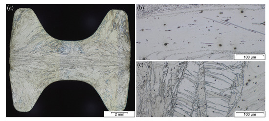
The microstructure and subsequently the mechanical properties of Mg forgings can vary excessively within a part. The final microstructure depends on temperature, degree of deformation and forming speed. It might be composed of twinned grains, fine recrystallized grains, necklace structures, shear bands and combinations thereof in the same part. This behavior is pronounced in as-forged parts. The example given in Figure 4 stems from a laboratory-scaled piston rod [32][8]. The varying degrees of deformation are well visible in the microstructure of the cross-section. In the sample center a combination of deformed and fine recrystallized grains, a so-called necklace structure, is present. On the sample rim, having a lower degree of deformation, large, heavily twinned grains are prevalent. In the case of a subsequent heat treatment or slow cooling of the parts, recrystallization progress depends on available energy and nucleation points, for example, twin and grain boundaries.

Figure 4. Microstructure of an AZ31 variation (AZ31 containing 0.3Ca and 0.2Y) in as-forged condition, formed at 425 °C stock temperature and 280 °C die temperature at a ram speed of 10 ms-1, showing (a) cross-section of forged part, (b) sample center, (c) sample rim.
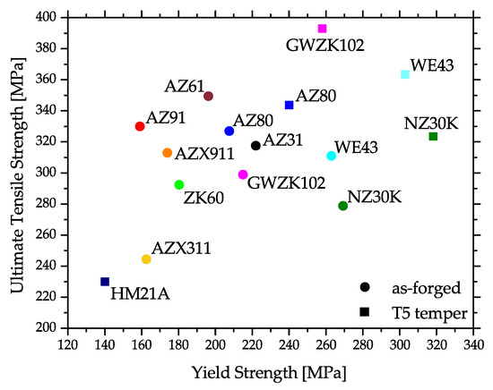
Corresponding to this behavior, the mechanical properties may differ considerably throughout the part. This is the case for strength properties, but especially for ductility, where the difference between twinned and recrystallized microstructure may be considerable. An overview of literature values of yield strength (YS) and ultimate tensile strength (UTS) values of various Mg alloys at RT is given in Figure 5. A more detaFiled sgummary is given inre 5. Appendix C, where tensile properties and process information is compiled.

Figure 5. Tensile properties of various Mg alloys, showing as-forged and artificially aged (T5) values at room temperature (RT). The graphic shows mean values calculated from various scientific sources. A more detailed overview is given in Appendix C.
11. Heat Treatments
Heat treatments for Mg alloys are similar to those known for other materials (i.e., Al). The well known steps of homogenization, solution heat treatment and artificial ageing, or a combination thereof, can be used for various alloys in the production of wrought Mg parts.
Some confusion might exist when looking at the parameters applied for heat treatments of Mg casting products, where the solution heat treatment can last for hours. This originates in the purpose of the heat treatment, which primarily aims to dissolve primary phases after casting. Adequate parameters (time and temperature) should also be used for wrought products in the homogenization heat treatment before forming. The solution heat treatment of wrought alloys, on the other hand, has a much shorter duration. This is the case because the alloying elements should already be well dispersed in the material and excessive grain growth of the usually fine grained and/or deformed microstructure should be avoided. While quenching is not necessarily done after homogenization it might very well be necessary after a solution heat treatment to prevent premature precipitation of hardening phases. Artificial ageing times and temperatures have to be adapted to the alloy used. Especially the ageing duration can vary excessively. For example, rare earth containing alloys may have ageing times of multiple days [33].
An overview of possible heat treatment temperatures and times for various alloys is given in Table A4[9].
References
- Nunes, R.; Adams, J. ASM–Handbook Volume 2: Nonferrous Alloys and Special-Purpose Materials; ASM International: Materials Park, OH, USA, 1992
- Dieter, G.E.; Kuhn, H.A.; Semiatin, S.L. Handbook of Workability and Process Design; ASM International: Materials Park, OH, USA, 2003.
- S.C.V. Lim; M.S Yong; Plane-strain forging of wrought magnesium alloy AZ31. Journal of Materials Processing Technology 2006, 171, 393-398, 10.1016/j.jmatprotec.2005.07.011.
- Sabroff, A.; Boulger, F.; Henning, H.; Spretnak, J. A Manual on Fundamentals of Forging Practice; Technical Report; Battelle Memorial Institute: Columbus, OH, USA, 1964.
- Nunes, R.; Abbas, I. ASM–Handbook Volume 14: Forming and Forging; ASM International: Materials Park, OH, USA, 1996.
- Bettles, C.; Barnett, M. Advances in Wrought Magnesium Alloys: Fundamentals of Processing, Properties and Applications; Elsevier, Woodhead Publishing: Cambridge, UK, 2012.
- Shaw, H.; Boulger, F.; Lorig, C. Development of Die Lubricants for Forging and Extruding Ferrous and Nonferrous Materials; Technical Report; Battelle Memorial Institute: Columbus, OH, USA, 1955.
- Papenberg, N.; Gneiger, S. Closed Die Forging of Mg-Al-Zn-Ca-Y Alloys. In Resource Efficient Material and Forming Technologies; Kawalla, R., Prahl, U., Moses, M., Wemme, H., Luft, J., Kirschner, M., Eds.; Trans Tech Publications Ltd.: Pfaffikon, Switzerland, 2018; Volume 918, pp. 28–33.
- S.K. Panigrahi; W. Yuan; Rajiv S. Mishra; R. Delorme; B. Davis; R.A. Howell; K. Cho; A study on the combined effect of forging and aging in Mg–Y–RE alloy. Materials Science and Engineering: A 2011, 530, 28-35, 10.1016/j.msea.2011.08.065.
