1. Photopolymerisation Techniques
The strategy of photopolymerisation is based on using liquid-state monomers/oligomers in the presence of a photoinitiator material, which can be polymerised via a photochemical reaction under radical, cationic or mixed-mode mechanisms during exposure to UV or laser irradiation, with a specific wavelength and curing depth
[1][2][25,43]. In addition, some materials can be included in the mixture resin, such as a diluent/solvent, particle and fibre. The performance of the 3DP using the photopolymerisation technique depends on the components, such as a light source, curing direction, build platform and resin tank. The light source can be xenon lamps, mercury arc lamps, LEDs or lasers. Several 3D printers use this technology in producing shape memory components, such as SLA, DLP, CLIP and LCD, which are discussed
[3][4] in this section [39,44].
1.1. Stereolithography (SLA)
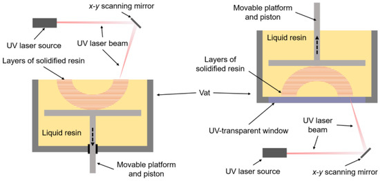
The SLA technique builds a 3D part by focusing a UV laser on the photopolymerisable resin to link the molecule chains
[5][6][40,45]. The apparatus consists of a vat containing liquid resin and a movable build platform (
Figure 1). The conventional apparatus layout has a UV source, an
x-
y scanning mirror over the resin and a platform that moves downwards as the UV laser beam locally cures the resin, i.e., photopolymerises the resin layer by layer. The inverted layout has a UV-transparent window on the bottom of the vat, and the UV source and the
x-
y scanning mirror are placed under the vat, the build platform moving upwards as the resin is locally UV cured layer by layer
[6][7][8][41,45,46]. The time required to print each layer relies on the UV laser beam speed and the irradiated area. These, in turn, are a consequence of a set of scanning mirrors, which reflect the laser beam along the
x-
y plane, photocuring the resin pixel by pixel, so that the surface of the photoreactive resin is sequentially exposed to the scanning laser beam
[7][8][41,46]. When completing printing, the object is pulled out from the remaining resin in the vat. It is cleaned with a cleaning agent, e.g., isopropanol, to remove any unreacted resin and then is subjected to a UV post-curing stage to improve the part’s final properties
[5][40].
Figure 1. Schematic of a typical stereolithography printing method.
For instance, researchers have already demonstrated the effective use of liquid-based resins consisting of photoreactive liquid and fillers, such as silver nanoparticles, copper powder, halloysite nanoclay, montmorillonite and fibres, employing these materials for SLA 3D printing
[9][10][47,48]. Furthermore, SLA has facilitated the advancement of 3D-printable stimuli-responsive materials, often utilising epoxy- and acrylate-based liquid resins
[11][12][13][14][49,50,51,52] that contain fillers, such as preformed polymeric particles
[12][50] or magnetic iron oxide nanopowder
[15][53]. Variations of SLA, such as mask image projection-based stereolithography (MIP-SL), projection micro-stereolithography (PµSL) and two-photon polymerisation-based printing (2PP), have also been employed within this context
[16][17][18][54,55,56].
1.2. Digital Light Processing (DLP)
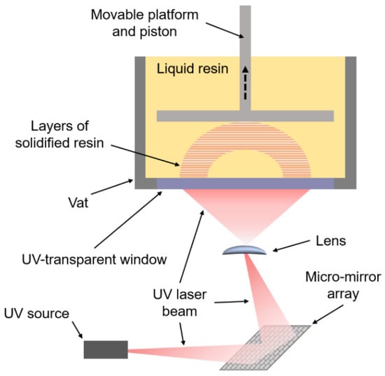
The DLP technique is a variation of SLA and differs from the latter as it can irradiate each whole layer at once, through a selectively masked light source, instead of having a laser beam that operates on a pixel-by-pixel basis
[8][19][20][46,57,58]. The equipment layout is very similar to an inverted SLA; however, instead of having scanning mirrors and a UV laser beam, there is a UV digital projector and a set of micro-mirrors (
Figure 2) that can simultaneously irradiate each pixel, which allows for the whole layer to be exposed at a single step and to cure at the same time as well
[8][19][20][46,57,58]. In this case, the time required to print each layer does not depend on the area to be printed, and the overall process speed is higher than that of SLA. The usage of DLP technology for stimuli-responsive materials has already been reported in the literature
[20][21][22][23][24][25][26][27][28][29][37,58,59,60,61,62,63,64,65,66].
Figure 2. Schematic of a typical DLP printing method.
1.3. Continuous Liquid Interface Printing (CLIP)
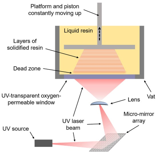
CLIP arises as a development from the DLP system, having the same irradiation technology, but allowing the part to be built uninterruptedly with a continuous liquid surface, i.e., the build platform is constantly moving rather than stepwise, as in conventional vat photopolymerisation techniques (
Figure 3). This behaviour leads to avoiding layer separation and recoating so that the printing process is claimed to be even faster, as there is no need to pause it between each printed layer
[7][30][31][32][41,67,68,69]. The main advantage of CLIP is the polymerisation inhibition due to the oxygen content in the dead zone, causing the partially consumed reagents at the bottom region of the solid to behave like a living polymerisation system as the liquid interface is continuous
[33][34][70,71].
Figure 3. Schematic of a typical CLIP printing method.
In this method, the UV laser beam irradiates the bottom of the vat, projecting the cross-section of the part to be printed; the cross-section projection is continuous and changes progressively like a film instead of launching each layer at a specific time. The printed component is continually moved up, allowing enough time for the photosensitive monomers to react and for the liquid resin to flow underneath the last cured resin portion
[35][36][72,73]. This behaviour produces a “dead zone”, i.e., a permanent liquid interface between the solid and the UV-transparent window, where, due to an oxygen-permeable membrane placed beneath the resin, the monomer is prevented from reacting as a consequence of the higher oxygen concentration
[33][34][70,71]. Regarding liquid-based pastes, Ware and Sun (2019) reported the formulation of ceramic-loaded composite inks consisting of photoreactive resin and hydroxyapatite nanoparticles, which were printed through micro-CLIP
[37][74].
1.4. Liquid Crystal Display (LCD)
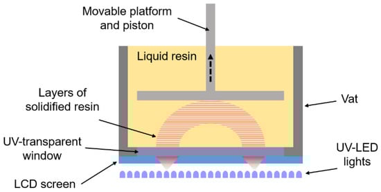
Further development from DLP has led to LCD-based stereolithography. In this method, the micro-mirror and lens set is replaced with an LCD screen powered by UV-emitting LEDs. These, like DLP, can irradiate or suppress each pixel; therefore, as the LEDs project the part’s cross-section, the liquid crystal screen launches this projection through the UV-transparent window to the resin in the vat
[38][75]. The LCD-SLA also allows the whole layer to be exposed at a single step and to cure simultaneously, building the part layer by layer (
Figure 4). Employing LCD-SLA for shape memory 4D-printed polymeric resins has effectively proved the ability of this technique to print high-quality 4DP components
[39][40][76,77].
Figure 4. Schematic of a typical LCD printing method.
2. Material Jetting Techniques
In contrast to vat photopolymerisation 3D printers, material jetting technologies enable one to print different polymer materials in a single process, offering, for instance, the possibility to change colours, formulations or fabricate parts that have specific features localised at different positions
[41][42][78,79]. In the case of photopolymers, material jetting relies on depositing droplets of liquid photoreactive resin on an
x-y plane, which are immediately irradiated by a UV laser to initiate polymerisation at that spot and prevent material waste, by-products and debris
[43][44][45][46][80,81,82,83]. These technologies evolved from single-layer 2D-printing techniques; hence, the three-dimensional part is built as ink deposited layer by layer
[44][45][47][81,82,84]. The MJ printer jets at least two materials, i.e., build material and support material
[48][85]. After printing, the jetted materials will be immersed in a solution to dissolve the support material. Some technologies, such as Stratasys’ polyjet or 3D Systems’ multijet printing, use an additional layer-levelling process before curing
[49][50][51][86,87,88]. It should be noted that polyjet and multijet printing are trademarks representing MJ technology. The two common sorts of 3DP liquid-based jetting materials are CIJ 3D printing and DoD 3D printing.
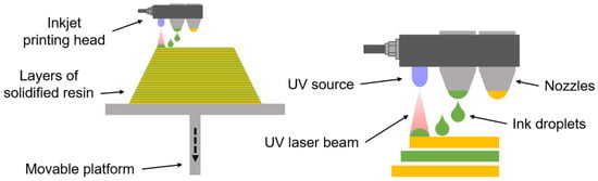
2.1. Continuous Ink Jetting (CIJ)
CIJ comprises a printing head that ejects a photocurable ink onto a substrate as an accurate
x-
y coordinate system leads the droplets to be deposited at specific locations. The printing head has a UV-emitting source and one or more nozzles (
Figure 5), each nozzle delivering a continuous jet of ink that readily splits into droplets and is subjected to UV-photoinitiated curing to coalesce once they reach the substrate
[44][45][52][81,82,89]. This jet splitting would naturally be random, causing the droplets to have varying sizes; nevertheless, applying a piezoelectric transducer that generates periodic mechanical oscillations can correct and control the stream
[53][90]. As the droplets exit from the nozzle, they are electrostatically charged. The amount of charge is associated with the corresponding pixel on the image to be printed. Thus, an electric field is applied to deflect the droplet and guide it to a specific position where it should land on the
x-
y plane
[53][90]. However, an issue challenging the effective use of CIJ for 3DP functional materials is the undesirable charge repulsion effects that arise as charged droplets become closer. Phung and Kwon (2022) proposed a novel voltage-driving scheme for selective area coating applications to overcome that issue
[52][89]. In this sense, CIJ has promising potential for 4D-printed smart materials, including photopolymer-based composites reinforced with metallic nanoparticles and carbon nanotubes
[43][54][80,91]
Figure 5. Schematic of a typical CIJ printing method.
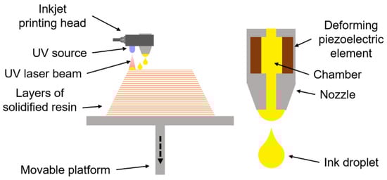
2.2. Drop on Demand (DoD)
Material jetting has been further developed into DoD technology. It differs from CIJ as the ink flow is fully controlled and released only when needed, i.e., on demand, instead of continuous jetting
[46][53][54][55][83,90,91,92]. The printing head nozzle contains a small reservoir or chamber where ink is stored while printing is not required, and two types of mechanisms can be employed to release an ink droplet, either piezoelectric or thermal (
Figure 6). In the former, piezoelectric transducers deform as they receive an electric pulse, squeezing the chamber and launching a droplet
[47][54][55][84,91,92]. In the latter, an electric pulse activates a thermal resistor that, within a timeframe in the order of microseconds, warms up the ink, producing an expanding bubble through rapid evaporation; hence, as the pressure in the chamber increases, the droplet is finally ejected from the nozzle
[47][53][54][84,90,91]. The piezoelectric inkjet exhibits an essential advantage over the thermal one, as the temperature rise represents considerable risk and could dramatically affect the product properties
[54][91].
Figure 6. Schematic of a typical DOD printing method.
Moreover, DoD possesses a broader range of photoreactive inks with varying properties since the electric pulse can be optimised to meet each ink formulation requirement. In comparison, CIJ is limited by a narrower range of viscosity and surface tension
[46][83]. DoD is suitable for processing materials that find applications in a number of different fields, including electronics, pharmaceuticals and, of course, rapid prototyping
[46][56][57][83,93,94].
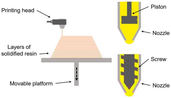
3. Material Extrusion Technique (Direct Ink Writing (DIW))
DIW is a 3DP technology similar to other extrusion-based AM techniques such as fused deposition modelling (FDM) (also called fused filament fabrication (FFF)), with a difference that in DIW, the printed material is not molten but rather it is semi-liquid or paste-like
[58][59][60][61][62][63][64][95,96,97,98,99,100,101]. In addition, DIW also differs from other material jetting techniques as it delivers continued material (
Figure 7) rather than splitting it into droplets, as in CIJ and DoD
[63][100]. In DIW, the material is released from a nozzle as the result of applied pressure, which can be generated either mechanically (through a rotary screw)
[61][62][63][98,99,100] or pneumatically (with a piston)
[63][64][100,101]. DIW is claimed to be able to deliver efficiently and accurately 3D-printed micro-lattice structures, as well as to possess one of the broadest ranges of rapid prototyping ink designs, making a vast number of possibilities feasible in terms of shapes and styles
[62][63][99,100].
Figure 7. Schematic of a typical DIW printing method.
Materials for DIW inks are often formulated to solidify immediately or shortly after they exit the nozzle and, frequently, they are subjected to a photocuring stage so that they harden, which can be performed simultaneously with the printing process or after fabrication
[60][63][97,100]. Furthermore, it is noteworthy that such inks typically present greater mechanical strength and can consist of highly viscous materials and fillers, such as organic or nonorganic particles, to impart shape retention after deposition
[61][63][98,100]. According to Yang et al. (2021), DIW inks should present high viscoelasticity before extrusion, exhibiting an excellent shear-thinning effect when moving through the nozzle and recovering the viscoelasticity after deposition to retain the desired shape
[61][98]. DIW faces challenges regarding the formulation of composite or functional inks that simultaneously possess the required shear thinning and modulus, as well as the ability to flow under shear stresses without issues and readily restore the previous viscoelasticity
[63][100]. Notwithstanding such matters of concern, DIW finds applications in several fields and has successfully been used to 3D-print mixtures of ammonium oleate with polymers, such as natural rubber, PVDF and epoxy resins
[61][98]; graphene-based paste for prototyping aerogels
[62][99]; cellulose nanocrystal paste
[64][101]; polycaprolactone-reduced graphene oxide composites
[65][102]; PLGA composites reinforced with calcium phosphate and graphene
[66][103]; and polymer-based hydrogels for biomimetic soft robots
[67][104].