In recent years, the motor has been increasingly used to replace the conventional gasoline engine for carbon emission reduction, and the high-performance motor is urgently required. The stator and rotor in a motor are made of hundreds of joined and laminated electrical steels. This paper covers the current research in joining the laminated electrical steels for the motor application, together with the critical assessment of our understanding. It includes the representative joining method, modeling of the joining process, microstructure of the weld zone, mechanical strength and magnetic properties. The gaps in the scientific understanding, and the research needs for the expansion of joining laminated electrical steels, are provided.
- electrical steel
- joining and welding
- microstructure
- magnetic property
- mechanical property
Please note: Below is an entry draft based on your previous paper, which is wrirren tightly around the entry title. Since it may not be very comprehensive, we kindly invite you to modify it (both title and content can be replaced) according to your extensive expertise. We believe this entry would be beneficial to generate more views for your work. In addition, no worry about the entry format, we will correct it and add references after the entry is online (you can also send a word file to us, and we will help you with submitting).
Definition
In recent years, the motor has been increasingly used to replace the conventional gasoline engine for carbon emission reduction, and the high-performance motor is urgently required. The stator and rotor in a motor are made of hundreds of joined and laminated electrical steels.
1. Introduction
As a machine to transform the electrical energy into mechanical energy, a motor has been widely used as the traction machine in industry equipment [1][2][3][4][5][6][7][1,2,3,4,5,6,7], e.g., electrical vehicle, electrical airplane, electric ship, and so on. Electrical steel [8][9][10][11][8,9,10,11], a high silicon (2–5.5 wt% Si) [12][13][12,13] and thin sheet (0.2–0.65 mm) steel [14], is the soft magnetic material for the stator and rotor in a motor [15][16][17][15,16,17]. The addition of silicon to iron results in a decrease in coercivity and an increase in resistivity [12][18][19][20][21][22][12,18,19,20,21,22]. Furthermore, the reduction of the sheet thickness results in the reduction of the eddy current loss in the electrical steel when put in the alternating magnetic field environment [14][23][24][14,23,24]. The stator and rotor in a motor are made of hundreds of laminated and joined thin electrical steel sheets [25], which could reduce the eddy current loss and improve efficiency. There are insulation coatings on both sides of the electrical steel sheet to cut off the interlaminar eddy current when hundreds of electrical steels are laminated in the motor application [26][27][28][29][30][31][32][33][34][35][36][26,27,28,29,30,31,32,33,34,35,36]. Generally, the goal of joining the laminated electrical steels is to ensure the mechanical strength of the laminations [37], while the joining process will lead to the degradation of the magnetic properties due to the damage of the insulation coating [38], the modification of the microstructure [39][40][39,40], the introduction of the residual stress [41], and so on. It is a great challenge to reach the trade-off between mechanical strength and magnetic properties [42]. Besides, the structure of the laminated electrical steels is different from the conventional lapped or butted sample, and the conventional knowledge about joining may not work for joining the laminations. Finally, it is important to study the joining of the laminated electrical steels, which could speed up the roadmap towards high-quality motor manufacturing.
2. The Representative Joining Method
Currently, the joining method for the laminated electrical steels could be generally categorized into three types: glue join [26][43][26,43], mechanical join [44] and fusion welding [45], as shown in Figure 12 [40]. The advantage of the glue-join method was that it did not destroy the insulation coating. Kaido et al. [26] measured the magnetic and mechanical characteristics of adhesive coating non-oriented electrical steel sheet cores in the conditions of motor and found that the deteriorations of iron losses and exciting currents by adhesion were less than those by welding. Schoppa et al. [46] coated the electrical steel laminations with the adhesive varnish, then the laminations were stuck together during a thermally activated process. Their experimental results showed that the increase of the specific core loss after sticking was very low, and they concluded that sticking was from the magnetic point of view one of the best methods of assembling laminations into magnetic cores. The glue-join method also allowed homogenous electrical isolation, reduced acoustic emission, and behaved high thermal conductivity in service [26][43][26,43]. Generally, the composition of the glue varies with the supplier, including the organic glue, inorganic glue and their combinations. However, the biggest obstacle for the large-scale application of this technique was the concern about the mechanical failure of the adhesion under the periodic load condition at an elevated temperature during the operation of the motor [47]. Besides, the cost was also higher than the other joining methods [46].
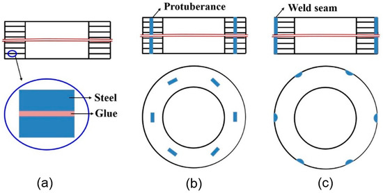
Figure 12. Schematic of the representative join methods for laminated electrical steels: (a) Glue join; (b) mechanical join; (c) fusion welding [40].
Both mechanical joining [44][48][49][50][44,48,49,50] and fusion welding [37][38][46][51][52][37,38,46,51,52] are widely used to join the laminated electrical steels at present. Senda et al. [44] compared the effects of two representative V-type mechanical interlocking methods, dowel formation and dowel jointing on the magnetic properties of the joined ring core sample made of the electrical steel laminations, they found that two methods showed comparable contributions to iron loss increase at low frequencies (e.g., 50 Hz), whereas, increases in iron loss due to dowel jointing were greater than those due to dowel formation at high frequencies. Imamori et al. [49] investigated the influence of interlocking on the magnetic properties of ring cores by measurement, and they observed that the inverse of permeability and iron loss increased linearly with the number of interlocks. The mechanical joining process is usually combined with the punching process in the progressive stamping die process. Finally, the cost of the mechanical joining process is a bit lower than that of the welding process. The disadvantage of the mechanical joining method is the lower strength at the direction perpendicular to the electrical steel surface compared to that of the fusion welded joint. Besides, the mechanically joined joint has a lower fatigue life under the periodic loads than that of the welded joint. In the case with the high strength requirement, several fusion welding passes were jointly used to enhance the strength of the mechanically joined sample.
The heat source used in fusion welding of the electrical steel laminations includes laser [37], electron beams [53], plasma arcs [39], electric arcs (TIG, GTA, CMT) [51][54][51,54], and so on. As a high efficiency and high-quality fusion welding method, laser welding was thought to be a potential method for welding of the electrical steel laminations in the high-performance motor application [37][40][42][51][55][37,40,42,51,55]. Compared to the other fusion welding methods, laser welding could achieve a smaller heat affected zone, induce lower residual stress, and finally obtain the welded electrical steel laminations with higher magnetic properties. Figure 23 shows the schematic of laser welding of laminated electrical steel laminations [40]. The moving energy beam melt the edge of the laminations continuously and the effective joint was formed at the interfaces of the laminations.
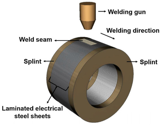
Figure 23.
Table 1 shows the representative research in the joining of laminated electrical steels. The critical factors affecting joining the laminated electrical steel laminations are as follows: (a) the special structure of the laminations made of hundreds of electrical steel sheets; (b) the insulation coating on both sides of the electrical steel sheet, which affects the dynamics of the molten pool during the fusion welding process because of the entrapped bubbles due to the pyrolysis of the coating and may induce pores in the weld seam; (c) the comprehensive requirement of the strength and magnetic property. The following sections will summarize the current research in joining of laminated electrical steels, which provides a better understanding of the joining process with great demands from the industry.
Table 1. Representative research in the joining of laminated electrical steels.
Joining method | Research content | Year | Reference | ||||||||||
Continuous laser welding | Strength: both the strength and the fatigue behavior of the weld material showed no appreciable | difference to the base material; | Microstructure: completely ferritic in both the base material and the weld seam; Defect: pores observed in the weld seam | 2014 |
[37] |
||||||||
Continuous laser welding | Model for torsion strength: mathematical model with the function to estimate the strength of the welded laminations based on the welding parameters | 2015 |
[56] |
||||||||||
Continuous laser welding | Strength of the welded ring stator: increase with the heat input; Microstructure ferrite in the weld seam; Magnetic property: deteriorate with the heat input | 2016 |
[40] |
||||||||||
Continuous laser welding | Simulation of temperature distribution: discontinuous temperature distribution in the heat affected zone due to the hinder of the interface | 2015 |
[47] |
||||||||||
Continuous TIG welding | Strength, microstructure, magnetic property: TIG welded joint has higher strength, coarser grain and worse magnetic property than laser welded joint | 2017 |
[51] |
||||||||||
Continuous welding | Magnetic property: mathematical model and FEM model were developed to estimate the eddy current loss | 2017 |
[57] |
||||||||||
Mechanical joining | Interlaminar eddy currents mainly affect the iron loss of the local zone. | 2017 |
[49] |
||||||||||
Glue | Mechanical property: critical adhesive shear angle values of about 5° were obtained for all laminate samples, independent of the steel substrates used to create the laminates | 2018 | [26] |
[26] |
|||||||||
Adaptive pulsed spot welding | Possibility of the adaptive pulsed spot welding for laminated electrical steels was proved. | 2014 |
[55] |
||||||||||
Statistical distribution of single welding spots | The strategy of distributed welding spot shows promising results to decrease the | magnetic deterioration, especially as an approach for higher | frequency applications | 2018 |
[42] |
3. Summary and Future Development
A comprehensive investigation about the effects of the joining process on the performance of the stator is required. The mechanical strength, fatigue life, and magnetic properties of the joined electrical steels are the indicators for the performance evaluation, especially the values of these indicators at an elevated temperature. Besides, the cost of each joining method also should be identified.
Much more work should be conducted to reveal the mechanism for magnetic properties degradation. The in-situ experiment may be a useful method to measure the magnetic properties of the joined electrical steels. For example, the temperature distribution in the joined electrical steels may be in-situ measured by the thermal imager [58][102], which could be used to validate the energy loss distribution in the electrical steels calculated by the thermal finite element model. The variation of the magnetic domain in the electrical steel at the external load condition under the alternating magnetic field environment may be in-situ measured by the neutron grating interferometry [59][103], magnetic force microscopy [60][104], magneto-optical indicator film [61][105], which could help understand the stress induced magnetic properties degradation.
Besides, there is still a huge space to optimize the process of joining the laminated electrical steels. More experiments could be conducted to build the relationship map between the process parameters and performance of the joined laminations, and the simulation model could help to understand the mechanism underlying the experimental phenomena.
In the current simulation model for welding of the laminated electrical steels, the birth and death element technique was adopted to describe the rapid increase of the thermal contact conductance when the interfaces between the laminations were melted due to laser irradiation. Though this method could characterize the effects of interfaces on the heat transfer during the welding process, the gap filling and residual stress evolution process still could not be analyzed. Finally, the thermal-mechanical-fluid coupled model will be developed to have an in-depth understanding of this welding process.
Most of the current research focused on evaluating the performance of the welded laminations, while did not reach the performance of the actual motor. The effects of the welding process on the performance of the motor investigated by both experiment and simulation are the future trend [38], which could build a direct relationship between the welding process and the final performance of the motor.