Your browser does not fully support modern features. Please upgrade for a smoother experience.
Please note this is a comparison between Version 2 by Conner Chen and Version 1 by Asep Andi Suryandi.
Fiber BGragg gratings (FBG) sensors are increasingly commercially available and are, one of the most popular sensors from the fiber optic sensing family, having found use in a variety of industrial and research applications. A conventional FBG sensor is made up of a specially fabricated small and flexible segment imprinted into the core of a single-mode optical fiber.
- Fiber Bragg grating (FBG)
- fiber optic sensors
- electric machines
- drives
1. Introduction
The condition monitoring of electrical machinery is progressively gaining importance as the utilization of electric machines is increasing at an unprecedented scale, driven considerably by the proliferation of renewable power generation, transport electrification, and the ongoing automation of industrial processes [1,2][1][2]. Conventional condition monitoring (CM) methods for electrical machines have significant limitations in providing the levels of diagnostic reliability required for maintaining future mission-critical machine applications in service. This primarily concerns the delivery of a diagnosis that can allow for the prevention or minimization of costly and unnecessary outages (e.g., wind turbine generators), as well as the reduction in any related safety concerns in specific demanding applications (e.g., electric propulsion).
It is generally desirable in practical applications for CM systems to be as non-invasive as possible: this can often contradict the aim of reliable diagnosis, which largely depends on sensing access to key localized physical measurands that optimally characterize a particular failure process (e.g., heat, strain, etc.). Conventional CM is not optimally suited to this, as it relies heavily on the analysis of diagnostic data collected through the application of limited sensing devices that are frequently not optimally placed to capture or characterize a localized fault process. This is particularly valid where sensing implementation in locations within the electric machine geometry is concerned. In situ sensing in the vicinity of known failure points or in known stress areas, could yield a much better understanding and monitoring of critical diagnostic measurements. This could, in turn, enable a much-improved characterization of the fault process inception and its propagation stages to ultimately yield an improved reliability diagnosis [3,4,5][3][4][5]. The availability of such in situ sensing abilities would not only enable better diagnostics but would be of use in machine design and prototyping stages for the high fidelity characterization of the device operating performance envelope and make it possible to improve the machine design process and perform a more thorough evaluation of machine stress and performance models [6,7][6][7]. Neither of these can be supported by the conventional sensing that is commonly employed in standard electric machine CM schemes, where sensing limitations can prevent the better utilization of CM for a more reliable and timely diagnosis [2,8,9][2][8][9]. There is, therefore, a significant amount of interest in the development of multi-physical embedded sensing alternatives for electric machine CMs, including the observation of a range of multi-physical parameters (e.g., thermal, strain, flux, etc.) to permit the advanced monitoring and understanding of essential stress measurands.
Fiber optic fiber Bragg grating (FBG) sensing technology has been emerging as a strong alternative that could provide solutions for advanced in situ sensing within electric machine geometries. Its inherent features of electromagnetic interference (EMI) immunity, small size, power passivity, flexibility, and ability to multiplex sensing provide opportunities to overcome many of the existing limitations with sensing used in electric machine CMs [10,11,12][10][11][12]. While FBG sensors are inherently responsive to mechanical and thermal excitation, they can be adapted to measure other physical phenomena of interest in electromagnetic rotary devices, such as through the integration of magnetostrictive material for magnetic flux measurement [13,14,15][13][14][15]. Despite the wider adoption of FBG sensing in electric machinery still being stifled by its relatively high cost, much effort has been reported in recent years on exploring effective ways to implement FBGs in various electric machine types to enable advanced multi-physical in situ sensing. This is extended to other associated power equipment where the unique FBG sensing features invariably present attractive opportunities for the in-service observation of high-fidelity device measurements.
2. Operating Principles of FBG Sensors
FBG sensors are increasingly commercially available and are, today, one of the most popular sensors from the fiber optic sensing family, having found use in a variety of industrial and research applications. A conventional FBG sensor is made up of a specially fabricated small and flexible segment imprinted into the core of a single-mode optical fiber, as illustrated in Figure 1. Figure 1 shows a typical FBG sensor structure, with a single-mode optical fiber containing a cylindrical core (glass, from 4 to 9 µm in diameter) which is surrounded by a cladding layer (glass, 125 µm in diameter). The purpose of the cladding layer is to confine light propagation within the glass core and limit optical losses. Furthermore, the top coating layer, which is generally made of acrylate or polyimide, is applied to strengthen the fiber. The sensing part of the structure is denoted as the FBG sensing head and comprises an equidistant sequence of gratings, which are UV (ultraviolet) laser-induced modulations in the glass core refractive index during FBG fabrication. The length of the FBG sensor (FBG head length) is defined by the number of gratings and the distance between them (grating period Ʌ) and is typically in a range from 1 to 20 mm [17]. Multiple sensing heads can be manufactured on the same fiber in a variety of available structures to provide a multiplexed sensor array on a single fiber strand. When the fiber is illuminated by broadband light, the gratings reflect a specific light spectrum (i.e., the Bragg wavelength, λB), which varies with the thermal and mechanical conditions that the sensing head is exposed to. The light wavelength that is reflected meets the Bragg condition as set by the grating structure, while the rest of the light spectrum is transmitted through the FBG head. The operation principle of an FBG sensor is illustrated in Figure 2, where λB is the calculated peak mid-point of the reflected wavelength. Assuming other relevant application conditions are satisfied, monitoring the reflected spectrum can enable the FBG head to principally be utilized as a thermal and/or mechanical sensing device with the advantages of EMI immunity, a small size, and flexibility.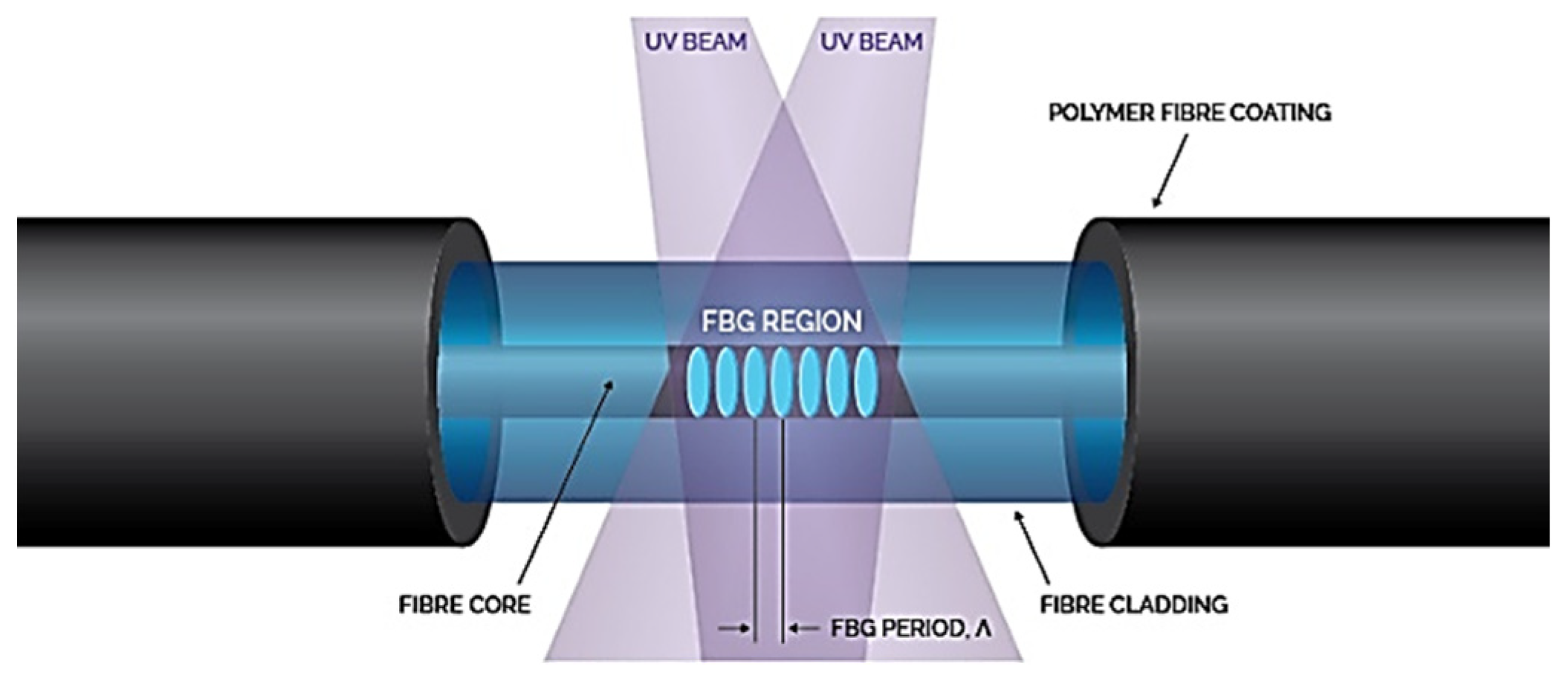
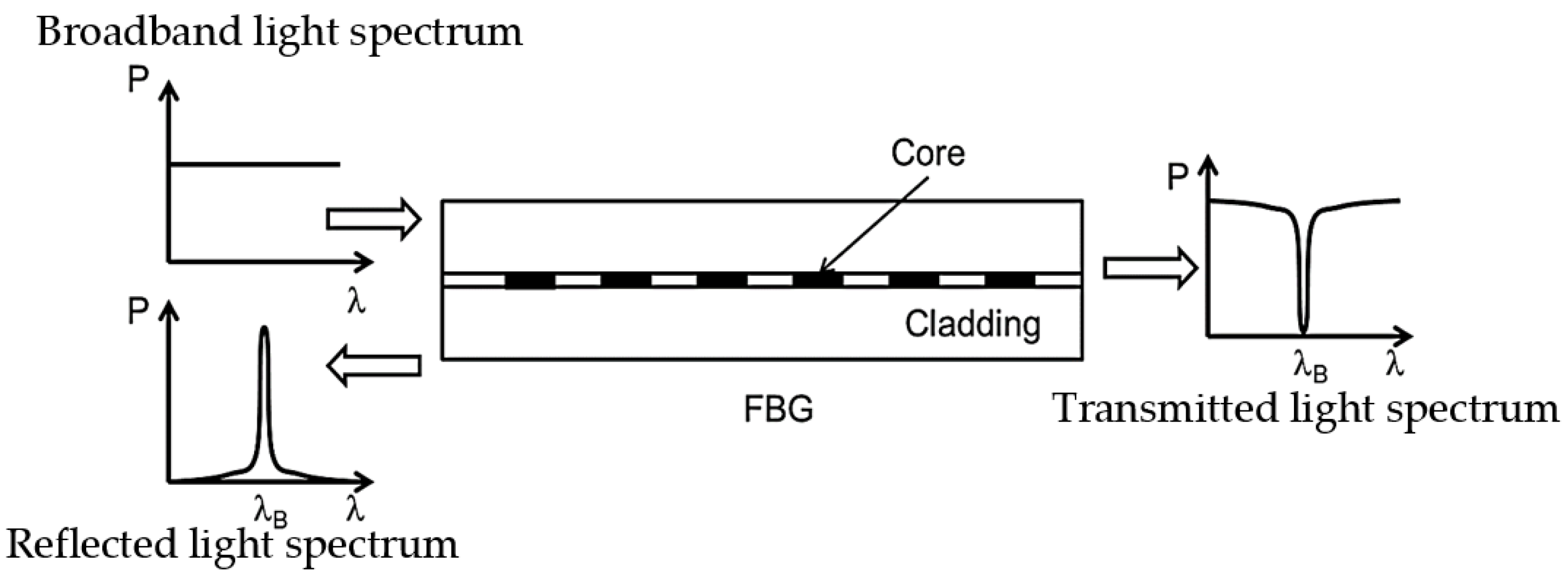
Figure 2.
Operating principles of FBG.
λB = 2 neff Λ


References
- Tavner, P.; Ran, R.; Penman, J.; Sedding, H. Condition Monitoring of Rotating Electrical Machines; The Institution of Engineering and Technology: London, UK, 2008; p. 306.
- Toliyat, H.A.; Nandi, S.; Choi, S.; Meshgin-kelk, H. Electric Machines: Modeling, Condition Monitoring, and Fault Diagnosis; CRC Press: Boca Raton, FL, USA, 2013.
- Hind, D.; Gerada, C.; Galea, M.; Bartolo, J.B.; Fabian, M.; Sun, T.; Grattan, K.T.V. Use of Optical Fibres for Multi-parameter Monitoring in Electrical AC Machines. In Proceedings of the 2017 IEEE 11th International Symposium on Diagnostics for Electrical Machines, Power Electronics and Drives (SDEMPED), Tinos, Greece, 29 August–1 September 2017.
- Fabian, M.; Hind, D.M.; Gerada, C.; Sun, T.; Grattan, K.T.V. Comprehensive Monitoring of Electrical Machine Parameters Using an Integrated Fiber Bragg Grating-Based Sensor System. J. Light. Technol. 2018, 36, 1046–1051.
- Fabian, M.; Hind, D.; Gerada, C.; Sun, T.; Grattan, K.T.V. Multi-Parameter Monitoring of Electrical Machines Using Integrated Fibre Bragg Gratings. In Proceedings of the 2017 25th Optical Fiber Sensors Conference (OFS), Jeju, Republic of Korea, 24–28 April 2017.
- Mellor, P.; Roberts, D.; Turner, D. Lumped Parameter Thermal Model for Electrical Machines of TEFC design. In Proceedings of the IEEE Proceedings B—Electric Power Applications, September 1991.
- Sousa, K.D.M.; Hafner, A.A.; Crespim, M.; Somenzi, J.; De Oliveira, V.; Kalinowski, H.J.; Da Silva, J.C.C. Fiber Bragg Grating Sensing Applications in Temperature Monitoring of Three-Phase Induction Motors. In Proceedings of the 2011 SBMO/IEEE MTT-S International Microwave and Optoelectronics Conference (IMOC 2011), Natal, Brazil, 29 October–1 November 2011.
- Tavner, P.J. Review of Condition Monitoring of Rotating Electrical Machines. IET Electr. Power Appl. 2008, 2, 215–247.
- Sarma, N.; Tuohy, P.; Djurović, S. Condition Monitoring of Rotating Electrical Machines. In Reference Module in Materials Science and Materials Engineering; Elsevier: Amsterdam, The Netherlands, 2022.
- Sousa, K.M.; Bazzo, J.P.; Mezzadri, F.; Bortolotti, F.; Martelli, C.; Silva, J.C.C.; Probst, W.K. Optical Fiber Bragg Grating Sensors Applied on Energy Conversion Systems. In Proceedings of the 2013 SBMO/IEEE MTT-S International Microwave & Optoelectronics Conference (IMOC), Rio de Janeiro, Brazil, 4–7 August 2013.
- Mohammed, A.; Djurovic, S. FBG Thermal Sensing Features for Hot Spot Monitoring in Random Wound Electric Machine Coils. IEEE Sens. J. 2017, 17, 3058–3067.
- Melecio, J.I.; Mohammed, A.; Djurović, S. Characterisation of FBG based Magnetic Field Sensor Response Sensitivity to Excitation Orientation for Rotating Electric Machine Applications. In Proceedings of the 2019 8th Mediterranean Conference on Embedded Computing (Meco), Budva, Montenegro, 10–14 June 2019.
- Suryandi, A.A.; Damian, I.E.; Djurović, S. FBG Magnetostrictive Composite Flux Sensor Response Characterisation for Surface Permanent Magnet Rotor Flux Monitoring. In Proceedings of the 2021 10th Mediterranean Conference on Embedded Computing (MECO), Budva, Montenegro, 7–10 June 2021; pp. 1–6.
- Suryandi, A.A.; Djurovic, S. FBG Magnetostrictive Composite Flux Sensor for Monitoring Rotor Permanent Magnet Flux. In Proceedings of the 2022 11th Mediterranean Conference on Embedded Computing (MECO), 7–10 June 2022; pp. 1–6.
- Mohammed, A.; Melecio, J.I.; Djurovic, S. Electrical Machine Permanent Magnets Health Monitoring and Diagnosis Using an Air-gap Magnetic Sensor. IEEE Sens. J. 2020, 20, 5251–5259.
- Fibres, S. FBG Sensing System. Available online: https://www.smartfibres.com/technology (accessed on 14 October 2022).
- Rao, Y.-J. In-fibre Bragg grating sensors. Meas. Sci. Technol. 1997, 8, 355–375.
- Mohammed, A.; Djurović, S. A study of distributed embedded thermal monitoring in electric coils based on FBG sensor multiplexing. Microprocess. Microsyst. 2018, 62, 102–109.
- Mohammed, A.; Hu, B.; Hu, Z.; Djurović, S.; Ran, L.; Barnes, M.; Mawby, P.A. Distributed Thermal Monitoring of Wind Turbine Power Electronic Modules Using FBG Sensing Technology. IEEE Sens. J. 2020, 20, 9886–9894.
- Werneck, M.M.; Allil, R.C.S.B.; Ribeiro, B.A.; Nazaré, F.V.B. A Guide to Fiber Bragg Grating Sensors: Current Trends in Short- and Long-Period Fiber Gratings; InTech: Rijeka, Croatia, 2013; pp. 1–24.
More