The single-coil eddy current sensors (SCECS) constitute a separate and independent branch among the eddy current sensors. The SCECS sensing element is a single current loop that can be inserted into the measuring zone with harsh and extreme conditions. Such simplicity of the SCECS design ensures sensors’ functioning at high temperatures, reaching 1200 °C and more in gas turbines, high linear speeds of the monitored objects, contamination of the measuring medium by fuel combustion products, vibrations, etc. The main application of the SCECS related to the monitoring the dangerous states of the power plants. The sensors and their cluster compositions make it possible to evaluate a wide range of power plants diagnostic parameters, including radial clearances between the blade tips and the stator of the compressor and turbine of the gas-turbine engine, shaft displacements in the radial thrust bearings, the presence of wear particles of friction pairs in oil system, etc.
- power plants
- blade tips
- radial clearance
- displacement measurement
- bearing assembly
- oil debris monitoring
- single-coil eddy current sensor
- measuring system
- experimental studies
1. Introduction
The high-performance gas turbine engine (GTE) is the basis for creating promising equipment for aviation, land and marine applications. It is known that the main energy, strength, economic and environmental indicators of the GTE are largely determined by the value of the radial clearances (RC) between the blade tips and the stator of the compressor and turbine of the GTE. It is noted by Danilchenko et al. [1] that the dependence of the efficiency value on the RC is nonlinear, and at high-pressure compressor stages, when the RC increases by 1%, the efficiency can decrease by 2%, and the coefficient of aerodynamic stability margin can decrease by 3%. Melcher et al. [2], with reference to [3][4][5], mention the empirical rule according to which a decrease in turbine clearances by 0.25 mm (0.010 in) leads to a decrease in exhaust gas temperature by 10 °C (18 °F) and an increase in turbine efficiency by 1%. As a result, the specific fuel consumption is reduced by 1% and the emission of harmful substances is reduced proportionally. The same source claims that despite the seemingly insignificant effect of reducing the specific fuel consumption, in financial terms, this leads to annual savings of more than $160 million in prices at the time of publication [2]. On the other hand, the excessive reduction of the RC can lead the blades to be cut into the inner surface of the stator shell and cause the emergency engine failure. Therefore, the task of obtaining reliable information about the value of the RC in the flow part of the gas turbine on a running engine is relevant and is the reason for the long-term interest of gas turbine developers in the appropriate measurement tools [1][5][6][7][8][9].
2. Application
Despite the existing variety of methods for measuring the RC [5][8], their implementation is limited by very harsh and even extreme conditions in the gas-air path, which are associated with high temperatures in the measurement zone, reaching 1200 °C or more in GTE turbines, high linear speeds of the monitored blades tips, contamination of the gas-air path by fuel combustion products, vibrations, etc. The measurement methods on the base of eddy current sensors are one of the most promising methods for obtaining information about RC in such extreme conditions [10][11][12][13][14][15][16].
The single-coil eddy current sensors (SCECS) being developed in the Institute for the control of complex systems of the Russian Academy of Sciences [17] constitute a separate and independent branch among the eddy current sensors. The SCECS sensing element (SE) is a single current loop. The plane of the SE contour can be oriented both parallel and orthogonally in the direction of the monitored object.
The descriptions of the original constructions of the SCECS used for measuring of the RC in the GTE are given in works [17][18][19] (Figure 1). The SE of the sensor is a segment of a linear conductor that is connected using current leads and a volume coil of the matching transformer (MT) to the measuring circuit (MC). The SE is inserted into the flow part of the compressor or turbine through the mounting hole in the stator. The MT is placed on the outside of the stator shell in favorable temperature conditions. The interaction of the SE and the blade tip provides measurement information about the RC.
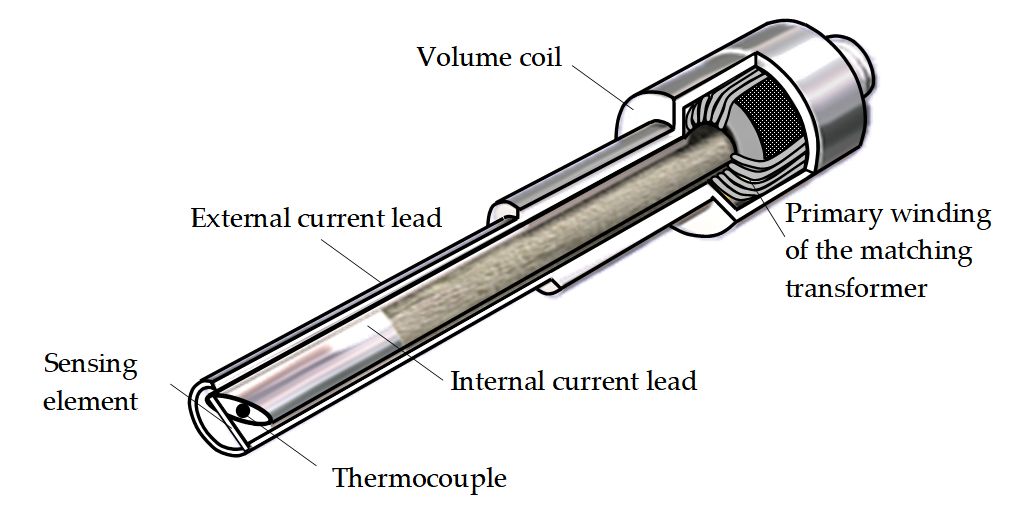
Figure 1. Schematic image of a typical SCECS with SE in the form of a conductor segment.
The computerized measurement systems were built on the basis of the SCECS with a SE in the form of a conductor segment. The systems were used in GTE bench tests to monitor the RC in various operating modes of power plants. The measurement systems provided engine developers with documented data on the value of the RC between GTE movable and fixed structural elements, including information about the RC for each blade of the impeller of the monitored stage of the compressor and turbine of the GTE. The systems performance, metrological consistency and reliability were confirmed during the testing processes. The total operating time of the measurement systems was more than a hundred hours [17][20].
In real conditions the blade tips perform complex multi-coordinate displacements associated with the bending and twisting of the blade body, the axial displacement of the rotor in a radial thrust bearing, etc. The inductance of the primary MT winding of the SCECS contains all information about the coordinates of the blade tips offset and this information can be extracted using the so-called cluster measurement methods [20][21]. The methods involve the concentration of a cluster (group) of SCECS in the measurement zone. The SE of the sensors have a certain orientation relative to each other and the reference system. The number of the sensors is determined by the number of the measured coordinates. The inductances of the primary windings of the MT of the sensors are fixed at the moment when the blades roots pass the selected reference system. The desired coordinates are calculated using the pre-obtained calibration characteristics of each sensor during the processing of the received data. In particular, the axial displacements of the shafts in radial thrust bearings can be estimated in addition to the measured RC. And this, in turn, allows to identify the initial stage of the intensive wear of the friction pair.
The detection of metal wear particles in the lubrication systems of the bearing units of the power plants is another application of the SCECS. Stepanov [22] states that the total number of GTE failures associated with friction nodes can exceed 30%. It is obvious that the timely detection of wear particles in the oil of the GTE lubrication system eliminates the emergency situations associated with the premature bearing failures. The SCECS with orthogonal orientations of the SE contour to the monitored object (a cluster of SCECS) can be used for construction of in-line debris detectors for the GTE oil systems of different diameters. For greater sensitivity the general oil stream on the input of the sensor is split into N independent streams with a smaller cross-section area [23]. Each independent stream is covered by a single current loop located in the pipeline of the engine oil system.The cluster SCECS can determine the size of the metal particle and identify its magnetic properties.
References
- Danilchenko, V.P.; Lukachev, S.V.; Kovylov, Y.L.; Postnikov, A.M.; Fedorchenko, D.G.; Tsybizov, Y.I. Design of Aircraft Gas Turbine Engines; Izd. SamNTs RAN: Samara, Russia, 2008; p. 620.
- Melcher, K.; Kypuros, J. Toward a Fast-Response Active Turbine Tip Clearance Control; NASA Technical Report NASA/TM-2003-212627; NASA: Washington, DC, USA, 2004.
- Shannon Korson; Arthur J. Helmicki; An H/sub ∞/ based controller for a gas turbine clearance control system. Proceedings of International Conference on Control Applications 2002, null, 1154-1159, 10.1109/cca.1995.555924.
- Matthew W. Wiseman; Ten-Huei Guo; An investigation of life extending control techniques for gas turbine engines. Proceedings of the 2001 American Control Conference. (Cat. No.01CH37148) 2001, 5, 3706-3707 vol.5, 10.1109/acc.2001.946211.
- Scott B. Lattime; Bruce M. Steinetz; High-Pressure-Turbine Clearance Control Systems: Current Practices and Future Directions. Journal of Propulsion and Power 2004, 20, 302-311, 10.2514/1.9255.
- Prokopets, A.; Revzin, B.; Rozhkov, A. Necessity for diagnosing radial clearances in the wheel space of gas turbine engines. Gazoturbinnye Tekhnologii 2004, 31, 5–7.
- Kuznetsov, N.D.; Danilchenko, V.P.; Reznik, V.E. Control of Radial Clearances in Turbocompressors of Aviation Gas-Turbine Engines; Samara Aviation Inst.: Samara, Russia, 1991; p. 109
- Inozemtsev, A.A.; Bazhin, S.V.; Snitko, M.A. Optimization of the radial clearances of the turboprop engine of an aviation GTE. Vestn. Dvigatelestr. 2012, 2, 149–154
- Jonathan L. Kratz; Jeffryes W. Chapman; Ten-Huei Guo; A Parametric Study of Actuator Requirements for Active Turbine Tip Clearance Control of a Modern High Bypass Turbofan Engine. Volume 3: Coal, Biomass and Alternative Fuels; Cycle Innovations; Electric Power; Industrial and Cogeneration Applications; Organic Rankine Cycle Power Systems 2017, null, , 10.1115/gt2017-63472.
- Gerasimov, V.G.; Klyuev, V.V.; Shaternikov, V.E. Methods and Devices for Electromagnetic Control; Izd. “Spektr”: Moscow, Russia, 2010; p. 256.
- Flotow, A.; Blade-tip monitoring with through-the-case eddy current sensors. Sensors 2004, 21, 28-35.
- Chana, K.; Lyon, D. Turbo-machinery tip-timing comes of age. Maint. Asset Manag. 2009, 24, 35–40.
- K. S. Chana; V. Sridhar; D. Singh; The Use of Eddy Current Sensors for the Measurement of Rotor Blade Tip Timing: Development of a New Method Based on Integration. Volume 7A: Structures and Dynamics 2016, null, , 10.1115/gt2016-57368.
- V. Sridhar; K. S. Chana; Tip-Clearance Measurements on an Engine High Pressure Turbine Using an Eddy Current Sensor. Volume 3: Coal, Biomass and Alternative Fuels; Cycle Innovations; Electric Power; Industrial and Cogeneration Applications; Organic Rankine Cycle Power Systems 2017, null, , 10.1115/gt2017-63803.
- Ziyu Zhao; Zhenxia Liu; Yaguo Lyu; Xinxin Xu; Verification and Design of High Precision Eddy Current Sensor for Tip Clearance Measurement. Volume 6: Ceramics; Controls, Diagnostics, and Instrumentation; Education; Manufacturing Materials and Metallurgy 2018, null, , 10.1115/gt2018-75643.
- Zhenxia Liu; Ziyu Zhao; Yaguo Lyu; Lingqiang Zhao; Experimental Investigation of Inductive Sensor Characteristic for Blade Tip Clearance Measurement at High Temperature.. Sensors 2019, 19, 3694, 10.3390/s19173694.
- Sekisov, Y.N.; Skobelev, O.P.; Belenki, L.B.; Borovik, S.Y.; Raykov, B.K.; Slepnev, A.V.; Tulupova, V.V. Methods and Tools for Measuring Multidimensional Displacements of Structural Components of Power Plants; Sekisov, Y.N., Skobelev, O.P., Eds.; Izd. SamNTs RAN: Samara, Russia, 2001; p. 188.
- Raykov, B.K.; Sekisov, Y.N.; Skobelev, O.P.; Khritin, A.A. Clearance eddy current sensors with sensitive elements in the form of a segment of a conductor. Devices Control Syst. 1996, 8, 27–30.
- Kuteynikova, M.M.; Raykov, B.K.; Skobelev, O.P. Structural varieties of high-temperature single- coil eddy current sensors. In Proceedings of the XIV International conference “Complex Systems: Control and Modelling Problems”, Samara, Russia, 19–22 June 2012.
- Belenki, L.B.; Borovik, S.Y.; Raykkov, B.K.; Sekisov, Y.N.; Skobelev, O.P.; Tulupova, V.V. Cluster Methods and Tools for Measuring Stator Deformations and Displacement Coordinates of Blade Tips and Blades in Gas Turbine Engines; Skobelev, O.P., Eds.; Izd. Mashinostroenie: Moscow, Russia, 2011; pp. 298.
- Belopukhov, V.N.; Borovik, S.Y.; Kuteynikova, M.M.; Podlypnov, P.E.; Sekisov, Y.N.; Skobelev, O.P. Cluster Methods and Tools for Measuring Radial Clearances in Turbine Flow Section; Skobelev, O.P., Eds.; Izd. Innovatsionnoe Mashinostroenie: Moscow, Russia, 2018; pp. 224.
- Stepanov, V.A. Development and Research of Methods and Tools for Complex Diagnostics of Lubricated Friction Units of Gas Turbine Engines by the Parameters of Wear Products in the Oil. Ph.D. Thesis, Bauman Moscow State Technical University, Moscow, Russia, 2000.
- Borovik, S.Y.; Korshykov, I.G.; Sekisov, Y.N.; Belosludtsev, V.A. Method for Detecting Metal Wear Particles in the Oil Stream of a Running Gas Turbine Engine. RF Patent 2646520, 5 March 2018.