The characteristics of a PV (photovoltaic) module is non-linear and vary with nature. The tracking of maximum power point (MPP) at various atmospheric conditions is essential for the reliable operation of solar-integrated power generation units. Researchers compare the most widely used maximum power point tracking (MPPT) techniques such as the perturb and observe method (P&O), incremental conductance method (INC), fuzzy logic controller method (FLC), neural network (NN) model, and adaptive neuro-fuzzy inference system method (ANFIS) with the modern approach of the hybrid method (neural network + P&O) for PV systems. The hybrid method combines the strength of the neural network and P&O in a single framework. The PV system is composed of a PV panel, converter, MPPT unit, and load modelled using MATLAB/Simulink. These methods differ in their characteristics such as convergence speed, ease of implementation, sensors used, cost, and range of efficiencies. Based on all these, performances are evaluated. In this analysis, the drawbacks of the methods are studied, and wastage of the panel’s available output energy is observed. The hybrid technique concedes a spontaneous recovery during dynamic changes in environmental conditions. The simulation results illustrate the improvements obtained by the hybrid method in comparison to other techniques.
The characteristics of a PV (photovoltaic) module is non-linear and vary with nature. The tracking of maximum power point (MPP) at various atmospheric conditions is essential for the reliable operation of solar-integrated power generation units. This paper compares the most widely used maximum power point tracking (MPPT) techniques such as the perturb and observe method (P&O), incremental conductance method (INC), fuzzy logic controller method (FLC), neural network (NN) model, and adaptive neuro-fuzzy inference system method (ANFIS) with the modern approach of the hybrid method (neural network + P&O) for PV systems. The hybrid method combines the strength of the neural network and P&O in a single framework. The PV system is composed of a PV panel, converter, MPPT unit, and load modelled using MATLAB/Simulink. These methods differ in their characteristics such as convergence speed, ease of implementation, sensors used, cost, and range of efficiencies. Based on all these, performances are evaluated. In this analysis, the drawbacks of the methods are studied, and wastage of the panel’s available output energy is observed. The hybrid technique concedes a spontaneous recovery during dynamic changes in environmental conditions. The simulation results illustrate the improvements obtained by the hybrid method in comparison to other techniques.
1. Introduction
Daily energy demand is rising and normally, to meet those demands, energy is produced by using non-renewable sources such as coal, natural gas, etc.,
[1][2][1,2]. This creates a high amount of carbon emissions. As many countries have decided to pair with zero carbon emission nations, the use of renewable energy sources is increasing day by day
[3][4][3,4]. Due to the free abundance of solar energy, solar panel utilization is increasing rapidly. However, the efficiency of the solar panel is 13–19%
[5]. The reasons for these low efficiencies are rapidly changing atmospheric conditions and the circuits attached to them such as loads, charge controllers, and other devices
[6][7][8][6,7,8].
TheOur main aim is to choose a controller which should be able to track MPP properly, by which
researcherswe can use the solar panel up to its maximum capacity. During its operation, a solar panel sees the load as varying. Therefore, it delivers a lower amount of power during its operation and MPP is lost
[9][10][11][12][9,10,11,12]. For maintaining the MPP operation of the panel, the amount of resistance seen across the PV panel should be fixed such that the solar panel sees a fixed load, i.e., the resistance seen across the panel is fixed (R
o is fixed) and the solar panel produces the maximum amount of power
[13][14][13,14]. The MPPT techniques monitor the output voltage and output current of the solar panels and give a particular operating point to the panel such that the maximum amount of power is delivered.
Many algorithms are developed but traditional methods such as P&O and incremental conductance are widely used because of their simplicity; however, the energy losses are higher with these methods
[15]. Computational power and development of microcontrollers have given rise to methods such as fuzzy logic, particle swarm, neural network, ANFIS, hybrid models, ant bee colony, …, etc.
The various conventional MPPT techniques such as fractional open circuit voltage (FOCV)
[16], fractional short circuit current (FSCC)
[17], curve fitting (CF)
[17], hill climbing (HC)
[18], incremental conductance (INC)
[19], etc. can be observed from the references. The main drawbacks of FOCV and FSCC are less accurate, as they are mostly used for low-power applications
[16][17][16,17]. Popular techniques such as P&O, INC and HC work well, but only produce maximum power during constant insolation conditions, so they are not effective under variable irradiations and shading conditions
[18][19][18,19]. These methods also suffer from poor convergence, more amount of steady-state oscillations, and the slow tracking of MPP
[20].
For better steady-state performance, transient behaviour Intelligent MPPT methods such as neural network, fuzzy logic, and ANFIS are used
[21][22][23][21,22,23]. To overcome difficulties caused by the PI controller, fuzzy controllers have been proposed, as they provide high-performance control, but they lead to a high amount of computational burden and their usage is limited in complex systems
[24].
In the method of P&O with multi-layer ANN, the training of the model and the collection of the datasets is a challenging task
[25], and the ANFIS technique consolidates the power of fuzzy logic and neural networks but the training process requires more numerical calculations for accurate results, which is tough; if the models are not properly trained, the inaccurate response of the hybrid models contain a greater number of oscillations
[26].
A neural network is a fast solution for enhancing efficiency, and it has the ability to deal with uncertainties and can handle the problem without any prior knowledge
[27]. In NN, MPP is tracked in a faster way by modifying the weights of layers according to the learning algorithm. NN controllers show good performance under rapidly varying irradiance and partial shading, in terms of efficiency and responses
[10][28][10,28].
Apart from conventional methods, intelligent methods provide a better performance, and the artificial intelligence overcomes drawbacks caused by methods such as Genetic Algorithms (GA)
[29], Pattern Swarm Optimization (PSO)
[30], fuzzy logic (FL)
[31], Grey Wolf Optimization (GWO)
[32], etc. However, the complexity of design and implementation matters.
The category of hybrid methods reflects the combination of two or more methods of the above-mentioned methods, and the combination increases the effectiveness of the models. Hybrid models such as P&O with multi-layer ANN
[33], ANN with a variable step size of P&O
[34], Genetic Algorithms, P&O with incremental conductance
[34], Gravitational search algorithm with particle swam optimization, and many other algorithms have been proposed but each of them has complexity levels based on their applications. The effective application of algorithm tracking of the maximum power point and the solar panel efficiency can be improved
[35].
Modern algorithms vary in their effectiveness, complexity of circuits, and convergence speed. For good results, traditional methods can be combined with alternative methods to track MPP under varying conditions
[36][37][38][36,37,38]. The ease of implementation of P&O, and the accuracy and rapid recovery of the neural network cannot be ignored, so the combination of these methods helps to reduce uncertainties in the output response.
ReThis
earchers paper compare
s a hybrid control that removes the uncertainties which are seen in P&O, INC, and other algorithms. With the use of the hybrid controller
[39], the performance of solar panels is improved, and the combination present in the model removes the inaccurate responses and it gives a reliable performance in varying atmospheric conditions as well
[40][41][40,41].
2. Modelling of a Photovoltaic Cell
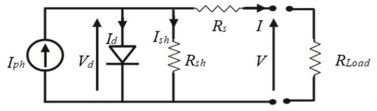
A PV cell consists of a P-N semiconductor junction when it is exposed to light; it generates its equivalent electrical output. PV arrays comprise a series of/parallel combinations of solar cells. The electrical equivalent of a solar cell is shown in
Figure 1. It is represented by a light-generated current source with a shunt diode D, along with parallel and series resistance.
Figure 1. Electrical equivalent of the solar cell.
The Shockley diode equation is used to calculate the characteristic electrical equation of a PV cell. It is written as
where I = solar cell current, I
ph = generated photocurrent, I
sat = reverse saturation diode current, q = charge of electron = 1.60217 × 10
−19 C, k = Boltzmann constant = 1.3807 × 10
−23 J/k, n = diode’s ideality factor, T = cell temperature, R
s = series resistance, R
sh = shunt resistance.
The current I
ph generated is directly proportionate to sun radiation, and the arrangement of series and parallel resistance shows the voltage losses when connected to external contacts and leakage current.
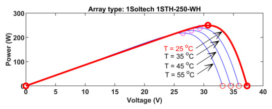
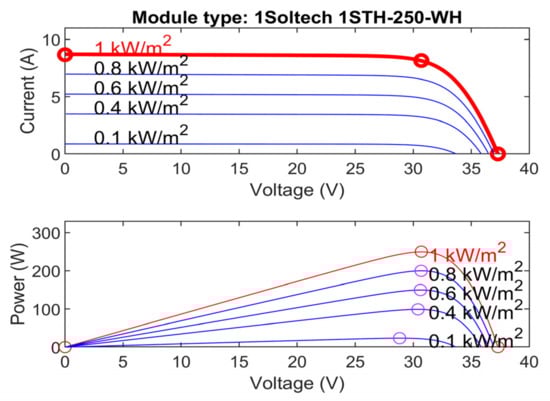
Figure 2 and
Figure 3 depict the module’s p-v curve for different values of irradiation and temperature.
Figure 2. P-V curve for different temperatures at 1000 W/m2 irradiation.
Figure 3. I-V, P-V curves for various irradiations at 25 °C.
The simulation model of the PV block has been used for obtaining the curves, and for more power, cells are connected in a series of/ parallel combinations to build a PV array.
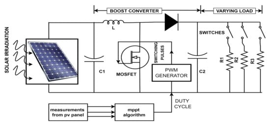
The output characteristics of the panel are nonlinear and depend on temperature and irradiation. To obtain maximum power from the panel, the resistance seen by the panel should be maintained constant. For this purpose, a power converter such as a DC-DC boost converter is utilized for load matching to the PV panel, to obtain the maximum power out of the panel.
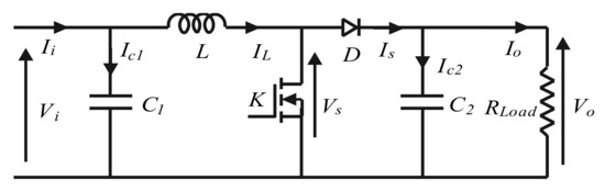
3. DC-DC Boost Converter
A boost converter serves as a switch mode regulator, converting an unregulated dc output voltage to a controlled dc output voltage. A boost converter (
Figure 4) comprises a switch K (transistor/MOSFET), diode, filter capacitor, an inductor, as well as a resistor.
Figure 4. Schematic of the DC-DC boost converter.
The control operation is performed by controlling the switch’s duty ratio, and in continuous mode, when the switch is ON, the diode is in an OFF state and energy is stored in the inductor. When the switch is OFF, the stored energy is dissipated in the resistor, through the diode path.
The output voltage of the converter is given as
where
d = duty cycle.
4. MPPT Control
In a PV module, there is one single operating point at a given point of time where maximum power can be drawn. The operation mainly depends on the load characteristics to which it is connected. If a panel is directly connected to a load, the operating point of the panel is not optimal. Therefore, an MPPT controller should be connected between them.
The MPPT controller adjusts the resistance seen by the panel R
T, such that it sees a constant load, so as the output changes, the control input to the converter changes such that the input impedance of the controller is maintained as constant.
In such a case, R
T seen from PV will remain constant, irrespective of load resistance. From this, the operating point will be maintained constant and the maximum power will be drawn from the panel. The MPPT control scheme for the solar panel is shown in
Figure 5, and the specifications can be found in
Table 1.
Figure 5. MPPT control for the PV system.
Table 1. Parameters and specifications of PV module.
).
Table 2. Table showing the variation of parameters.
4.1. MPPT Algorithms
Many techniques have been developed for implementing MPPT. The techniques differ in implementation, cost, speed, and efficiency. The most widely used are perturb & observe method (P&O), incremental conductance (INC), and fuzzy logic control method.
4.2. Perturb and Observe Method
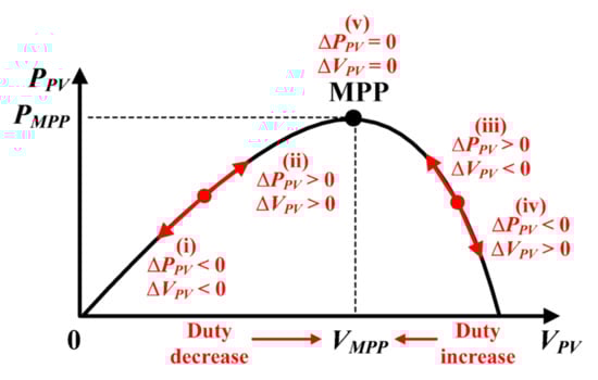
Owing to its simple design and ease of operation and execution, the perturbation and observation technique is the most widely used technique. The concept behind the P&O method is to modify the operating voltage of the solar cell until the maximum power is obtained from it. The impact on the system is observed by modifying the system voltage.
If the operating point lies in regions 1, and 2 in
Figure 6 [11], the perturbation is adjusted such that the point reaches the MPP. If the operating voltage is perturbed and if the power is increased (dp/dv > 0), then
researchwe
rs can see that point is now moving towards the MPP, whereas if it decreases (dp/dv < 0), then the direction of perturbation is reversed. The process will continue until the MPP is reached at every point in time. Based on the previous duty ratio, the next duty ratio is calculated by checking the differences between the power and voltage values.
Figure 6. dp/dv sign at various points of the curve
[11].
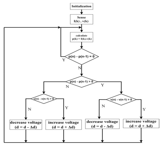
The flow chart of the P&O algorithm is shown in
Figure 7.
Figure 7. Flowchart for P&O algorithm.
The P&O algorithm could not track the MPP under rapidly varying atmospheric changes. The system has been tested for various levels of irradiation, load, and temperatures (shown in
Table 2
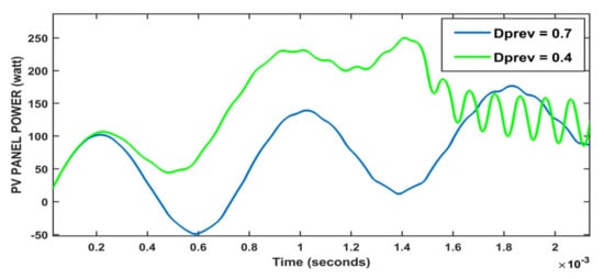
The performance of the system for various levels of perturbation size is seen in
Figure 8. It indicates that with an increasing/decreasing Dprev value, the rise time taken to obtain the MPP does not become affected, but by increasing the Dprev value, the smoothness of the curve increases.
Figure 8. The effect of perturbation step size on the behaviour of the P&O method.
The performance of the system for constant and varying atmospheric conditions is shown in
Figure 9,
Figure 10,
Figure 11 and
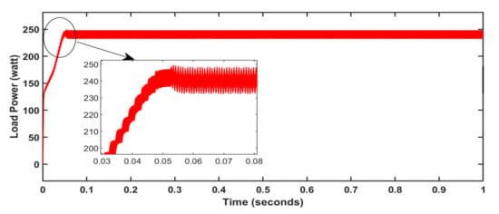
Figure 12. The output reaches a maximum at 0.05 s (
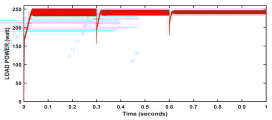
Figure 9), and then the output is maintained constant at 247 W. At variable irradiation and variable loads in
Figure 10,
rwe
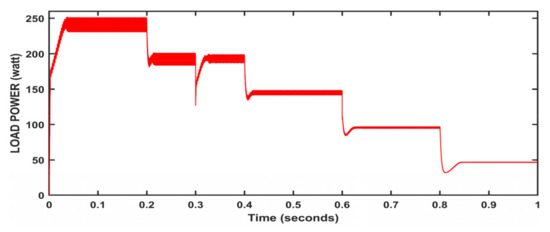
searchers can observe that the output waveform takes time to get back to the steady state after disturbances and output power changes with respect to the input. Only under varying loads, the output is nearly constant except at load disturbances (
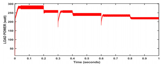
Figure 11). At variable temperatures and variable loads, the output wave took time to reach the steady point. However, after load disturbance, it reached the steady point quickly under input variations (
Figure 12).
Figure 9. Algorithm performance at constant atmospheric conditions; T = 25 °C, w = 1000 W/m2, R = 10 Ω.
Figure 10. Algorithm performance at variable irradiations and variable loads; T = 25 °C.
Figure 11. Algorithm performance at variable loads; T = 25 °C, w = 1000 W/m2.
Figure 12. Algorithm performance at variable temperatures and variable loads; w = 1000 W/m2.