Your browser does not fully support modern features. Please upgrade for a smoother experience.
Please note this is a comparison between Version 1 by Stephane Abanades and Version 2 by Sirius Huang.
New sustainable and alternative energy carriers are required to limit the CO2 emissions and climate change arising from intensive fossil fuel utilization and combustion. The solar thermochemical production of synthetic fuels without greenhouse gas emission can be achieved via the splitting of H2O and CO2, using concentrated solar energy as an external high-temperature heat source for the chemical process. Two main solar reactor concepts can be proposed to implement redox cycles.
- solar fuels
- water-splitting
- CO2 conversion
- thermochemical cycles
- redox-active materials
- solar reactors
- hydrogen and syngas production
- metal oxides
1. Introduction
Two main solar reactor concepts can be proposed to implement redox cycles: the reactors in which both cycle steps can proceed in a single reactor chamber and the reactors in which the functions of reduction and re-oxidation are decoupled in different systems allocated to each step. Concentrated solar heat integration is of prime importance for achieving an optimal solar reactor efficiency [1][2][188,189]. The most relevant solar reactor technologies developed to date and applied specifically to two-step cycles are presented.
2. Single-Chamber Solar Reactors
This kind of solar reactor gathers the different available technologies for implementing the non-volatile oxide cycles. The reacting material can be either in the form of divided particles (grains or powders of pure material or coated as thin films) or structured with a porous architecture (via the coating of a substrate or by shaping) [3][190]. In both cases, the target is to offer a large specific surface area for reactions to promote transport phenomena at the solid–gas interfaces.
The possible reactor technological concepts include the fluidized beds with internal particles’ circulation, namely circulating fluidized beds (Figure 1). Due to the particles’ motion and mixing, a homogenized temperature of the solid can be obtained, the reduction/re-oxidation steps can be performed in alternance, and the particles’ sintering can be alleviated. The gas flow is injected in the central part of the cylindrical reactor for the particles’ fluidization and for transporting them in the upper region of the bed, so that the upper part of the particle bed is located at the focal point of the solar concentrating system, enabling the reduction reaction. The gas flow-rate is dependent on the particles’ size and density that determine the conditions needed for their proper fluidization. When reaching the solar-irradiated zone, the particles return down at the bottom part of the bed via the annular zone at the periphery of the draft tube, thereby transferring a part of the absorbed energy from the top irradiated zone to the bottom zone. An effective thermal homogenization on the vertical axis can be achieved, thus ensuring a more uniform temperature in comparison with packed-beds, and the inert gas flow-rate required for particles’ fluidization is restricted to the central region. Once the thermal reduction step is finished, solar irradiation is then stopped, and a fraction of the inlet flow of inert gas is replaced by the oxidizing gas. This reactor concept was, for instance, implemented and operated by using ZrO2 supporting particles coated with Ni-ferrite (NiFe2O4) [4][191].
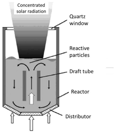
Figure 1.
Scheme of a solar-driven fluidized-bed reactor with internal particles circulation.
Another interesting reactor concept consisting of a monolithic reactor was developed, devoted to the solar-driven production of hydrogen fuel, in the framework of a 100 kW (thermal) pilot prototype (Figure 2) [5][96]. The reacting oxide material (e.g., doped ferrite) is coated on a porous ceramic structure such as honeycomb monolithic, and the whole system acts as both a volumetric radiative absorber and a thermochemical reactor. To allow continuous fuel production during solar operation, two similar parallel reactors are settled in the focal area. While the first one is subjected to concentrated solar radiation for the thermal reduction step, the second one operates the material re-oxidation (ferrite hydrolysis), and vice versa for cycle steps’ alternance. Such reactors thus involve a fixed reactant, and the temperature alternance between each step ensures continuous operation via the heliostats’ monitoring for control of incident flux.
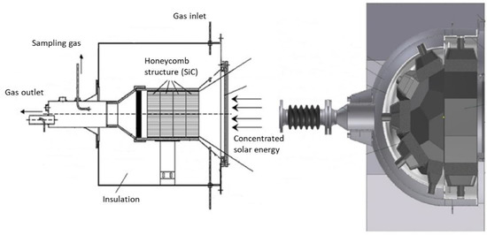
Figure 2.
Schemes of monolithic solar reactors integrating a porous structure.
Other types of monolithic solar reactors enabling the integration of massive porous structures made of ceria (monoliths, reticulated foams) have been recently developed (SUNFUEL solar reactor installed at CNRS-PROMES in Figure 3) [6][7][8][130,131,136]. In such reactors, the reactive material is usually cycled at two distinct temperatures for optimized process performance (temperature-swing cycles), although isothermal cycles have also been considered but with much lower fuel production output [9][10][11][12][13][14][15][16][114,192,193,194,195,196,197,198]. Reticulated porous ceria structures (foams) were prepared by hard templating with a suitable geometry and different pore size densities and then cycled under a wide range of operating conditions (temperatures, O2 partial pressure, gas flow rates, oxidant mole fraction, H2O or CO2 oxidant) in order to determine the material’s redox activity. Such foams showed remarkable performances for the splitting of H2O and CO2 (fuel production rates up to ~10 mL/min/g) thanks to their dual scale porosity (open cell structure for homogeneous heating and interconnected porosity inside the struts for enhancing the reactivity with the gaseous oxidant species). The cycling stability of materials was assessed during a high number of successive cycles in the reactor under real concentrated solar irradiation conditions [6][7][17][130,131,199]. Ceria foams coated with a thin perovskite layer (La0.5Sr0.5Mn0.9Mg0.1O3) were also elaborated, which allowed an improvement of the global fuel output at the expense of slower oxidation kinetics due to a diffusion barrier at the surface [8][136]. Moreover, ordered porous structures with a graded porosity (to favor volumetric solar radiation absorption) were designed and manufactured by 3D printing, and their cycling was studied in the solar reactor, which also proved to be effective for the splitting of H2O and CO2 [18][139]. Another shaping strategy was considered consisting of the robocasting of 3D printed and sintered ceria scaffold structures with hierarchical porosity for solar thermochemical fuel production from the splitting of CO2 [19][200].
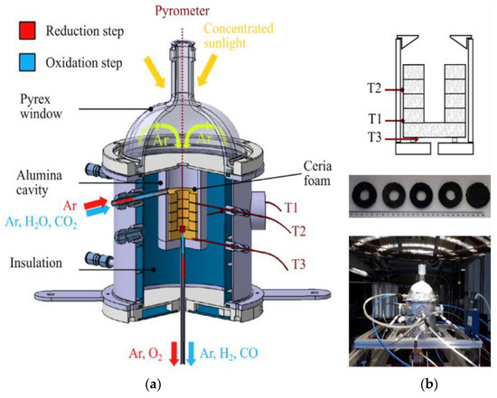
Figure 3. Solar redox cycling of ceria reticulated foams: (a) Scheme of the SUNFUEL solar reactor integrating reactive ceria foams for two-step H2O and CO2 splitting; (b) Foam structure composed of a stack of disc and rings, and pictures after successive cycles performed with a CeO2 foam under solar heating.
Other alternative shaping strategies were considered in order to integrate the materials in the reactor in a divided form (e.g., particulates). For example, 3-dimensional ordered macroporous (3DOM) ceria materials were synthesized via biomimetics (with cellular ordered microstructure prepared from a cork template, cell diameter ~25 µm). The materials were cycled in different solar reactors with direct or indirect heating [20][21][22][132,133,134]. Ceria porous microspheres were also elaborated from ion exchange resins and cycled in solar reactors [23][137], as well as fibrous sintered ceria pellets to demonstrate their suitability for solar fuel production application [24][140]. The obtained performances were similar to those of ceria foams (~200–300 µmol/g of H2/CO, peak production rate: 9.5 mL/min/g) under comparable cycling conditions.
Alternatively, a membrane solar reactor was developed for continuous and isothermal splitting of CO2 (and H2O) under a gradient of O2 partial pressure across the membrane [25][26][27][28][29][138,201,202,203,204]. As described in Figure 4, the original process was demonstrated in a solar reactor under high-flux solar irradiation using a dense ceramic membrane with tubular shape (mixed ionic-electronic conducting materials, MIEC) that separates a reduction zone at low pO2 (sweep side) and an oxidation zone fed with reactive gas flow (feed side). The reactive part of the tubular redox membrane was located inside a well-insulated cavity receiver for homogeneous heating, which was fed with a carrier Ar flow on the sweep side to facilitate the transport and removal of the permeated oxygen [25][138]. The dynamic response of the solar fuel evolution upon varying the operating conditions in the membrane reactor (temperature, CO2 mole fraction, and feed gas flow rate) was assessed by measuring the evolved gas production rates. Continuous CO2 dissociation was achieved on the feed side inside the tubular membrane with in situ spatial separation of O2 and CO across the membrane. The CO and O2 production rates were sharply enhanced by increasing the operating temperature (up to 1550 °C). The increase in CO2 concentration or oxidant gas flow rate also enhanced the process performance. Reliable solar membrane reactor operation, under real concentrated sunlight, was successfully demonstrated for the first time, with stable and unprecedented CO production rates up to 0.071 μmol/cm2/s at 1550 °C and CO/O2 ratio of 2. An original composite membrane integrating two different perovskite coatings on each side of the ceria membrane, with a sandwich-like structure, was designed and tested under concentrated sunlight [26][201]. Thin perovskite layers (inner side: La0.5Sr0.5Mn0.9Mg0.1O3 and outer side: Ca0.5Sr0.5MnO3) were coated to enhance oxygen ion transfer. With such a membrane structure, a CO production increase (>0.13 μmol s−1 cm−2) and simultaneous oxygen separation (with CO:O2 ratio of 2) were observed, respectively, on the inner and outer sides of the oxygen transport membrane. These results outperform the production rates achieved with uncoated ceria membranes, which demonstrates the interest of using composite membranes made of a densified core material coated with redox-active perovskite layers.
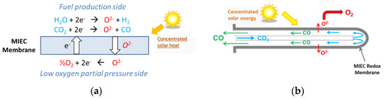
Figure 4. Membrane solar reactor: (a) Operating principles of the isothermal MIEC membrane with mixed oxygen-electron transfer under a gradient of pO2 between both membrane sides; (b) Gas flow on the sweep and feed sides, and ion transport through the tubular dense membrane (closed one-end) for continuous separation of oxygen and CO.
3. Decoupled Reactors for Separated Reduction and Oxidation Steps
This type of reactor concept is adapted to the cycles in which the reduction step is carried out in a first solar receiver/reactor, and the oxidation step for H2/CO production is performed separately at a lower temperature in a second oxidation reactor. The heating and cooling stages of the cavity receiver are thus not required, and the solar reactor is specifically designed and optimized for the reduction step. The global system comprising both reactors (solar and oxidation reactors) can potentially be operated in a continuous mode [30][205]. The most widespread concept relates to the solar reactors devoted to the thermal reduction of volatile oxides.
A prototype reactor with rotating cavity (rotary kiln type) was developed for ZnO dissociation (Figure 5) [31][206]. Thanks to the cylindrical cavity rotation, the ZnO particles, that are injected by the means of a screw feeding system in the axial region, are evenly distributed and spread on the reactor walls, thus avoiding the existence of hot regions ascribed to the non-uniform incident solar flux. A permanent inert gas flow is required, and its injection at the rear face of the quartz window allows its protection from Zn vapor deposition. The produced gas species are exiting via the outlet annular section along the screw feeding system, where their cooling/quenching is ensured by the injection of large amounts of inert gas at room temperature (such a quenching method thus consumes inert gas, inducing energy penalties for inert gas separation and recycling). The Zn particles (with ~50% Zn content purity) are finally separated and recovered by filters at the outlet. A different prototype of a rotating solar reactor was also developed at CNRS-PROMES for continuous operation with direct ZnO particles’ injection in the high-temperature cavity and Zn product recovery as a fine reactive powder (composed of nanosized particles) at the reactor outlet (Figure 6) [32][33][207,208].
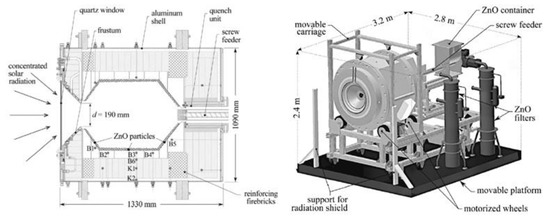
Figure 5.
Scheme of 100 kW (thermal) prototype solar reactor for ZnO thermal dissociation.
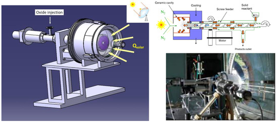
Figure 6.
Continuously particle-fed solar reactor for ZnO reduction and Zn production.
The solar reactor prototype with the highest thermal power was developed during the European project Solzinc for the reduction of zinc oxide with carbon materials (Figure 7) [34][67]. This reactor is thus designed for the carbothermal-reduction of ZnO at lower temperatures (below 1000 °C), which noticeably alleviates the thermal constraints imposed on the reactor materials and the technological issues associated with the gas quenching required in the thermal dissociation process, at the expense of the carbon source requirement. The solar carbothermal reduction of ZnO was mainly studied in shrinking packed-bed reactors, thus based on a similar technology, at smaller scale [35][77].
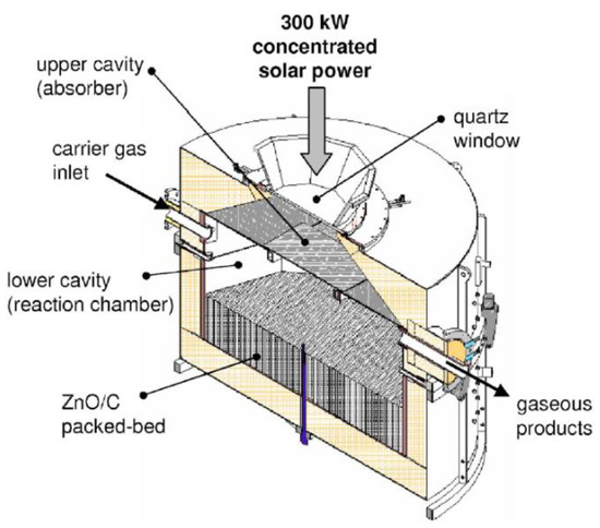
Figure 7.
Scheme of the 300 kW (thermal) solar reactor designed for the carbothermal reduction of ZnO.
The considered solar reactor is composed of two separated cavities. The upper cavity of the reactor, composed of SiC plates, acts as the solar receiver, as it receives and absorbs solar irradiation in order to re-emit the energy to the lower cavity that contains a packed-bed of ZnO particles, which are heated by radiations emitted by the separation heat transfer plate. This configuration enables a production of a significant amount of reduced Zn particles without the risk of particles’ deposition on the quartz window. The production of 50 kg/h of Zn with 95% purity was achieved, at an operating temperature range of 1300–1500 K, with a process efficiency of 30%.
A different vertical-axis solar reactor concept was developed for the thermal ZnO dissociation (named Gravity Fed Solar Thermochemical Reactor, Figure 8) [36][209]. In this concept, particles are injected via fifteen distributors located at the periphery of the reactor to homogenize the particles’ distribution in the reactor cavity. Driven by gravity, the fed particles fall as a curtain on the surrounding plates made of a refractory material forming the cavity receiver, and the cavity slope and surface were designed for proper operation. The particles are reduced and vaporized zinc is produced during their progress downward in the conical region, while the evolved gases are carried by an inert gas flow to the reactor outlet at the conical cavity bottom. The unreacted particles are then recovered in the annular region located between the gas outlet and the lower part of the reactor.
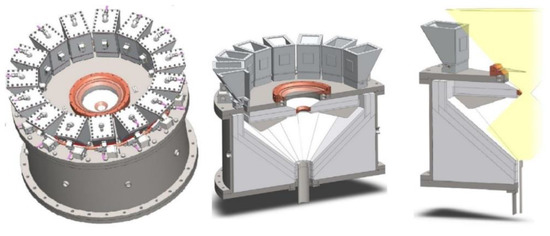
Figure 8.
Scheme of the solar reactor with gravity-driven particles injection.
The PROMES laboratory also designed and developed new technological concepts suitable for the continuous thermal reduction of volatile oxides. A first prototype featuring a rotating cavity was assembled, as already shown in Figure 6 [33][208]. One of the goals and originality of the designed system was the possibility to conduct reactions under reduced pressure to enhance the kinetics [37][38][50,51]. A second different reactor prototype with a vertical solar irradiation axis was then developed, also enabling operation at reduced pressure (Figure 9) [39][84]. The reacting material, in the form of compressed pellets, is continuously fed into the insulated cavity via a screw feeding piston in the lower cavity part, and it is simultaneously heated by both the direct concentrated solar radiation and the emitted IR radiation from the cavity walls. Another advantage of this kind of reactor is a low distance between the reduction zone in the cavity and the outlet evacuation zone connected to the particle filtration system, which alleviates the recombination reaction. The metallic fine powders (Zn or SnO) recovered in the filter at the outlet contain ~40% of reduced species for ZnO and ~70% for SnO2, under an operating total pressure of about 20 kPa with a solar-to-chemical energy conversion efficiency of about 2–3%.
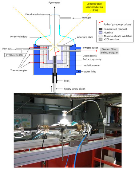
Figure 9. Solar reactor prototype designed and tested for the thermal dissociation of volatile oxides (ZnO, SnO2) with continuous reactant injection in the form of compressed pellets.
With the objective to integrate heat between both cycle steps and to warrant continuous operation, two different reactors with moving solid oxide reactant were developed, enabling an integrated flow and transport of the reacting solid from one reaction chamber to the other. The “CR5” concept (named Counter-Rotating-Ring Receiver/Reactor/Recuperator, Figure 10a) involves two chambers separated by a stack of rotating rings [40][210]. The rotation drives the ring surface coated with metal oxide (ferrites) from the reduction zone to the oxidation zone. The hot part that exits the reduction zone of one reheats the entering colder parts of its two neighbors, thus enabling heat recovery (30%). The challenge and limitation of this concept reside in this assembly of rings, which must also ensure an efficient gas-tight separation of the two chambers’ atmosphere. Though the concept was experimentally tested with a prototype involving cobalt ferrites, the available data are not sufficient to really assess its actual efficiency.
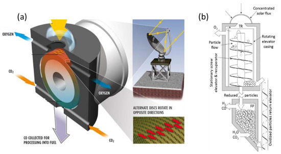
Figure 10. Scheme of integrated reactors with solid oxide displacement between redox steps: (a) Diagram of CR5 reactor; (b) Prototype of circulating dense bed reactor.
In the other concept (Figure 10b) [41][211], the particles are driven by a stationary screw towards the upper part of the reactor where they are subjected to concentrated radiation. Due to gravity, they go back down through the hollow axis of the screw, which acts as a heat exchanger between upward and downward particles, to the re-oxidation chamber. The authors highlight the possibility for it to continuously operate, unlike the fluidized bed, which allows a batch operation. This concept was, however, not proven, and achieving tightness due to stacked particles seems difficult, similar to the transportation of particles to the high temperature zone.