Your browser does not fully support modern features. Please upgrade for a smoother experience.
Please note this is a comparison between Version 1 by Cesar Alejandro Carrasco Payero and Version 3 by Beatrix Zheng.
3D virtual management is a topic of growing interest. The AEC industry is undergoing a real revolution because of the technological changes that are taking place. Synchronized 3D visualization is one of the tools being deployed at an accelerated pace. This, together with collaborative work, contributes to optimal management for all stakeholders. The integration of geographic information systems and building information modeling and heritage building information modeling (BIM) is one of the most innovative concepts; it enables the generation of collaborative, fluid systems.
- building information modeling
- BIM
- heritage building information modeling
- HBIM
1. Technical Progress
The technical progress regarding the integration of geographic information systems (GIS) and building information modeling (BIM) and BIM and HBIM models is based on 3D representation and interoperability. In what follows, aspects related to file formats, 3D model geometry and its semantics, data, and the internet of things are developed.
1.1. File Format
In GIS and in BIM and HBIM environments there are many formats for storing 3D geometry. Among others, the formats proposed by European Directive 2007/2/CE for the Infrastructure for Spatial Information in Europe (INSPIRE) are available [1][2][4,24], namely gbXML, Open Geospatial Consortium (OGC) [3][4][36,37], LandInfra, and IFC. Among these, the most recognized and widely used open standard in GIS is the one issued by the OGC, the “City Geography Markup Language (CityGML)”; in BIM, they are IFC formats [5][1].
The CityGML format is an open, standardized geometry model based on XML [1][4][6][4,37,38]. This format is still suitable for GIS and BIM integration because of its data interchangeability [7][39]. It is the most widely used international standard for storing and exchanging three-dimensional city models with semantics [8][9][10][11][23,40,41,42] in the geospatial domain [2][24]. The CityGML core module defines the basic concepts and components of the data model; therefore, it is unique and must be implemented by any system.
The IFC standard has been developed by building smart [1][4] as an open international standard for BIM [9][40]. It is a standard and interoperable format that is object oriented and capable of representing objects semantically [12][10]. It serves as an exchange format between different platforms, allowing BIM models to preserve all the details that are integrated in that model [5][10][1,41].
There are still many problems and technical barriers related to integration; the fundamental one is the recognition of the nature that characterizes a project when thwe researchers try to link a BIM model (IFC) and a GIS model (cityGML), causing loss of information. The reality is that an IFC file, by itself, does not contain all the information of the model from which it was extracted, and, additionally, there is a difference in the nature of the BIM and GIS models; that is, a BIM model is structured with geometric figures whose representation depends directly on parameters (width, length, thickness, texture, etc.)—a quite light model; on the other hand, the GIS model is made up of meshes (junctions of points/triangulations) that, although quite flexible, have the disadvantage that a triangulation represents more than one element of the model, which makes the individualized treatment of the characteristics of an element impossible. Additionally, the file is weighty because of the amount of information that needs to be managed to generate the mesh. It is therefore necessary to continue working on an intermediate mechanism between the two types of models to achieve an integration that enables both models to interact under a nature common to both.
1.2. Geometry of the 3D Model and Its Semantics
In the GIS and BIM and HBIM integration, the geometry of the model is directly defined with its semantics. The semantics refers to the levels with which the 3D model is represented in the different preforms. These levels are parameters to measure the degree of semantics of the objects. They are divided into LOD (levels of detail)—more often referred to as “LoD” with lowercase “o”—for a GIS system, LOD (levels of development) for a BIM element, and LOK (levels of knowledge) in HBIM. The latter arise from the fact that authors wish to define levels of detail applicable to the management and conservation of built heritage [13][16].
The LoDs (from GIS) are developed in five levels of detail, from LoD0 to LoD4 (Figure 19), having different precisions and minimum dimensions, which are used to represent objects in the model of a three-dimensional city (El-Mekawy et al., 2012; Fan et al., 2011). Thus, LoD0 represents a terrain region in 2.5D; LoD1 are simple volumetric model representations, that is, “boxes”; LoD2 add the roof structure (flat or sloping) to the previous one; LoD3 present the architectural details on the exterior of the model, such as openings and wall textures; and, finally, LoD4 includes the representation of details of the interior of the model, such as the partitions and the delimitation of different spaces [10][41]. LoD3 and LoD4 levels containing architectural details such as balconies, windows, and rooms rarely exist because, unlike LODs (from BIM), their modeling requires multiple datasets that must be acquired with different technologies, and, often, this requires a lot of manual work [11][42]; hence, today, most buildings on an urban scale are represented, at best, in LoD3 [14][43].
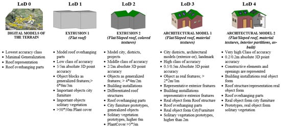
Figure 19.
Qualities of levels of detail LoD/LOD CityGML (adapted from Consortium, 1994).
Inappropriately, BIM LODs are often interpreted as being associated with a level of detail rather than a level of development. As a project goes through different phases, its semantics increase at different levels of development [9][40] classified into five groups, from LOD100 to LOD500 [13][16] Popovic et al., 2017) (Figure 210). LOD100, LOD200, and LOD300 refer, respectively, to the conceptual, schematic, and detailed designs, while the LOD400 and LOD500 refer to a level of development associated with the complex documentation of the project, reaching the final character of an as-built [9][40].
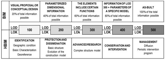
Figure 210.
Knowledge levels (LOK)—HBIM and levels of development (LOD)—BIM.
LOK knowledge levels represent the semantics of heritage management [13][16], classifying from LOK100 to LOK500 (Figure 8). LOK100 is associated with the identification of the heritage asset and its basic characterization; LOK200 enables the graphic characterization and sufficient information for the development of actions related to the legal protection of the asset and its strategic planning; LOK300 provides greater detail about the characterization of graphic entities to the point of being able to show the results of specialized investigations carried out using archaeological methodology or other specific disciplinary follow-up and diagnosis studies; LOK400 includes specific conservation and intervention actions on the asset’s elements; and finally LOK500 deals with efficient management of HBIM models.
1.3. Data Generated by Surveying Activities
The collaboration between various stakeholders involved in a project consists of sharing data through interaction, communication, exchange, and coordination [15][9]. Feeding a model with existing data enables not only better visualization but also coordination between views and efficient construction management with considerable cost reduction, whether in the construction, rehabilitation, operation, or maintenance phase.
Today, the most widespread dimensions of a BIM model range from 3D to 7D. 3D represents the three-dimensional model of the project, 4D includes the information about its time sequence [16][44], 5D refers to the costs of the model elements, 6D contains information on sustainability, and, finally, 7D includes aspects of the management programs in the operation and maintenance phase [13][16].
As for the HBIM models, and with the objective of coordinating all existing information, another five dimensions are usually adopted, coinciding in name with those referred to for BIM models, 3D–7D, but with somewhat different concepts. Thus, the 3D HBIM model, in addition to being related to the three-dimensional model, considers the data collection performed on the building. 4D is related to historical evolution. 5D cannot be directly related to the actual construction costs as in BIM, since, obviously, the building is already constructed; therefore, the transfer of this dimension from BIM to HBIM is not direct, and a parallelism is usually established with the estimated cost of the associated intervention process [13][16]. 6D includes the cultural context, and, finally, 7D addresses preventive programs and conservation of the building. Figure 311 illustrates the relationship between the BIM and HBIM dimensions.
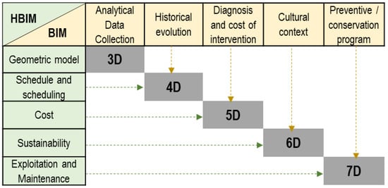
Figure 311.
Dimensions BIM vs. HBIM.
1.4. Applicability of the Model under the Concept of Smart City
Smart city has been a well-adopted concept in urban development worldwide [17][18][19][45,46,47], being, by analogy, the “motherboard” where smart buildings should be inserted, generating a new public–private relationship [7][39]. It encompasses different definitions, but all of them share, as a basic pillar, the use of technology [20][27], constituting a facilitating element in the improvement of public services, sustainability, and efficiency [15][9]. Smart city 3D [4][21][37,48], part of the digital twin concept, which was introduced in 2003 within a manufacturing concept and life-cycle management [16][22][44,49]. Digital twins integrate IoT, machine learning, artificial intelligence, and big data analysis to create digital simulation and feedback models, which interact with their physical counterparts, updating themselves [23][50]. Figure 412 lists several application cases and technologies developed in the field of digital twins of cities, extracted from the bibliographic consultation carried out.
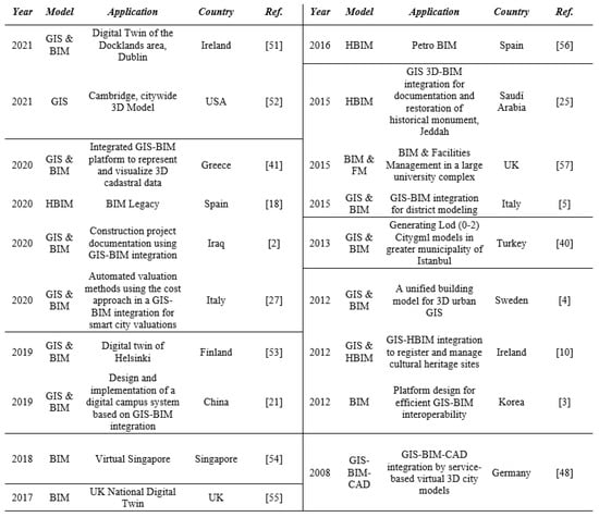
Figure 412. Some examples and application cases of digital twins extracted from the bibliography [1][9][10][12][20][21][24][25][26][27][28][29][30][31][32][33][34][35][36].
Some examples and application cases of digital twins extracted from the bibliography [2,3,4,5,10,18,21,25,27,40,41,48,51,52,53,54,55,56,57].
2. SWOT Analysis
In summary, a digital model can be given a number of applications that correspond to the model of reality. To identify the main aspects that could affect the application of GIS and BIM and HBIM integration in the above possible uses organized according to their relationships with the key-concepts of application of the model of the co-occurrence analysis qualitative results (heritage conservation, cost and quality control, construction project, life-cycle analysis, facilities management, sustainability and energy efficiency, interoperability and semantics, and urban and transport planning) a SWOT analysis is proposed (Figure 513). The result of this SWOT analysis is shown in Table 15.
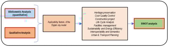
Figure 513.
Data source for SWOT analysis.
Table 15.
SWOT analysis of GIS and BIM and HBIM integration.
| Strenghts | |||||||||||||||
|---|---|---|---|---|---|---|---|---|---|---|---|---|---|---|---|
| Heritage Conservation | Cost and Quality Control | Construction Project |
Life Cycle Analysis | ||||||||||||
| Manage semantic knowledge information | Reduce costs [14] | Reduce costs [43] | Synchronize design and planning [37] | Synchronize design and planning [29] | Evaluate model changes over time [38] | Evaluate model changes over time [13] | |||||||||
| Be able to contain geometric or semantic information [9][39] | Be able to contain geometric or semantic information [26,40] | Improving product quality and optimizing management [30] | Improving product quality and optimizing management [51] | Simulate the environment surrounding the project and its reactions [36] | Simulate the environment surrounding the project and its reactions [57] | Plan the maintenance and renewal of assets | |||||||||
| Modeling quantitative and qualitative information [37] | Modeling quantitative and qualitative information [29] | Managing risk and safety [40] | 58 | [41][42][ | ,59 | 43 | ,60 | ] | ,61 | [44] | ,62 | [45] | Managing risk and safety [,63] | Manage all project information | Simplify and reduce the time to obtain and update information |
| Integrate and digitally manage heritage | Improve productivity [46][47] | Improve productivity [64,65] | Enable the process to be more dynamic and efficient [38] | Enable the process to be more dynamic and efficient [13] | Analyze decision making [48] | Analyze decision making [7] | |||||||||
| Automating performance evaluation and heritage conservation | Save time | Plan the project according to its local environment, and not only at the level of the uniqueness of a building | Analyze buildings throughout their life cycle, considering the surrounding environment [45] | Analyze buildings throughout their life cycle, considering the surrounding environment [63] | |||||||||||
| Optimize the dissemination of heritage | Planning decision making [46] | Planning decision making [64] | Virtual building management [44] | Virtual building management [62] | |||||||||||
| Improving risk management | Manage construction [42] | Manage construction [60] | Facilitate monitoring processes | ||||||||||||
| Facilities Management | Sustainability and Energy Efficiency | Interoperability and Semantics | Urban and Transport Planning | ||||||||||||
| Predicting maintenance through simulation [31][39] | Predicting maintenance through simulation [26,52] | Integrally improving urban sustainability [49] | Integrally improving urban sustainability [20] | Automate the production of 3D digital documentation | Facilitating the improvement of public services | ||||||||||
| Optimize, through HBIM, the management and maintenance of historic buildings | Planning and managing the sustainability of cities [50][51] | Planning and managing the sustainability of cities [66,67] | Sharing and exchange of information between BIM and geospatial objects [52] | Sharing and exchange of information between BIM and geospatial objects [68] | Improved 3D visualization and use of virtual reality (VR) and augmented reality (AR) [37][53] | Improved 3D visualization and use of virtual reality (VR) and augmented reality (AR) [6,29] | |||||||||
| Organize in a 3D environment the information generated throughout the design and construction process [54] | Organize in a 3D environment the information generated throughout the design and construction process [69] | Reducing the time required for environmental impact assessment of projects [55][56][57] | Reducing the time required for environmental impact assessment of projects [70,71,72] | Enabling extended communication between stakeholders to manage a common data environment | Create digital simulation models that are updated based on their physical counterparts [58] | Create digital simulation models that are updated based on their physical counterparts [73] | |||||||||
| Managing public spaces [59][60] | Managing public spaces [74,75] | Designing smart neighborhoods in an ecological and efficient way [61][62][63][64][65] | Designing smart neighborhoods in an ecological and efficient way [76,77,78,79,80] | Sharing of information, knowledge and communications among all stakeholders [15] | Sharing of information, knowledge and communications among all stakeholders [9] | Enabling simulation of urban phenomena or designs based on a real city | |||||||||
| Infrastructure maintenance [60] | Infrastructure maintenance [75] | Perform urban microclimate analysis [61] | Perform urban microclimate analysis [76] | Integrating IoT | Integrating machine learning and artificial intelligence | ||||||||||
| Monitoring systems through 3D simulation | Reducing construction and demolition waste (CDW) [62] | Reducing construction and demolition waste (CDW) [77] | Accessing and updating information | Enable exploration and analysis of the management tasks in a city [10] | Enable exploration and analysis of the management tasks in a city [41] | ||||||||||
| Inventorying large-scale equipment | Designing community energy systems [66][67][68][69] | Designing community energy systems [81,82,83,84] | Predicting trends | Smart city management and human trafficking within them | |||||||||||
| Calculate demand and large-scale production | Forecast energy costs of the building/city | Visualize and compare on a large scale the project and finishes of your materials | Simulation of natural disasters and intelligent response systems in urban disasters [66][67][70] | Simulation of natural disasters and intelligent response systems in urban disasters [81,82,85] | |||||||||||
| Weaknesses | |||||||||||||||
| Heritage Conservation | Cost and Quality Control | Construction Project | Life-Cycle Analisis | ||||||||||||
| Uncertainty when dealing with historical buildings | Specialized professional training of employees is required | High cost of implementation of GIS/BIM technology in company [69] | High cost of implementation of GIS/BIM technology in company [84] | Require a well-fed model | |||||||||||
| Uniqueness of the components of the heritage asset | 3D model management is an arduous and continuous task over time | Difficulty to supply the model with the information generated during the construction process | Unfeasibility of many projects due to IoT requirements | ||||||||||||
| Limited historical, semantic and graphic information | Customers are reluctant to pay the high cost of managing the model | Require very powerful hardware for integrated project modeling | Failure to upgrade CMMS (computerized maintenance management system/software) systems to 3D formats | ||||||||||||
| Absence of life cycle information | Lack of clarity in the legal framework for BIM technology | Lack of free licenses for model integration | Lack of financial resources on the part of the public administration to generate and manage these models | ||||||||||||
| High cost of data capture | High maintenance cost of an integrated quality management system | Lack of information management orientation of the model | High cost of updating the BIM model throughout the life cycle [14] | High cost of updating the BIM model throughout the life cycle [43] | |||||||||||
| Facilities Management | Sustainability and Energy Efficiency | Interoperability and Semantics | Urban and Transport Planning | ||||||||||||
| Requirement to manage and use complex and disparate data [14] | Requirement to manage and use complex and disparate data [43] | Lack of semantic information for the creation and management of the energy model | Limitation in representing the semantics of the models in different platforms | Insufficient sensor technology to create a smart city | |||||||||||
| Lack or insufficiency of information for Facility Management | Models very far from reality | Incompatibility between models | Lack or absence of quality LIDAR data available in public administrations | ||||||||||||
| Losing information between construction and operation phases | Restriction of access to user energy consumption information | Requirement for constant software upgrades by stakeholders | Extremely high cost of data acquisition to generate the model | ||||||||||||
| BIM software is not designed to perform Facility Management | Few urban-scale 3D models are at the LoD4 as-built level of development | Poor stakeholder training in interoperability and coding concepts | Preference of the public administration to finance 2D GIS models, due to their lower cost, in relation to 3D GIS | ||||||||||||
| Difficulty in data transmission for bidirectional integration with management software | Low level of development of energy efficiency software at the macro-urban level | Lack of all BIM model information in the IFC models | High number of working hours in the elaboration of an adequate city model | ||||||||||||
| Incompatibility between models | Lack of sensor technology for the management of as-built models | There is no universal platform [69] | There is no universal platform [84] | Errors in the actual representation of the model [69] | Errors in the actual representation of the model [84] | ||||||||||
| Opportunities | |||||||||||||||
| Heritage Conservation | Cost and Quality Control | Construction | Project | Life-Cycle Analisis | |||||||||||
| Take the opportunity to virtualize the management/visit heritage assets through digital models as a consequence of certain risks (for example, pandemics) | Globally widespread standardization to facilitate collaboration and data integration [71] | Globally widespread standardization to facilitate collaboration and data integration [11] | The availability of BIM methods and routes for the implementation of digitization of buildings and structures [72] | The availability of BIM methods and routes for the implementation of digitization of buildings and structures [14] | The growing interest in passing management CMMS 2D to 3D | ||||||||||
| High number of historic buildings in need of intervention [27] | High number of historic buildings in need of intervention [18] | Optimization in 3D visualization of production cycle control | The existing need for information exchange and cooperative work at a global development level [38] | The existing need for information exchange and cooperative work at a global development level [13] | The need for access to asset information through a 3D virtual library | ||||||||||
| The need for easy access to historical and heritage information | The use of simulation as a tool for reducing maintenance costs | The need for effective building management | Constant development of monitoring technology | ||||||||||||
| The extensive development in virtual and augmented reality for representing heritage | The need to remotely manage and supervise the production process | The requirement to optimize design time | The requirement of public entities in transparent and collaborative management | ||||||||||||
| Overall interest in managing and preserving historic buildings | Need to optimize the bidding process for the project | The growing need for remote asset management | |||||||||||||
| Facilities Management | Sustainability and Energy Efficiency | Interoperability and Semantics | Urban and Transport Planning | ||||||||||||
| The need to optimize digital asset management | The need for an integrated element to facilitate sustainability and efficiency improvements | Requirements to improve risk sharing among stakeholders [73] | Requirements to improve risk sharing among stakeholders [86] | The possibility of 3D representation in disaster management | |||||||||||
| The need to optimize the Computerized Maintenance Management Systems/Software (CMMS) | The availability of solar incidence simulation tools at city scale | The need of stakeholders to increase the capacity to face rapid technological change in the AEC sector [74] | The need of stakeholders to increase the capacity to face rapid technological change in the AEC sector [87] | The development of new technologies and the use of the smartphones for the interrelation of the user and the city | |||||||||||
| Improved accessibility of high-capacity Internet services | Global requirements to promote energy control and resource savings | The existing need to improve trust among stakeholders [73] | The existing need to improve trust among stakeholders [86] | The creation of regulations to motivate the use of BIM models in structures and public buildings | |||||||||||
| Potential development of applicable sensorics | The need for tools for global and comparative 3D statistical control of energy expenditure | The wide range of software and plug-ins | GIS and BIM and HBIM will be increasingly in demand in urban planning/regeneration | ||||||||||||
| Threats | |||||||||||||||
| Heritage Conservation | Cost and Quality Control | Construction | Project | Life-Cycle Analisis | |||||||||||
| Reliance on laser scanning for the capture of certain data | Few professionals with training and accreditation in BIM supervision | Unwillingness of contractors, clients and users to employ digital BIM modeling [69] | Unwillingness of contractors, clients and users to employ digital BIM modeling [84] | High cost of implementation of a BIM system for life cycle management | |||||||||||
| Loss of historical information due to inadequate management | Increased project cost, due to quality control with BIM | Lack of customers requesting the digital 3D service because of its price | Non-availability of historical information on structures and their maintenance | ||||||||||||
| Lack of interest in disseminating heritage | Difficult accessibility and expensive 3D quality control equipment. | The resources required are expensive | High cost of sensor technology required for monitoring during operation/intervention phase | ||||||||||||
| Need for significant investments [73] | Need for significant investments [86] | Lack of idiosyncrasy to promote monitoring and control of the project with 3D models | Lack of regulatory requirements for the development of private projects in BIM | Requirement for highly qualified human resources for remote monitoring of assets | |||||||||||
| Facilities Management | Sustainability and Energy Efficiency | Interoperability and Semantics | Urban and Transport Planning | ||||||||||||
| Lack of resources for 3D modeling of installations | Lack of initiative on the part of technicians to switch to the use of 3D software for energy calculations | High cost of software | Lack of initiative on the part of public administrations to transform their 2D GIS to 3D. | ||||||||||||
| 3D models are usually architectural. | Deficiency in the characterization of materials in historic buildings | High cost of software [74] | High cost of software [87] | Representation in LoD 3 and LoD 4 still very expensive | |||||||||||
| The high cost of software licenses CMMS | The reduced practice of sustainable design in many countries | Lack of standardization [73] | Lack of standardization [86] | Lack of requirements from authorities to submit regeneration/urban planning proposals in GIS and BIM and HBIM | |||||||||||
| Incompatibility of 2D and 3D model connection formats | Difficult relationship between stakeholders | Stakeholder limitations in programming language training | |||||||||||||