Your browser does not fully support modern features. Please upgrade for a smoother experience.
Please note this is a comparison between Version 1 by Ewan Lordan and Version 2 by Camila Xu.
High-pressure die casting (HPDC) is often used to manufacture lightweight structures for automobiles and aeroplanes due to its high productivity and cast dimensional accuracy. The process is characterised by the high-speed injection of molten metal into a sealed mould cavity, followed by solidification under hydrostatic pressures of 30–100 MPa.
- Al alloys
- Mg alloys
- casting
- high pressure die casting
1. Introduction
High-pressure die casting (HPDC) is often used to manufacture lightweight structures for automobiles and aeroplanes due to its high productivity and cast dimensional accuracy. The process is characterised by the high-speed injection of molten metal into a sealed mould cavity, followed by solidification under hydrostatic pressures of 30–100 MPa [1]. It thus elicits complex phenomena including fluid turbulence, solidification, and semi-solid deformation. These phenomena make HPDC inherently probabilistic, with the tensile ductility of die castings known to be highly variable [2][3][4][2,3,4]. This variability leads to high scrap rates (5–10%) and increased safety factors for component design. Though the tensile ductility of die castings has been linked to several casting defects (e.g., porosity [5][6][7][5,6,7], oxides [8][9][8,9], and intermetallic phases [9][10][11][9,10,11]), the underlying cause of variability is presently unknown.
2. Processing Parameters and Die Design
2.1. Effect of Plunger Speed Profile on Microstructure, Defects, and Mechanical Properties
Dou et al. [12][21] used the numerical model to investigate the role of plunger kinematics on solidification and defect formation in HPDC, finding that an optimum slow shot plunger speed profile (0.4–0.6 ms−1) exists corresponding to limited air entrainment, reduced heat loss in the shot sleeve, and a homogeneous distribution of oxides in the as-cast material. Lordan et al. [13][26] subsequently performed HPDC experiments under Baseline (0.2–0.3 ms−1) and Optimised conditions to validate the model, and to investigate the underlying cause of variability in tensile ductility. Figure 12a,b show the tensile properties of samples produced under Baseline and Optimised conditions. The average values and standard deviations were unaffected by the change in plunger kinematics; however, the variability in tensile ductility was greatly reduced under Optimised conditions (i.e., if variability is defined as significant negative deviations from the arithmetic mean). For example, average values of 11.6 ± 1.5% (min. 6.8%) and 11.9 ± 1.4% (min. 9.4%) were reported for the tensile ductility of samples produced under Baseline and Optimised conditions, respectively. The reduced variability in tensile ductility, according to this definition, is evidenced by the increase in the minimum tensile ductility from 6.8% to 9.4% following the change in plunger kinematics from Baseline to Optimised. Variability in tensile ductility was related to the size of large pores and non-metallic inclusions, with representative backscattered electron micrographs of these defects shown in Figure 12c,d, respectively. The researcheuthors proposed that these non-metallic inclusions formed during the pyrolysis of commercial plunger lubricants in the shot sleeve, and that these large pores derived from dilatational strains introduced during semi-solid deformation.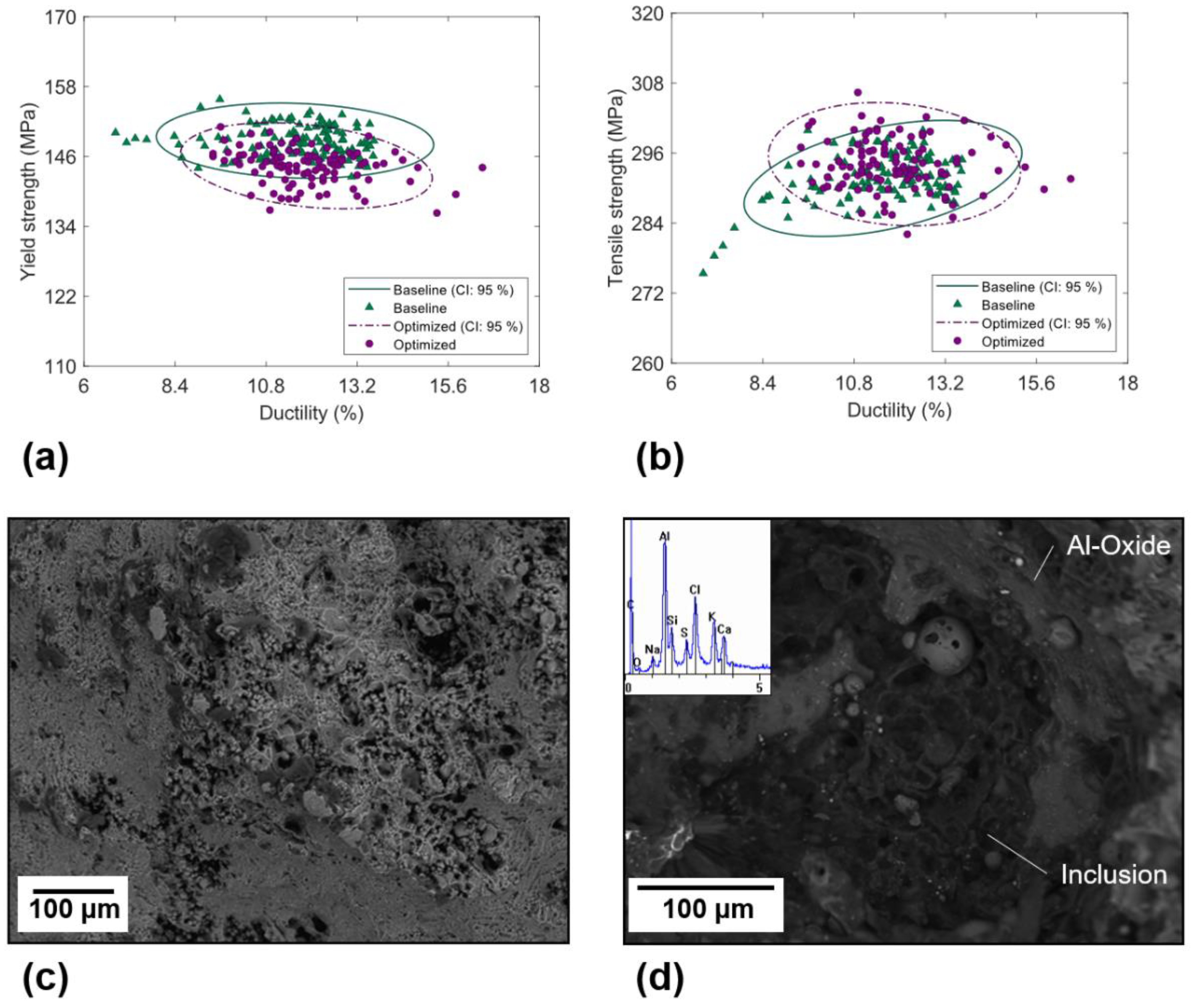

Figure 12. Tensile properties of samples produced using the (a) Baseline, and (b) Optimised plunger speed profiles; 95% confidence ellipses are shown for two-dimensional, normally distributed data. Shown in (c,d) are representative backscattered electron micrographs of pores and inclusions observed on the fracture surface of tensile specimens, respectively [13][26].
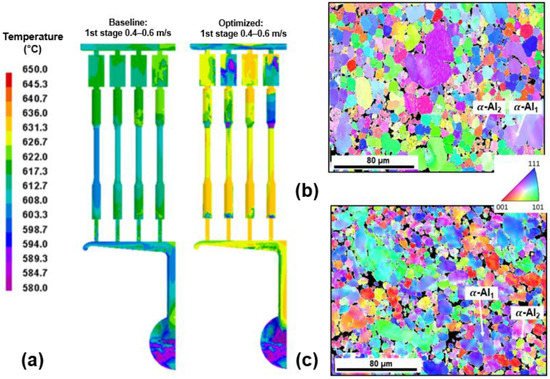
Figure 23. (a) ProCAST simulations depicting melt temperature at the end of die filling for Baseline and Optimised conditions [12][21]. Shown in (b,c) are EBSD IPF maps taken from the centre of the gauge length of tensile specimens produced under Baseline and Optimised conditions, respectively, showing primary α-Al grains nucleated in the shot sleeve (α-Al1) and die cavity (α-Al2) [13][26].
2.2. Turbulent Breakup of Non-Metallic Inclusions and Equiaxed Crystals
Members of the EPSRC Future LiME Hub have investigated the effect of die design on microstructural development and defect formation in the HPDC process. By altering the design of the runner system, Lordan et al. [19][32] were able to produce die-cast specimens under different flow field intensities. Figure 34a shows the rate of turbulent energy dissipation along the flow path of the studied dies. Higher rates of turbulent energy dissipation were observed in the lean runner system (LRS) compared to the conventional runner system (CRS). In addition, the melt experienced this high energy flow for a prolonged period in the LRS due to the increased pipe length. X-ray tomography was used to characterise inclusions in die-cast samples produced using the two dies. Figure 34b,c show plots of compactness vs. size for inclusions identified in the CRS and LRS samples, respectively; the insets of Figure 34b,c show three-dimensional visualisations of inclusions in each sample. Inclusions in the LRS sample were on average smaller in size, and more compact in morphology, than those in the CRS sample. For example, the average diameter of inclusions in the LRS and CRS samples were 0.09 ± 0.03 mm (max. 0.37 mm) and 0.15 ± 0.08 mm (max. 0.73 mm), respectively. Inclusions were also distributed more uniformly in the LRS sample than in the CRS, as shown by the insets in Figure 34b,c. A multivariate Gaussian mixture model (GMM) was used to identify species of inclusions contained within each X-ray tomography dataset. Each dataset was found to comprise a mixture of non-metallic inclusions, primary α-Al15(FeMn)3Si2 phase, and β-AlFeSi phase. These non-metallic inclusions varied significantly in size (80–1000 µm) and morphology (compact to highly irregular) and were proposed to form during the pyrolysis of commercial plunger lubricants in the shot sleeve [13][26]. The researcheuthors concluded that, in a turbulent flow, large non-metallic inclusions are broken down into more, smaller particles with a compact morphology. Increasing the rate of turbulent energy dissipation was shown to promote breakage, leading to an increase in tensile strength (+16% [19][32]) and tensile ductility (+68% [19][32]). Breakage is illustrated by the probability density (PDF) contours in Figure 34b,c, which show that the peaks of the GMM PDF move towards a region of higher compactness and lower diameter following an increase in the rate of turbulent energy dissipation.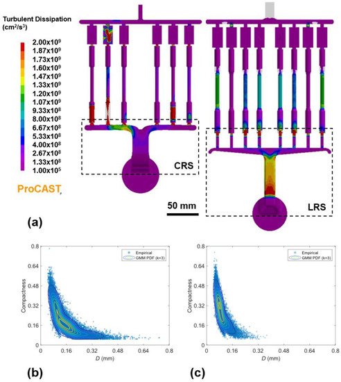
Figure 34. (a) ProCAST simulations depicting the dissipation rate of turbulent kinetic energy along the flow path of the CRS and LRS dies. Shown in (b,c) are plots of compactness vs. size for inclusion identified in samples produced using the CRS and LRS dies, respectively. A Gaussian mixture model (GMM) was used to model each dataset, with probability density (PDF) contours superimposed on the plots in (b,c). The insets (i,ii) show a three-dimensional visualisation of inclusions in each sample [19][32].
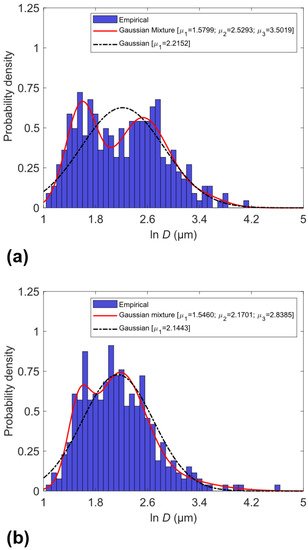
Figure 45. Maximum Feret diameter of primary α-Al grains in die-cast samples produced using the CRS (a) and LRS (b). The solid curve represents the probability density predicted from a multivariate Gaussian mixture model (GMM); the dash-dotted curve represents a simple Gaussian distribution [19][32].