Your browser does not fully support modern features. Please upgrade for a smoother experience.
Please note this is a comparison between Version 1 by Amina Tucak-Smajić and Version 2 by Catherine Yang.
Microneedles (MNs) represent one of the most promising concepts for effective transdermal drug delivery that penetrate the protective skin barrier in a minimally invasive and painless manner. Therefore, different manufacturing methods, not only for MNs but also MN molds, are introduced, which allows for the cost-effective production of MNs for drug and vaccine delivery and even diagnostic/monitoring purposes.
- transdermal drug delivery
- microneedles
- microneedle arrays
1. Materials
The advent of microfabrication manufacturing technology in recent decades has enabled the development of MNs in research laboratories and pharmaceutical companies [1][69]. Therefore, it is necessary to select the most suitable materials for MN production based on the following criteria [2][70]:
-
gentle manufacturing without damaging sensitive and unstable molecules;
-
controlled or immediate drug release; and
-
sufficient mechanical strength for skin penetration.
The first solid MNs were made of silicon [3][30], as industrial high-precision microelectronics tools and silicone flexibility enabled the production of MNs. However, their main disadvantage is the breakage of the silicon MN due to their brittle nature. Nowadays, MNs come in a variety of shapes and sizes, as well as materials, including stainless steel [4][5][6][22,71,72], titanium, nickel-iron, glass [7][8][40,44], and ceramics [9][73]. Metal MNs have sufficient mechanical strength to penetrate the skin, but their disadvantage is that they generate potential biological waste [10][11][8,10]. Interestingly, nitinol is used in vascular surgery due to its advantages in terms of elasticity, shape-memory capability, and biocompatibility [12][74]. However, polymeric MNs have better solubility and usage in case of the tip breaking [13][75]. Water-soluble polymers [11][14][15][16][10,76,77,78] and engineering plastics such as CMC, poly (glycolic acid) (PGA), polylactic-co-glycolic acid (PLGA), poly (vinyl alcohol) (PVA), poly (vinylpyrrolidone) (PVP), polylactic acid (PLA), chondroitin sulfate, and polycarbonate are employed for MN production, whereas dissolving MNs are composed of sugars such as maltose [17][18][79,80], dextran [19][81], or galactose [20][21][22][23][31,82,83,84].
The selected material determines the manufacturing MN method that should be accurate, reproducible, robust, and precise [24][107]. The manufacturing methods for solid or hollow MNs, described in the following sections, include MEMS, lithography methods, laser cutting, laser ablation, metal electroplating, isotropic and anisotropic etching [25][92], injection molding [26][108], DAB method [27][109], surface/bulk micromachining, polysilicon micromolding [28][110], and additive manufacturing (AM) technologies (FDM [29][111], stereolithography (SLA) [30][31][32][47,112,113], digital light processing (DLP), and 2PP [33][114]). Additionally, the coating of MNs with a formulation that contains APIs is described in detail below.
2. Microneedle Production Methods
2.1. Microelectromechanical Systems (MEMS)
Solid and hollow MNs, as well as molds for dissolving MNs, have been manufactured directly from a suitable material substrate using MEMS methods [20][31]. The production involves a precisely controlled three-step process: deposition, patterning, and etching of materials (Figure 13) [2][34][70,115]. Complex three-dimensional (3D) structures are, therefore, formed due to differences in the selectivity to the etchant between different materials [34][115].
In the first step, a film with a thickness between a few nanometers and 100 μm is formed on a substrate by a chemical (CVD) or physical vapor deposition (PVD) [2][35][36][70,116,117]. In the PVD process, the film is formed by atoms transferred directly from the source to the substrate through the gas phase. In the CVD process, the chemical reaction on the substrate surface results in film formation [36][117].
Then, a two-dimensional master pattern of the desired material is transferred from the original photomask to the photosensitive-coated substrate during the second phase of the process, called patterning. In most cases, a silicon wafer is used as a substrate, and the transferring process is made using a radiation source with one of the lithography process (photolithography [21][82], ion beam lithography, or X-ray lithography [15][77]) [37][118].
The most common type of lithography is photolithography, a process based on the fact that some materials such as metals are not transparent when exposed to UV light (λ = 193–236 nm), while others such as glass are transparent. In this process, an optic mask, an opaque template for generating the desired pattern in a wafer, is created (Figure 13). The mask, which consists of a quartz plate or flat glass, allows light to pass only throughout a defined pattern [38][119]. The silicon substrate is first exposed to steam or humidified oxygen at about 900 °C to produce an oxide layer, and then, rotated and coated with an organic polymer sensitive to UV light, the so-called photoresist material [36][37][39][18,117,118]. The heat of 75–100 °C followed by UV radiation removes the solvent and forms the desired photo-resistant pattern [38][119]. In this step, two types of resist, positive and negative, can be used. In the positive resist, the chains of the photo-resistant polymer break up after exposure to UV light, making them more soluble in the chemical solution—the developer, in comparison to the negative resist, where the chemical bonds are strengthened (Figure 13) [39][18].
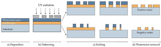
Figure 13. Manufacturing of MNs using photolithography [36][117]. (a) Deposition: As a substrate, Si wafer is exposed to steam or humidified to produce the wafer with an oxide coating. Then, the photoresistive material is spin-coated onto a substrate. (b) Patterning: Mask guided UV radiation is exposed to the photoresistive material. (c) Etching: soluble resist material is removed and SiO2 film etched. (d) Photoresist removal: in this step, the photoresist layer is removed.
Photolithography also enables manufacturing molds for MNs. In this case, a rigid silicone mold with a positive image is made, and then, a negative mold from poly (dimethylsiloxane) (PDMS) is followed by the application of the chosen material [36][117].
The etching is achieved by applying a strong acid or caustic agent to etch out the uncovered parts of the substrate to form a design on the surface of the material. Two types of etching can be distinguished: wet and dry etching [2][70]. In the wet etching process, to produce metallic or silicon MN arrays, an excess of material is removed by submerging the substrate in the chemical liquid. The etching can be performed at the same (isotropic etching) or different rates (anisotropic etching) [2][22][70,83].
On the other hand, the dry etching process is achieved by using a vapor phase or plasma etcher. Two main types of dry etching are distinguished: reactive ion etching (RIE) and ion-beam milling (IBM). In the RIE process, the gas excitation into a reactive state enables a reaction between the gas and the substrate. The number of ions that influence the degree of isotropy can be adjusted by controlling the gas pressure. The electric field can accelerate ions and further increase the direction of etching. In the case of the IBM process, inert ions are speeded up from a source to physically remove the material to be etched [39][18]. Although RIE creates structures, the etching rate is low and it is challenging to maintain a high width-to-height ratio. Deep reactive ion etching (DRIE), often called the Bosch process, is suitable for the production of off-plane MNs. This method is used to produce hollow MNs with a lumen of several hundred micrometres (width to height ratio of 30:1) [23][84]. Although wet etching can reduce fabrication costs compared to dry etching, the best results are achieved by combining isotropic dry and anisotropic wet etching to produce well-defined and sharp MN tips [20][23][40][31,84,120].
2.2. Laser Cutting
Metal MNs can be manufactured by 3D laser cutting [4][6][41][42][43][44][22,25,51,72,93,94], laser ablation [45][46][47][95,96,97], and electroplating or electroless plating of metal onto positive or negative MN molds [20][31].
Arrays of solid MNs are produced by cutting stainless steel or titanium sheets in the shape of MNs with an infrared laser (Figure 24). The desired shape, geometry, and dimensions of MNs are created using some of the computer-aided design (CAD) software. The laser beam follows the predetermined shape of the needle, then MNs are cleaned in hot water and bent at 90 degrees, vertically from the plane of the base. In order to deburr, reduce the thickness of MNs and sharpen the tips, MNs are subsequently electropolished, washed, and dried with compressed air. This manufacturing method can be used to produce a single row of MNs of different geometries, as well as two-dimensional rows of metallic MNs [4][6][41][42][43][44][22,25,51,72,93,94].
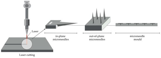
Figure 24.
Principle of manufacturing of MNs (in-plane and out-of-plane) and MN molds by the laser cutting.
Furthermore, the production of hollow MNs [48][105] and molds for a dissolving MN patch is reported [49][121]. In the first case, a KrF laser (λ = 248 nm) was used to make holes from the side of PLA sheets, which had previously been manufactured using a micromolding technique [48][105].
2.3. Laser Ablation
This method is a top-down method for processing materials, including metals. Light pulses give the bulge of the desired shape on a metal plate, thus forming solid metal arrays [45][95]. However, due to the high-intensity laser pulses, the formation of plasma of ions and electrons is not suitable for the fabrication of structured materials. Omatsu, therefore, introduced a novel, time and cost-effective fabrication method of manufacturing metal MNs based on circularly polarized optical vortices that have nonzero total angular momentum, as shown in Figure 35. The authors reported on the fabrication of a tantalum MNs with a vertical height of over 10 µm and significantly small tip radii [46][96].
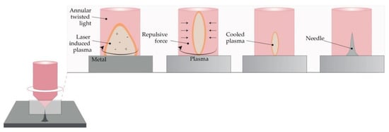
Figure 35. The principle of metal MN fabrication using twisted light with a spin by Omatsu et al. (Modified from [46]).
The principle of metal MN fabrication using twisted light with a spin by Omatsu et al. (Modified from [96]).
2.4. Micromolding Method (Solvent Casting)
Dissolving MNs are usually produced by filling a previously prepared MN mold with the liquid formulation [50][89]. Generally, the mold is made from a silicon wafer as a starting material [11][10]. Afterwards, the wafer is oxidated at 1000 °C. A needle geometry is patterned using lithography methods, followed by RIE, while CVD is used for coating a wafer. A liquid polymeric solution is poured into prepared molds, and then, air voids are removed with vacuum or centrifuge [51][52][32,106]. Subsequently, the molds are dried in the oven, and MNs are removed after cooling (Figure 46) [28][110]. The advantages of this method lie in the relatively simple, cost-effective MN production at an ambient temperature [39][18]. Also, the production of biodegradable polymer MNs, consisting of both natural and synthetic materials, with an appropriate geometry and sufficient strength to penetrate the skin, is reported [11][53][10,34]. Interestingly, micromolding has even been used for the production of ceramic MNs [44][94].
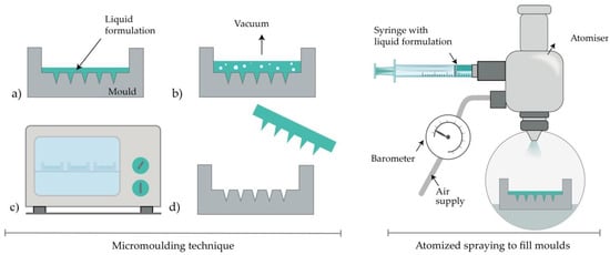
Figure 46. Left: MN production with micromolding (left) consisted of (a) pouring the liquid formulation, (b) vacuum degasification, (c) drying and (d) removal of MNs from the mold. Right: Atomized spraying to fill molds.
2.5. Atomized Spraying Method
This method overcomes the problems associated with the limited capacity for mass production of dissolving MNs with the desired geometry and physical characteristics. Also, the problems linked to the effects of liquid surface tension and viscosity when filling the MN molds can be minimized. Dissolving MN can be produced from the sugars (trehalose, fructose, and raffinose) or polymers (PVA, PVP, CMC, HPMC, and sodium alginate). Briefly, a nozzle connected to an air source and liquid formulation produces an atomized spray (Figure 46). The formulation is filled in PDMS molds and dried for 2h at ambient temperature. Laminate-layered and horizontally-layered dissolving MN can also be produced by this method [54][101].
2.6. Droplet-Born Air Blowing Method (DAB)
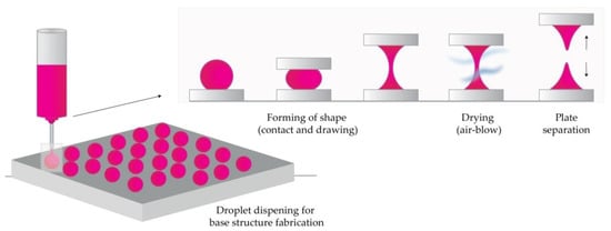
Conventional MN production methods have led to drug inactivity due to manufacturing under UV light and heat. The DAB method, proposed by Kim et al., is one of the drawing lithography methods [55][102]. This method, in which polymer droplets are shaped into MNs with the use of air blowing, enables production under mild conditions, without the use of UV radiation or heat [11][10].
In short, the process begins by dispensing the prepared solution on two plates (upper and lower), then placing the upper plate downwards to allow contact of droplets. The upward movement of the upper plate elongates the viscous solution. In the next step, air blowing removes the residual water and solidifies the droplets in the desired shape by pulling the droplet from a substrate, as illustrated in Figure 57 [27][55][56][57][102,109,122,123].
The application of one drop of polymer per MN, therefore, enables direct control over the size of drops and the concentration of API. This 10-minute process was used to produce insulin-loaded dissolving MNs that successfully lowered blood glucose levels in diabetic mice [27][109].
A novel method that uses a shadow mask enabled a uniform MN production, and it overcame low throughput-associated problems in the droplet formation. Using this method, the authors reported controlled drug dosage with optimization of hole width and thickness of the shadow mask [55][102].
2.7. Pulling Pipettes
This method is suitable only for hollow glass MNs. Two research teams produced glass MNs by pulling fire-polished borosilicate glass pipettes exposed at a high temperature with a micropipette puller and beveler [8][58][44,86]. Hollow MNs provided an effective delivery of bolus insulin to patients with type 1 diabetes [8][44]. Overall, it was concluded that glass MNs could infuse millilitres of fluid into the skin [58][86]. MN produced by this method successfully delivered 6-aminoquinolone and Rose Bengal to the eye, thus enabling intraocular drug delivery in a less invasive and less painful manner than macroscale hypodermic needles [59][87].
3. Additive Manufacturing (AM)
Additive manufacturing, more commonly known as 3D printing, represents a new field of research for the manufacturing of MN arrays and molds. The first step in all AM technologies is the design of a 3D object with computer-aided design software (CAD). In the second step, the CAD model is converted to an STL file to tessellate the 3D shape and slice it into digital layers. The STL file is then transferred to the printer using custom machine software, and the printer is set-up with printing parameters. The printer builds the model by fusing or depositing proper material (e.g., ceramics, liquids, thermoplastic, plastic, photopolymer, powders, or even living cells) in layers [60][61][62][63][64][65][66][124,125,126,127,128,129,130].
Additive manufacturing technologies, FDM, [67][68][103,104], photopolymerization-based techniques such as SLA [30][31][32][69][70][71][72][47,112,113,131,132,133,134], DLP [73][74][75][76][135,136,137,138] and 2PP [33][77][78][79][100,114,139,140] were successfully employed in the fabrication of MN arrays. These cutting-edge technologies have numerous advantages over traditional manufacturing approaches including simplicity, low cost, the ability to fabricate complex geometrical products including changes to the original designs at any time, and the production of patient-specific devices [65][80][129,141].
3.1. Fused Deposition Modelling (FDM)
The preparation for printing MNs with typical FDM printers starts with designing MNs using CAD software and optimizing its geometry according to the printer specification [62][66][126,130]. Then, the suitable thermoplastic material, in the form of a filament, is fed into the printer by rollers, where it is heated to just above its softening point (glass transition temperature Tg) by heating elements into a molten state. The melted or softened material, guided by gears, is moved towards the head end where it is extruded from the printer’s head, through a nozzle and subsequently deposited layer-by-layer on a build plate, cooling and solidifying in under a second (Figure 68) [60][61][62][63][124,125,126,127]. The printer’s head moves within the x- and y-axes, whereas the platform can move within the z-axis, thus creating 3D structures [65][129].
Standard filaments used in FDM printers are acrylonitrile butadiene styrene (ABS), PLA, PVA, high impact polystyrene (HIPS), polyethylene terephthalate glycol-modified (PET-G), and nylon, while the dimensions of filaments adopted in the commercially available print head are in the range of 1.75 mm and 2.85–3 mm [62][126].
Processing parameters that should be optimized during an FDM process include nozzle diameter, feed rate, the temperature of both the nozzle and the building plate, printing speed, the height of the layers, and part built orientation [63][65][127,129].
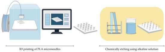
Although FDM is a versatile and cost-effective MNs manufacturing method, its main limitation is low printing resolution. Luzuriaga et al. reported for the first time combination of FDM with a post-fabrication etching step to obtain ideally sized and shaped needles [68][104]. Camović et al. also successfully used FDM to print MNs, which were subsequently coated [67][103] (Figure 68).
3.2. Stereolithography (SLA)
With its high resolution and accuracy, as well as smooth surface finish, SLA is the most commonly used technology for printing MNs. Ovsianikov et al. were the first to report that the lithography-based multiphoton polymerization 3D printing method can be used to create MN arrays for transdermal drug delivery [9][73]. This method is based on the photopolymerization of liquid resin with photo-active monomers by UV light. MNs are built by solidification of subsequent layers of resin in the presence of high energy light, e.g., UV laser beam guided by scanner mirrors [62][126]. MN pattern is created by a laser beam on the surface of a resin, which causes the resin to have definite depth. To remove unpolymerized resin residues, MNs are washed in an alcohol bath and then cured in the UV chamber [32][71][113,133].
Although SLA prints high-quality parts at a fine resolution (range of 10 μm), this method is relatively slow, expensive, and the range of printing materials is very limited (lack of biocompatibility) [81][142]. Many research groups reported using this photopolymerization-based technique in MNs manufacturing, to obtain solid MNs, hollow MNs [30][47], and MN molds [69][131]. Pere et al. and Economidou et al. employed SLA to fabricate MN arrays using a Class 1 biocompatible resin, with excellent mechanical strength, which was coated with insulin–sugar films [32][71][113,133].
3.3. Digital Light Processing (DLP)
DLP is also a photopolymerization-based technology based on the ability to polymerize photosensitive polymers through projections of light. This method is faster than SLA, and a high definition projector flashes the entire cross-section of the object at once, in the form of volumetric pixels [60][124]. Gittard et al. reported that DLP could be used in MNs fabrication. In their study, they successfully employed DLP to print solid MN array structures in various geometries out of an acrylate-based polymer for wound healing applications [73][135]. El-Sayed et al. also successfully used a desktop DLP 3D printer for MNs molds for nanoparticle delivery [75][137]. Lu et al. fabricated drug-loaded MN arrays for the transdermal delivery of a chemotherapeutic drug using microstereolithographic (DLP) apparatus.
3.4. Two-Photon-Polymerization (2PP)
2PP method enables the low-cost, layer-by-layer fabrication process of 3D structures from solid, liquid, or powder precursors in the microscale and nanoscale structures. A femtosecond or picosecond laser is focused inside a liquid resin droplet for the polymerization into MN structure [45][60][95,124]. The process is based on the temporal and spatial overlap of photons to achieve photopolymerization [77][100]. The advantages of the process encompass a high level of flexibility, scalable resolution, improved geometry control, and also, the process can be performed in conventional facilities [45][60][95,124].
Doraiswamy et al. first reported using 2PP to produce MNs from Ormocer® (organically modified ceramic) materials [82][85]. Trautmann et al. reported using 2PP to fabricate hollow MNs combined with internal laser-generated microchannels [78][139]. Another research group also printed ultra-sharp polymer MNs via 2PP [79][140].
Cordeiro et al. described an approach to fabricate high-quality MN array master templates using 2PP 3D [33][114]. Gittard et al. suggested that 2PP can create MNs with a wide range of geometries (in-plane, out-of-plane, rocket-shaped, and mosquito fascicle-shaped MNs) [77][100].
4. Microneedle Coating Techniques
Solid MNs can be coated with the drug-containing dispersion, which provides a rapid drug release from the coating into the tissue [83][143]. Depending on the way that the physical contact between MN and drug-containing dispersion is achieved, some methods imply the selective coating of the MN shafts only while other methods include the coating of both the shafts and the base of substrate. Minimal drug loss, better control over drug dosage, and efficient delivery can be accomplished if the MNs are selectively coated. Good quality of coating, reproducible coating process, and efficient delivery are three factors that play a main role in providing versatile application of MNs [84][144].
However, it is hard to achieve a suitable drug release profile because of the limited surface where the drug can be inserted, which is caused by specific MN’s structure. Problems with stability, uniformity, consistency, and reproducibility may also occur. During the coating process, the drug can be lost from the MN surface. The non-uniform coating thickness of the drug on the MN surface may lead to inaccurate dosing. All those drawbacks should be considered when choosing the right method for coating MNs with drug-containing dispersion [83][143].
4.1. Dip-Coating
Dip-coating is a method that selectively coats the MN shaft without contaminating the base substrate of the MN array by immersing MNs in drug formulation. Different aqueous, organic solvent-based, or molten liquid can be used. Dipping results in forming a liquid film on the MN surface followed by drying where the adherent liquid film is converted into a solid coating [38][83][119,143]. The viscosity and surface tension of the coating solution should be adjusted carefully to prevent the rising of coating solution upon the MN shaft to the base substrate. The selective coating of the MN shaft can be achieved by masked dip-coating or thin-film dip-coating. Masked dip-coating implies the use of a masking plate, which disables the passing of the coating solution to the base substrate [85][145]. In thin-film dip-coating, the thickness of the coating solution is lower than the height of the MN, which assures the insignificant capillary rise of the coating solution and, therefore, prevents possible contact between coating solution and base substrate [38][119].
The drug amount that is coated on the MNs is dependent directly on the thickness of the coating on the MN shaft. The higher thickness and drug mass can be achieved by raising the speed at which MNs exit the coating solution, enhancing solution viscosity and increasing the number of dipping. Adding surfactants ensures uniform and integrated coating and decreases the surface tension of the solution. Drying time between dips also impacts the coating thickness [84][144].
Simple fabrication process and low costs make dip-coating a very convenient method for MN fabrication. Optimal drug delivery can be achieved by upgrading the method with a dam board, a roller, a fixture, and a limit [86][146]. The main drawback of this method is slow drying that can cause loss of drug dispersion from the surface of MNs. Also, surface tension can obstruct the uniform coating of the individual MNs if they’re closely spaced [38][119].
Solid MNs were fabricated from stainless steel using laser cutting and electropolishing. Then, suitable concentrations of CMC and Lutrol F-68 NF were used to increase viscosity, decrease the surface tension of the coating solution, and avoid contamination of the base, with micron-scale control over the length of the coated shaft. The MNs were coated with vitamin B, calcein, bovine serum albumin, plasmid DNA, and viruses [4][22]. Titanium MNs, dip-coated with recombinant human growth hormone, provided similar absolute bioavailability as commercial subcutaneous injections. The authors concluded that the lack of pain and ease of administration might lead to the replacement of these injections with MN patches [87][99].
MNs coated with vaccines should be targeted to skin immune cells where the preservation of protein integrity is important because a change in protein structure can lead to impaired vaccination efficacy and an altered immune response [88][46]. MN bases were coated with an assembly of DNA vaccines, pH-responsive copolymer, and heparin. The release of vaccines was enabled by electrostatic repulsion between co-polymer and heparin [89][147]. DNA vaccines have an intracellular encoded antigen, which is presented directly to essential effector cells for cytolytic activity. MNs provide penetration through the epidermis of the skin to deliver DNA vaccines to the resident antigen-presenting cells within the dermis. They also enable intracellular co-delivery of DNA vaccines by using polyelectrolyte multilayers with adjuvant materials [90][148]. The main disadvantage of MNs coated with DNA vaccines is poor coating efficiency and immunogenicity. Nano-patterned MNs improved the affinity of stainless steel for plasmid DNA and consequently enhanced vaccine efficiency and its immune response. Nano-patterned MNs had better dip-coating efficiency and DNA vaccine loading capacity because of their more hydrophilic surface. Better cytocompatibility was accomplished according to higher cell proliferation. Most importantly, they had a higher level of cellular immune responses [91][149].
Antigen activity can be decreased when influenza vaccine is coated on MNs. CMC increased viscosity but also contributed to vaccine activity loss due to virus particles aggregation. Replacing CMC with trehalose assured protection of the antigen and its activity due to blocked particle aggregation and better thermal stability [92][150].
Layer-by-layer coating represents a modified dip-coating method. Electrostatic interactions are used to create a layered coating on the MN surface, unlike the classic coating method where the coating is based on the viscosity of the solution. In the case of DNA or protein molecules, the solution contains negatively charged DNA and positively charged polymer, which leads to the formation of a polyelectrolyte multilayer on the MNs. Chemically modifying the MN surface or precoating multiple alternate layers of negatively and positively charged polymers is necessary to acquire the desired charge polarity [93][151].
Drop coating is another modification of the dip-coating method. It implies dropping the coating solution on the MN array instead of dipping the MN array into the solution. Slow solvent evaporation leads to a non-uniform coating of the MNs and the base, liquid segregation from the MN tip, and substrate accumulation between MNs. It leads to the stage where the mostly coated area is the base. These drawbacks can be exceeded by heating the patch or drying under vacuum [94][152].
4.2. Gas-Jet Drying
Gas-jet drying is a method where the drug suspended in a coating solution gets transitioned into the gas phase using a gas-jet applicator (Figure 79) [95][153]. It is suitable especially for curved MNs, because the slow drying process, specific for dip-coating, is not convenient in this case. Wet coating liquid on the surface of the MNs has the potential to move and change its thickness and, consequently, the dose accuracy. This method is also appropriate for small (<90-micron length) and very closely spaced (~20,000 cm−2) MNs [96][154].
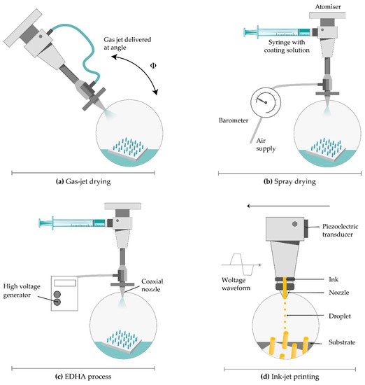
Figure 79.
Coating techniques for MNs. (
a
) gas-jet drying; (
b
) spray drying; (
c
) electrohydrodynamic atomization (EHDA) processes; (
d
) ink-jet printing.
Solid silicon microprocjections were coated with a thin layer of gold. The solution, with ideal surface tension and viscosity, including methylcellulose, surfactant and model drug, is coated on the whole length of the microprojection. Drying started with a gas jet at 6–8 m/s and incident angle of 20° horizontally to direct the coating liquid onto the MNs and away from the base. The thickness of the coated layer on microprojections was 5 µm and increased rapidly to allow the coated material to dry instead of relocating on the base substrate. This method offers several advantages including uniform distribution and fast drying of the coating solution, more or less constant viscosity of the bottom layer of the solution, and the possibility of removing the excess coating solution from the base substrate [97][155].
The improved delivery of large vaccine molecules, through the SC, can be achieved by modifying the gas jet method for coating MNs. Raising the incident angle from 20° to 70°, removing the patch edge, and rotating the patches during the coating process ensured the uniformity and relocation of the drug from the whole MNs only to the tips. Much lower doses provided an equivalent protective immune response as the intramuscular injection. These MN patches also contributed to extended and improved vaccine stability [98][156].
4.3. Spray Coating
Spray coating implies using fluid pressure to create droplets. An intact film-coat is formed from fine droplets (<280 µm), which are deposited on MN array and then, outspread and coalesced. The first step is atomization, which generates fine droplets (Figure 79). Then comes the deposition and adherence of droplets, which collide on the surface. The last step is a coalescence of droplets on the substrate to form an intact film coating [99][64].
The nozzle design, concentration, input ray, physicochemical characteristics of the coating solution (viscosity, surface tension, and density), and processing parameters like air-to-liquid mass ratio, the duration of spraying, atomization air pressure, gun-to-surface distance, and air cap setting determine the droplet size. The deposition of droplets on the surface is determined by spray velocity and spray density [99][64]. The spray coating process can be used for the efficient application of an intact, micron-sized film-coating on silicon MN arrays as well as the production of dissolved MNs.
4.4. Electrohydrodynamic Atomization (EDHA)
Electrohydrodynamic atomization (EHDA) is a production method of atomized droplets by a moving liquid where charge inside the droplets is generated by the electrical field. When the critical voltage is achieved, liquid spurts out of a nozzle in the form of droplets. Then, it is deposited onto a grounded collector positioned below the nozzle tip (Figure 79) [100][157]. The coating liquid contains a solvent, polymer, and drug. EHDA can generate particles (electrospraying) and fibres (electrospinning). This method provides coating the MN tips only, without coating the base substrate due to insulating polymeric masks. Still, there is a lot of drug wastage on the mask upon the base substrate [101][158].
The EHDA process can be single needled (formulation is injected into a single nozzle by syringe pump), coaxial (two or more immiscible liquids are put in separate nozzles), and multiplexed (formulation is put in a single or coaxial nozzle array). The coaxial system protects the drug from direct exposure to the environment and enables sustained and controlled drug release [96][154]. Flow rate, voltage, and distance between the nozzle and collecting platform and solution viscosity and surface tension have a significant influence on particle size, size distribution, porosity, shape, and surface charge. The material characteristics affect jet stability. The most important requirement for the EHDA process is a low electrical conductivity of the solvent [101][158].
This method is used for the delivery of insulin, folic acid, titanium dioxide antimicrobial agent, gold used in gene delivery, and sensitive biomolecules like peptides and proteins, which are unstable when administrated orally [101][102][158,159]. Ali et al. coated MNs with particles and fibres through the EHDA process. They concluded that MNs with PVP in ethanol showed more rapid release compared to a sustained release profile of MN coated with polycaprolactone in dichloromethane. Both types of MN successfully penetrated through the skin, and the electrospun MN coating released a large amount of the loaded drug within 6 h [103][160].
4.5. Piezoelectric Inkjet Printing
Piezoelectric inkjet printing provides a controlled and precise MN coating with liquid droplets (1–100 pl), which is followed by solidification. The method is compatible with different aqueous and organic solvents. The low viscosity of the formulation is preferable to prevent clogging the small jetting nozzle. The voltage supplied material connected to a piezoelectric transducer produce vibrations to eject drops from the nozzle [104][162].
A modified method called thermal inkjet printing implies drop production by increasing the formulation temperature a bit higher than its boiling point (Figure 79) [104][162]. The pressure pulse in the ink chamber made by an electric field distorts piezoelectric crystal and force drops ejection from the nozzle. The nozzle dimensions determine the droplet size. The coating deposition is mainly dependent on nozzle size, applied voltage, and pulse duration [105][163]. The variation of this continuous inkjet printing is dropped on-demand printing. It implies liquid ejection from a printhead only when a drop is required [106][164].
This method provides coating MNs with poorly soluble drugs. Biodegradable PGA MNs were coated with voriconazole and showed antifungal activity [107][165]. The transdermal delivery of 5-fluorouracil, curcumin, and cisplatin can be achieved by metallic MN produced by piezoelectric inkjet printing. Drug solubility directly affected the release profile and concentration affected antiproliferative activity [105][163]. Although piezoelectric inkjet printing has advantages regarding dip-coating, such as improved accuracy, reproducibility, reduced waste, scalability, and its amenability for continuous manufacturing, this method is limited by the available MN surface area that can be directly targeted for printing [108][166].
5. From Clinical Trials to Commercial Development
Up to now, MNs with a broad range of geometries, with or without a MN application device, have been fabricated using different manufacturing methods from a variety of materials. Although MNs have been extensively studied for transdermal drug delivery and vaccine delivery, these systems can also be designed for delivery targeted to other tissues such as oral mucosa, vaginal mucosa, anal sphincter muscles, and hair follicles [109][167]. Nowadays MNs are also being explored for ocular drug delivery where the drug is delivered to the cornea, sclera, and suprachoroidal space [110][168]. MNs are already in advanced development and marketed for cosmetic skincare (Dermaroller®, Dermapen®). Recently, MNs were investigated as a part of the monitoring/diagnosis system to provide the ability for at transdermal sampling of body fluids in a completely painless manner [111][169].
It is necessary to adequately select the type of MNs and their geometry in order to successfully developed the final product with sufficient and reproducible penetration for transdermal drug delivery. Usually, in order to obtain the possibility of self-administration a MN application device (manual hand-held or impact-insertion) is necessary. Many pharmaceutical companies and research laboratories are involved in the MN-based product development including 3M, Zosano Pharma, Alza Corporation, Becton-Dickinson Technologies, Valeritas, Vaxxas, Microneedle Therapy System, Nanopass Technologies Lohmann, Therapie- Systeme AG, and others.
Most of the MN devices are still in clinical trials, and only a few of them are currently available in the market. The first commercialized MN device was developed by Becton-Dickinson Technologies named Soluvia® (Figure 810A) although some authors suggest that this device does not contain truly MN arrays, but rather very short hollow needles that allow successful ID injection from a conventional syringe barrel [39][18]. Sanofi Pasteur marketed Intanza® in 2009 as the first influenza vaccine that targets the dermis [112][170]. Even though many clinical studies indicated that Intanza’s benefits are greater than its risks, in 2018 the product is withdrawn from use in the European Union at the request of the marketing authorization holder [113][171]. In February 2010, the FDA approved MicronJet® by Nanopass Technologies. This single-use MN device composed of four hollow silicon needles shorter than 500 mm in length attached to a plastic device, was used to deliver insulin, lidocaine, and influenza vaccine intradermally. In 2009, the company completed Phase 1 clinical trial with the aim of comparing glucose pharmacokinetics and insulin pharmacodynamics injected via the Micronjet® with a conventional needle for the delivery of insulin [114][172]. To improve device performance, especially the insertion technique, the company developed MicronJet600® as a new device version [115][173]. In 2019, Yonsei University completed a clinical study to evaluate the safety and immunogenicity of Bacillus Calmette–Guerin (BCG) delivery via Micronjet600® device (Figure 810B) compared to those via a conventional needle [116][174].
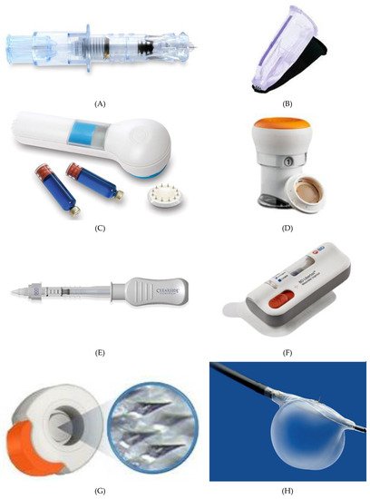
Figure 810. Current MN devices. (A) Soluvia®, (B) MicronJet®600, (C) Microstructured Transdermal System®, (D) QtryptaTM, (E) SCS Microinjector®, (F) Microinfusor®, (G) MicroCor®, (H) Bullfrog® Micro-Infusion Device.
3MTM developed the Microstructured Transdermal System (MTS) (Figure 810C) including hollow MN (hMTS) and solid MN technology (sMTS). This system consists of a coated MNs which allow water-soluble, polar, and ionic molecules, such as lidocaine, to be successfully delivered through the skin within seconds. Hollow MTS is now available for use in clinical trials, while sMTS was successfully used in Phase I and II clinical studies [117][175]. In 2019, Radius Health, Inc. started a phase III clinical study on the delivery of abaloparatide in the treatment of postmenopausal women with osteoporosis by using sMTS [118][176].
Zosano Pharma Corporation introduced their Zosano patch-coated titanium microprojections array designed for the enhanced delivery of biopharmaceuticals such as protein, peptide, vaccines, and other biologics into the skin. Recently, Zosano Pharma Corporation developed QtryptaTM (Figure 810D) (zolmitriptan intracutaneous microneedle system) for the acute treatment of migraine with or without aura in adult patients, which is currently under review by the FDA (will be available, if approved, in 2021) [119][120][177,178].
The SCS Microinjector® (Figure 810E) is Clearside Biomedical proprietary, which is composed of a syringe and two 30-gauge hollow MNs of varying lengths, each less than 1.2 millimetres used to inject a wide variety of drugs into the suprachoroidal space [121][179].
The Microinfusor® (Figure 810F), developed by Becton Dickinson (BD) Technologies, is a hollow MN system that allows delivery of a wide range of drugs to the subcutaneous tissue over a period of time. Corium’s MicroCor® system (Figure 810G) consists of dissolving MNs for an innovative, needle-free system delivery of drugs and vaccines across the skin. The company successfully demonstrated the ability to incorporate a wide range of molecules into the MicroCor® system, although the safety and efficacy of MicroCor®-based products have not yet been established [122][180].
Mercator MedSystems, Inc. developed a very interesting MN-based device named Bullfrog® Micro-Infusion Device (Figure 810H) in order to safely inject therapeutic molecules through blood vessel walls into adventitial tissues. The device is tipped with a balloon-sheathed MN. This device has received 510(k) marketing clearance from the FDA is CE Marked [123][181].
Above mentioned MNs devices, especially marketed ones, should encourage researchers and companies to move toward large-scale manufacture and design of MN devices using different novel materials and production methods.