The electrochemical stability of the metal must be taken into account before using it as the Li host in LMBs [
16]. To host the Li anode, the challenge is with Li alloying at a low potential range of 0.01–2.0 V versus Li/Li
+. Copper (Cu), nickel (Ni), and stainless steel are considered stable enough to be used as Li host materials. The initial plating of lithium on planar two dimensional (2D) substrate renders inhomogeneous Li deposition due to the inhomogeneous distribution of the electric field. The rough, cracks, and inhomogeneous Li nucleation act as hot spots, which favor the continuous deposition of Li leading to dangerous Li dendrites and mossy Li. The continuous growth of needle and whisker shaped Li dendrite growth not only challenges the safety concern of batteries but also leads to the formation of uncontrolled and undesired formation/deformation of SEI. Thus, a host with abundant Li storage sites is strongly recommended, which can provide the route for dendrite free Li deposition and accommodate the volume expansion of Li, during Li plating/stripping, even at higher current density.
Lithium
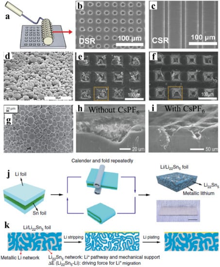
Lithium metal itself can be constructed as the Li host in the form of a nano/microstructured framework. Ryou et al. designed defects in the lithium foil using the microneedle technique shown in a to introduce high surface areas that serve as preferred sites for Li plating [
17]. The other methods of producing microstructured Li include soft lithography, where continuous surface relief (CSR) and discontinuous surface reliefs (DSR) were fabricated on the surface of the Li metal foil electrode [
18]. The continuous and discontinuous 10 μm deep surface modifications on 20 μm thin Li electrode as shown in b,c provides an effective way to replace the use of excess Li. Kong et al. pressed the Li powder with a particle size of fewer than 20 μm on stainless steel mesh d to create a porous Li-powder anode [
19]. The porous anode with 25% Li loading eliminates the growth of Li dendrites. Later, Park et al., introduced micropatterns on lithium metal using micrometer-scale pyramid reliefs (height-50 μm, width-50 μm, and ridge length-40 μm) [
20]. During stripping, the original dimension was recovered draining the liquid-like/or granular like plated Li from such structures as shown in e,f. The coating of the micrometer particle size Li powder (CLiP) on the copper foil as shown in g can also be done to improve the battery performance and replace the excess Li foil electrode [
21]. This study shows that the porous structure and high surface area of the coated/pressed Li powder significantly reduce the current density during plating/stripping. The CLiP introduced the safety and practical battery operation at a lean lithium condition.
To further enhance the self-healing electrostatic shield mechanism, Kim et al., employed an electrolyte solution containing cesium hexafluorophosphate CsPF
6 (0.05 M) into micropatterned LMA [
22]. The cesium ions form a positively charged electrostatic shield around the initial growth of protrusions, which obliges the deposition of Li adjacent to the protrusions leading to dendrite-free Li deposition [
23,
24]. h,i show the cross-section SEM image of micropatterned Li without and with CsPF
6. The micropatterned Li metal shows the uncontrolled granular Li deposition. In contrast, the micropatterned Li with CsPF
6 modifications shows the dendrite-free and stabilized Li metal anode.
Figure 1. Micropattern preparation process and Li deposition morphology on porous Li. (
a) Schematic demonstration of the microneedle technique. Reproduced with permission from [
17], John Wiley and Sons, 2014. (
b,
c) SEM images of continuous surface relief (CSR) and discontinuous surface relief (DSR) on the Li electrode. Reproduced with permission from [
18], American Chemical Society, 2019. (
d) SEM image of the Li-powder electrode. Reproduced with permission from [
19], Institute of Physics Publishing, 2012. (
e,
f) SEM images of Li plated and stripped. Reproduced with permission from [
20], John Wiley and Sons, 2016. (
g) SEM image of the coating of the micrometer particle size Li powder (CLiP) electrode
. Reproduced with permission from [
21], John Wiley and Sons 2013. (
h,
i) Cross-section SEM images of patterned Li without and with CsPF
6. Reproduced with permission from [
22], Elsevier, 2018. (
j,
k) Schematic illustration of the preparation and Li plating/stripping on the Li/Li-Sn composite electrode. Reproduced with permission from [
25], Springer Nature, 2020.
The battery operation at a higher rate demands low effective current density and fast lithium-ion diffusion kinetics. The nanostructured electrode lower effective current density and the lithium-containing alloys can facilitate the faster lithium-ion diffusion. Recently, Wan et al. reported an interpenetrated 3D lithium metal/lithium tin alloy nanocomposite by a simple calendaring and folding route and lithium-tin alloying reaction mechanism as shown in j [
25]. The schematic of dendrite-free Li deposition during plating/stripping cycles achieved with such lithium and the lithium-tin alloy is shown in k. The strong anchorage affinity between lithium and lithium–tin alloy leads to low interface impedance and dense structure [
1]. The potential difference between lithium and lithium–tin alloy and abundant interfaces enable ultrafast Li-ion diffusion across the entire LMA electrode. As a result, the lithium metal/lithium tin alloy nanocomposite anode delivered stable lithium plating/stripping cycles at 30 mA cm
−2 and 5 mAh cm
−2 for 200 cycles. The full cell configuration with LiNi
0.6Co
0.2Mn
0.2O
2 (NCM) cathode exhibited an outstanding rate capability of 74% at 6 C compared to its initial capacity (167 mAh g
−1 at 0.5 C) and with LiFePO
4 (LFP) cathode demonstrated capacity retention of 91% at 5 C after 500 cycles, respectively.
Copper
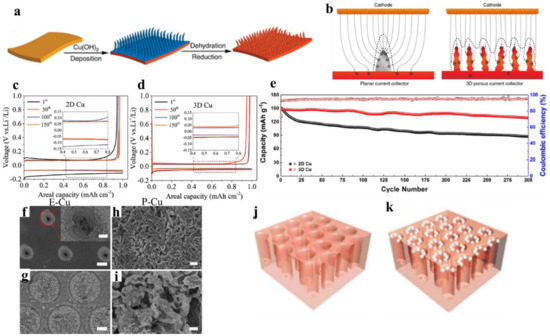
The 3D nanostructured copper with a high electroactive surface area is considered as an appealing Li host matrix. Such a framework can lower the current density and provide the room to accommodate the Li and manipulate the electric filed for guiding the Li deposition. To synthesize 3D Cu porous nanostructure, Yang et al. reported the simple solution-based approach with a submicron framework (median pore size 2.1 µm) by immersing the planar Cu foil in ammonia solution [
9]. a shows the schematic representation of preparing 3D porous Cu from the planar Cu. b shows the lithium-ion flux in planar and 3D porous Cu. In planar Cu, the irregular, rough, and cracks act as a local hotspot for Li-ion accumulation. The Li metal deposition is amplified at those Li-ion accumulation centers with higher plating cycles, which leads to the growth of Li dendrites. The high surface area of Li dendrite consumes an excess amount of electrolyte and Li leading to poor CE and quick capacity fading. Besides, the dendritic Li can pierce the separator, which can cause a short circuit or fire caught, threatening the safety concern of batteries. In contrast, 3D porous Cu has uniformly distributed the Li-ion flux due to the numerous and uniform protuberant tips on the submicron fibers. As a result, the deposited Li fills the pores evenly without any Li dendrites. The high pore volume of the structure can provide sufficient room to accommodate Li that leads to the stable and reversible Li plating/stripping. As a result, the 3D porous Cu showed plating/stripping cycles for 600 h with low voltage hysteresis (<50 mV) at 0.2 mA cm
−2 and exhibited a CE of 98.5% at 0.5 mA cm
−2. Further Li deposition behavior study on 3D Cu foam with an average pore size 170 µm showed that Cu foam does not have any effect of the Li space constraint. This led to the Li metal detachment from the backbones of the Cu foam causing electric disconnection, which induces Li dendrite growth. Lu et al. reported a free-standing 3D Cu nanowire (CuNW) network membrane via reducing copper nitrate in the NaOH aqueous solution [
26]. The voltage hysteresis was further lowered to 40 mV and the CE, which reached 99.2% after 50 cycles remain stable to 98.6% after 200 cycles at 1 mA cm
−2. The full cell coupled with the LiCoO
2 cathode shows an outstanding 30% increase in the specific capacity at 5 C indicating the advantage of the Li-CuNWs nanocomposite in LMBs at a higher rate.
The dealloying mechanism such as the dissolution of zinc (Zn) out of brass (Cu-Zn alloy) using various chemical-solution and vacuum distillation processes results in the formation of voids and microstructures [
27,
28,
29]. The porosity can be easily tuned by adjusting the etching condition (such as the concentration of the solution, distillation temperature, and time) depending upon the method used. The interconnected, uniform, and smooth porous Cu provides sufficient electrical conductivity, uniform Li-ion flux, and space for Li accommodation. Besides, 3D porous Cu exhibited the lower voltage hysteresis as shown in c,d, and improved cycling performance with a capacity retention of 87.2% after 300 cycles of charge/discharge at 50 mA g
−1 as shown in e [
28,
29].
The vertically distributed electric field promotes the vertical growth of Li dendrites, which continues to grow towards the separator and cathode and eventually pierce the separator causing short-circuits. To address these issues, it is necessary to constrain the lithium dendrite growth within the porous scaffold and distribute the electric field in the lateral direction. For this, the compartmented and the vertically aligned (VA) 3D porous Cu have been designed by the laser microprocessing system, and a series of processes, including hot lamination, laser ablation, and alkaline etching treatments. Zou et al. developed compartmented 3D Cu (150 μm diameter) by an industry-adaptable technology following a series of processes, including hot lamination, laser ablation, and alkaline etching treatments [
30]. The insulating polyimide (PI)-clad copper grid with lateral electric field distribution designated as E-Cu guides the Li deposition laterally within the porous scaffold of Cu (f,g). In contrast, pristine copper (P-Cu) showed larger, thicker dendrites with an uneven surface as shown in h,i. Wang et al. used a laser microprocessing system to design VA microchannels with optimized pore radius, pore depth, and pore spacing of 5 µm, 50 µm, and 12 µm, respectively [
31]. The VA porous Cu provides a large surface area to deposit the lithium in the microchannels as shown in j,k. The VA porous Cu demonstrated a stable CE of 98.5% for 200 cycles and voltage hysteresis of 30 mV after 50 cycles [
31]. The lithium deposited porous Cu anode paired with the LiFePO
4 (LFP) cathode demonstrated higher capacity retention of 90% compared to the planar Cu (80%) after 100 cycles at 0.5 C.
The other techniques such as mechanical press or folding techniques have also been reported to make a 3D Cu/Li-metal composite anode that demonstrated a high CE and a longer and ultra-high plating/stripping capacity up to 50 mAh cm
−2 at an ultrahigh current density of 20 mA cm
−2 [
32,
33]. Cao et al., developed the vertically oriented lithium–copper–lithium arrays composite anode developed by mechanical rolling or repeated stacking [
33]. Such composite anode showed voltage hysteresis of less than 55 mV and a lifetime up to 2000 h at 1 mA cm
−2 to achieve a capacity of 1 mAh cm
−2.
Figure 2. The lithium deposition behavior of Cu based porous framework. (
a,
b) Schematic illustration to prepare 3D porous Cu foil from planar Cu foil and the Li-ion flux distribution on planar and 3D Cu current collector. Reproduced with permission from [
9], Springer Nature, 2015. (
c,
d) The comparison of the voltage profile of Li plating/stripping on 2D and 3D current collectors at a current density of 1 mA cm
−2 to reach a capacity of 1 mAh cm
−2. Reproduced with permission from [
28], John Wiley and Sons, 2018. (
e) The comparison of cycling performance of a Li anode with 2D and 3D Cu current collector paired with the (NiCoMn)O
2 cathode. Reproduced with permission from [
34], Elsevier, 2018. (
f) Top-view SEM image of E-Cu after cycling of 150 cycles at 0.5 mA cm
−2; inset shows the magnified image of the pinhole. (
g) Top-view SEM image of E-Cu after peeling off the upper PI film. (
h) Top-view SEM image of P-Cu after cycling. (
i) Magnified top-view SEM image from the selected area in
c. The scale bars in (
f–
i) are 50 μm, 50 μm, 2 μm, and 500 nm, respectively. The scale bar in the inset of (
f) is 10 μm. Reproduced with permission from [
30], Springer Nature, 2018. (
j,
k) Schematic of the vertically aligned (VA) porous Cu and the Li deposition preferential on it. Reproduced with permission from [
31], John Wiley and Sons 2017.
The poor wettability of lithium towards Cu does not spread the molten Li across the surface of lithiophobic substrates, promoting the non-uniform and dendritic Li deposition. To overcome this problem, the lithiophobic surface of Cu can be converted to lithiophilic by various coatings or layers of metal [
35,
36], oxide [
37,
38,
39,
40,
41,
42], nitride [
43,
44], oxynitride [
45], sulfide[
46], and phosphide [
47], the addition of functional groups or doping [
48,
49,
50,
51], and by an increase in temperature [
52].
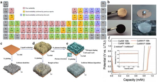
Wang et al., studied the tuning of Li wettability by reacting molten lithium with elemental additives and organic compounds containing functional groups [
50]. The negative value of Gibbs formation energy (Δ
rG) for the reaction between the molten Li and coated/doped compounds indicates the formation of a new chemical bond, which improves the Li wettability. The wettability of Li was improved by adding elements such as indium (In), tin (Sn), and magnesium (Mg), which reduces the surface tension of the material and spread the lithium. a shows the periodic table indicating the electronegativities and Li wettability strength of elements. The reaction of molten Li and the elements form a new chemical bond responsible for improving Li wettability. The coating of an organic compound containing -OH, -SO
3H, -NH
2, -NH, -PO
4, -Si-O, -F, -Cl, -Br, or -I on the surface of lithiophobic substrate is another strategy to improve the Li wettability. The successful enhancement in the lithiophilic property of porous framework, based on chemical strategy between Li and lithiophilic coating, can enable the development of ultrathin Li anodes.
Figure 3. Lithiophilic behavior on the Cu based porous framework. (
a) Electronegativities of the various elements and Δ
rG of elements/compounds reacted with the molten Li. Reproduced with permission from [
50], Springer Nature, 2019. (
b) Li wettability on the surface of Cu foil and VA-CuO-Cu substrate. Reproduced with permission from [
41], John Wiley and Sons, 2018. (
c–
e) Schematic representation of the Li plating mechanism on planar Cu, VA-CuO-Cu, and nitrogen-doped VA-CuO and Cu
2O-Cu. Reproduced with permission from [
39], John Wiley and Sons, 2019. (
f) Charge/discharge voltage profiles of the CuNW and CuNW-P collectors after 10 and 100 cycles at a current density of 2 mA cm
−2 for a total capacity of 1 mAh cm
−2 of Li. Reproduced with permission from [
47], John Wiley and Sons, 2019.
Zhang et al., reported thin lithiophilic CuO VA nanosheets grown on Cu substrate by a simple wet chemical reaction, which not only ensures the good electrical conductivity of the electrode but also facilitates the fast Li-ion transport and regulates the Li nucleation [
41]. b shows that the molten Li is uniformly spread out on the VA-CuO-Cu surface but the molten Li forms a droplet on the Cu surface confirming the lithiophilicity and lithiophobicity of the VA-CuO-Cu surface and Cu surface, respectively. To further enhance the lithiophilic property, the dual lithiophilic materials can be employed. The lithiophilic copper oxides were grown on Cu foil by liquid oxidation of bare Cu foil and the subsequent N
2 plasma treating to achieve a high CE of 99.6% for 500 cycles at 1 mA cm
−2 for 1 mAh cm
−2 capacity [
39]. The symmetrical cell demonstrated long cycling of more than 600 h with a low voltage hysteresis of 23.1 mV. This can be attributed to the regulated Li nucleation and reduced overpotential for guiding dendrite-free Li deposition. c–e clearly demonstrated that the plasma strengthened CuO/Cu
2O decorated Cu showed the uniform morphology of deposited Li. For the dense nucleation of Li and steady deposition into the porous structure, the copper nanowire with a phosphidation gradient (CuNW-P) was prepared by the chemical solution process first to grow CuNW and the subsequent chemical vapor reaction to generate phosphine gas [
47]. A high Li loaded (44%) CuNW-P demonstrated a significant decrease in the nucleation overpotential and voltage hysteresis as shown in f.
Nickel
Similar to the 3D porous Cu, the 3D porous Ni has also been considered as a better alternative to any 2D Li host. The 3D structure incorporates the active anode material and provides efficient charge transport pathways. To improve the high rate capability, cyclability, and reduce the lithium amount, the foam lithium anode was prepared by Li electrodeposition on a Ni foam substrate [
53]. Developing the honeycomb-like porous 3D Ni host on the Cu current collector via a hydrogen bubble dynamic template electrodeposition method has also been reported for stable Li and Na metal batteries [
54]. However, the electrochemical deposition of lithium into the Ni foam host material for making Li/3D Ni composite anode, generally, leads to uneven Li deposition. Moreover, the batteries have to be dissembled, cleaned, and further assembling of a new battery is needed for pairing the resultant composite electrodes with the practical cathode materials. To address this complex and costly process, the development of a simple approach for encapsulating Li inside porous Ni or other scaffolds to develop Li-based composite anode is highly looked-for.
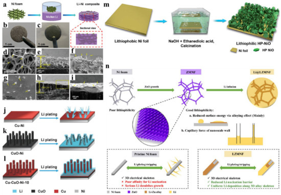
Chi et al., reported the thermal infusion strategy for pre-storing molten Li into stable 3D Ni foam to achieve a composite anode [
55]. a shows the schematic illustration of making the Li/3D Ni foam composite anode. b,c shows the digital photos of Ni foam and the Li-Ni composite. d–f shows the SEM images of Ni foam and g–i shows the corresponding SEM images after molten Li infusion. The molten lithium fills the large pores of the Ni foam and Ni frameworks protuberance marked with the yellow arrow still exist, which implies that the architecture was well preserved. The composite anode with 26 mg cm
−2 loading of Li (50 wt % of composite) exhibited improved plating/stripping cycles for more than 100 cycles at 5 mA cm
−2 in the carbonate-based electrolyte. This can be attributed to the significant reduction in the interfacial resistance and smooth Li deposition. After 100 cycles of plating/stripping, the irreversible Li plating on bare Li shows deposition of 90 μm thick Li, however, the Li-Ni composite anode does not show any thickness change. Moreover, the full cell configuration with composite anode demonstrated better rate capability, low interfacial resistance, and lower voltage overpotential compared to the bare Li anode.
To further address the issues of LMA and improve the electrochemical performance of LMBs, it is required to decorate the 3D Li host with lithiophilic coatings. The lithiophilic decoration in a porous Li host can greatly reduce the nucleation overpotential and guide the uniform Li deposition. To increase the affinity or Li wettability between the lithium and 3D porous host, various polymers [
56], organic coating [
50], elementary substances (such as Si nanoparticles [
57], plated Ag [
58]), oxides (such as NiO [
59], CoO [
60], Co
3O
4 [
61], ZnO nanoarrays (NAs) [
62]), fluorides (NiF
x) [
63], nitrides (Ni
3N) [
64], and sulfides (Ag
2S) [
65] have been utilized.
Figure 4. Lithiophilic behavior on the Ni-based porous framework. (
a–
i) Fabrication of the Li-Ni composite. Reproduced with permission from [
55], John Wiley and Sons, 2017. (
j–
l) The schematic representation of Li plating on Cu-Ni, Cuo-Ni, and Cu-CuO-Ni. Reproduced with permission from [
66], John Wiley and Sons, 2018. (
m) Schematic illustration of HP-NiO sheets’ growth on Ni foil. Reproduced with permission from [
59], Royal Society of Chemistry, 2019. (
n) The schematic illustration of lithiophilic ZnO NA modified Ni foam (ZMNF) growth and its advantages. Reproduced with permission from [
62], Royal Society of Chemistry, 2019.
Wu et al., prepared a lithiophilic Cu-Cuo-Ni hybrid structure by depositing Cu on Ni foam by radio frequency (R-F) sputtering followed by annealing at 400 °C and then finally, CuO-Ni was reduced by H
2 plasma [
66]. j–l shows the lithium plating mechanism on Cu-Ni, CuO-Ni, and Cu-CuO-Ni current collector. The copper has high overpotential for Li nucleation, which can be lowered by using the lithiophilic CuO nanowire (NW) arrays. Besides, the evenly distributed electric field on CuO-NW arrays leads to the uniform Li-ion flux and lowers the current density. The thin layer of the Cu layer on CuO still maintains the lithiophilicity, offers lower nucleation potential, and increases the electrical conductivity. The Cu film acts as a protective layer during electrochemical cycling. As a result, the hybrid Cu-CuO-Ni structure demonstrated a dendrite free Li plating with CE > 95% for more than 250 cycles at 1 mA cm
−2 and long symmetrical plating/stripping cycling up to 580 h at 0.5 mA cm
−2 with a capacity of 0.5 mAh cm
−2. Lu et al. designed nanostructured lithiophilic VA NiO hexagonal nanoplates on Ni foil (HP-NiO-Ni) by a facile hydrothermal process as shown in m [
59]. Such a HP-NiO-Ni nanostructure significantly reduces the current density and nucleation overpotential for efficient, homogeneous, and smooth Li deposition. Besides, the lithiophilic Li
2O and electronic conductive Ni formed during the reversible conversion reaction of NiO to Ni/Li
2O facilitates uniform Li-ion transport and fast electron conduction pathways, respectively. Thus, the synergy of reversible conversion reaction, and the uniform/reversible Li plating mechanism stores excess Li even at higher current density.
The formation of the Li containing alloy is believed to lower the nucleation overpotential and guide the uniform Li deposition [
1]. Sun et al. reported the lithiophilic ZnO NA modified Ni foam (ZMNF) by a facile seed-mediated hydrothermal reaction process [
62]. The ZMNF current collector improved the affinity towards the Li, provided fast Li-ion kinetics, reduced the nucleation barrier, and lessened the Li volume expansion during plating/stripping cycles. The ZnO NA improves the Li affinity with molten Li by alloying and capillary effect as shown in n. As a result, ZMNF exhibited a CE above 98% for over 300 cycles at 1 mA cm
−2 and a symmetrical cell demonstrated a long plating/stripping cycles over 1200 h at 1 mA cm
−2 to achieve 2 mAh cm
−2.
The graphene-based materials can provide scaffolds for Li electrodeposition and act as nucleation seeds. Graphitized carbon on Ni foam by heating Ni foam up to 1000 °C under Ar and H
2 and introducing methane (CH
4) [
67] or acetylene (C
2H
2) [
68], few-layered graphene sheets attached to the surface of Ni foam following the acid-catalyzed hydrothermal process [
69] have been reported for reduced overpotential and improved battery performance.
The other metal-based current collector such as titanium (Ti) and stainless steel has also been reported to guide the uniform Li deposition in LMBs. Zhang et al. proposed a porous lightweight corrosion-resistance 3D Ti current collector, which achieved outstanding CE of 99% at 1 mA cm
−2 to achieve a capacity of 5 mAh cm
−2 [
70]. The metal-based porous framework including the methods of preparation and electrochemical performance is summarized in .
Table 1. Summary of the metal-based porous framework in lithium metal batteries (LMBs).
To further enhance the lithiophilicity of Ti, the CuO nanoflower was grown on Ti mesh by the microwave-assisted solution reaction at 100 °C, which was further pressed on the Li wafer by a battery sealer with mechanical pressure of 800 psi [
71]. The Li/Cuo@Ti-mesh (LCTM) composite anode exhibited a high CE of 94.2% at 10 mA cm
−2 over 90 cycles with a low overpotential of 50 mV. The low overpotential of 50 mV and 250 mV were achieved at a high current density of 20 and 40 mA cm
−2. Lee et al., used the 3D conductive stainless steel fibrous metal felt (FMF) of a fiber diameter of 10 μm, porosity of 80%, and surface area or 0.05 m
2 g
−1 to prepare the FMF/Li electrode by roll-pressing [
72]. The FMF/Li symmetrical cell test showed a low overpotential of 30 mV at a high current density of 10 mA cm
−2.