There are two main reasons for the damage to wind turbine blades. On the one hand, the wind turbine is in a harsh external environment, and the damage faults are directly caused by external factors, such as strong wind, rain or snow, salt fog, lightning strike, freezing, sandstorm, insects, etc. The other is the invisible defects caused by process problems in the technology of man-made manufacturing. These invisible defects are subject to repeated high loads and harsh external environments during the installation and operation of the wind turbine. The gradual expansion of invisible defects can lead to damage. Due to the complexity of the blade material and structure, each damage type may be caused by a combination of causes. Different defects in the production process and different operating conditions will cause different damage types.
1. Trailing Edge Cracking
The main manufacturing materials of wind turbine blades are glass fiber-reinforced polymer (GFRP) and carbon fiber-reinforced polymer (CFRP). The two half shells of the blade, which are made of these two materials, are bonded to form a complete blade. The trailing edge of the wind turbine blade is the area where the two half shells are bonded. There are many damage modes in this area, and cracking is the main damage mode, which is mainly divided into a longitudinal crack and transverse crack. The longitudinal crack at the trailing edge refers to the crack consistent with the length direction of the blade
[12][1], as shown in
Figure 41. Such cracks mainly occur at the root and tip of the blade. The longitudinal crack at the trailing edge of the tip is mainly due to a reduction in the thickness of the shell, resulting in a reduction in the stiffness of the blade. This low stiffness leads to increased blade loading, resulting in higher shear stress on the shell and bonding material at the tip. This may be a major cause of the cracking at the tip of the trailing edge, while the longitudinal crack at the root trailing edge may be mainly due to the high stress caused by the geometric changes and fatigue load in these areas
[13,14][2][3].
Figure 41.
Longitudinal cracks found on the trailing edge of a wind turbine blade.
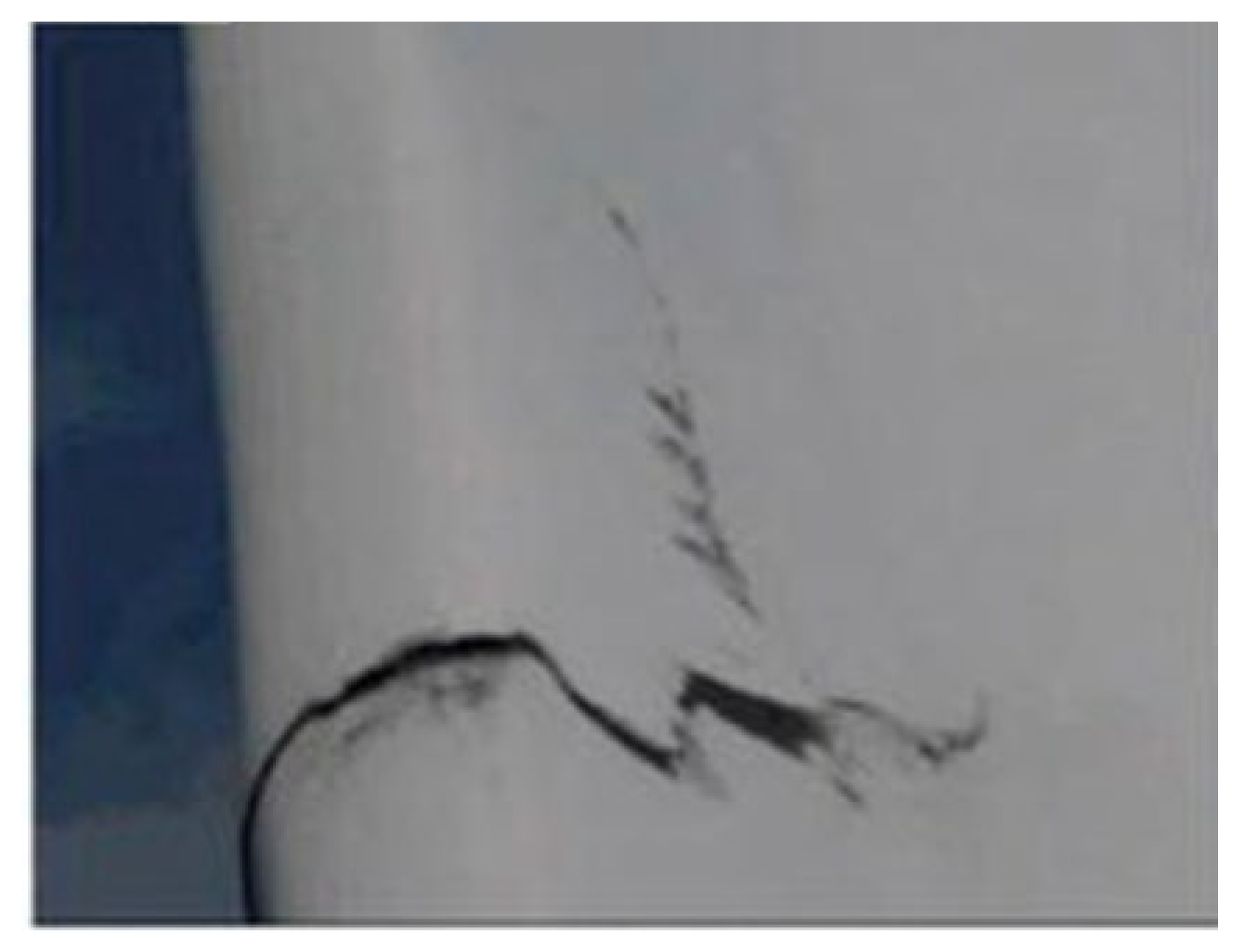
The transverse crack at the trailing edge is a crack perpendicular to the length of the blade, as shown in
Figure 52. Some of these simple transverse cracks are only on one side of the blade. It may be due to the fact that one side of the blade needs to be polished in order to eliminate the asymmetry between the two shells of the blade during the manufacturing process, which leads to a reduction in glass fiber on one side, and this kind of crack occurs under the high load or stall of the blade. There is also a transverse crack that runs through the shell of the trailing edge of the blade in two measurements. This crack may have slowly penetrated the other side of the blade from the initial side. It is also due to the high load in this area. Such a crack is relatively dangerous because it completely cuts off the high load area of the trailing edge
[15][4].
Figure 52.
Transverse cracks found on the trailing edge of a wind turbine blade.
2. Lightning Damage
Although there is already an IEC61400-24 lightning protection standard for wind turbine systems, wind turbines with lightning protection systems are still subject to lightning strikes. The damage caused by lightning to the blades depends to a great extent on the material of the blades. Studies have shown that the use of carbon fiber-reinforced polymer (CFRP) for wind turbine blades makes them highly sensitive to lightning
[16,17,18][5][6][7]. Most onshore wind farms are built on relatively remote, high ridges, which are rich in wind resources but also increase the risk of lightning strikes on wind turbines; this is because higher ridges are mostly made up of rocks or soils with high electrical resistance
[19][8]. The current lightning protection system for wind turbines uses top metal receptors to momentarily introduce strong currents underground. Soils with high resistance on ridges, on the other hand, can make it impossible for large impulse voltages to rush into the ground, which will cause blade damage. More than 88% of the lightning attachments occur within 1 m of the outermost tip, as shown in
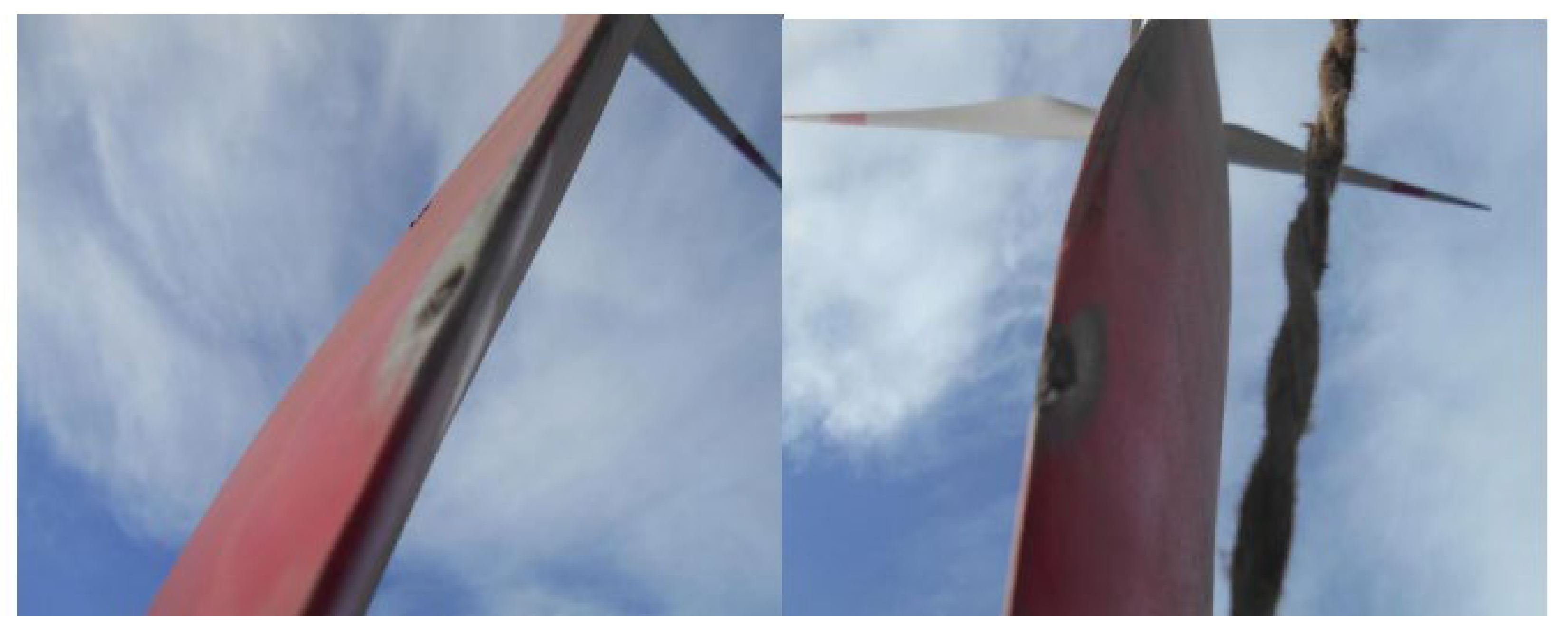
Figure 63.
Figure 63.
Holes in wind turbine blades caused by lightning strikes.
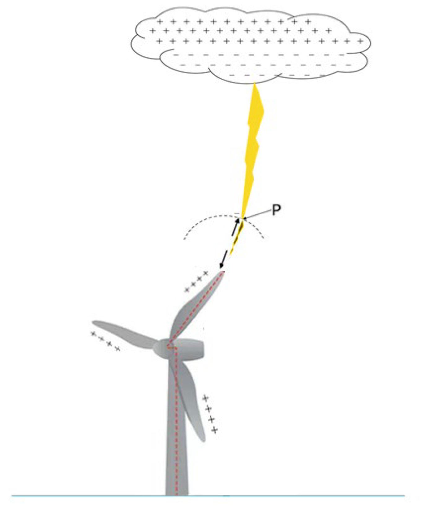
The essence of lightning is caused by the breakdown of a medium of air between a cloud and the ground or between a cloud and a cloud. The negative charge accumulated at the bottom of a thunderstorm cloud forms a strong electric field with the positive charge generated by the ground. As the charge of a thunderstorm cloud accumulates, it discharges to the ground and travels along the air
[20,21][9][10]. When the tip of the discharge reaches a certain distance from the wind turbine blade, a strong electric field is induced with the metal acceptor of the lightning protection system installed in the blade, as shown in Point P in
Figure 74. When the air at this distance reaches the breakdown threshold, the blades will also emit leads in an attempt to capture the tip of the discharge. Charge neutralization occurs in a short time and forms a circuit that forms lightning. Great thermal shock from lightning-induced arcs will cause blade damage
[22,23][11][12]. Contaminated areas on the surface of blades made of GFRP composite materials (e.g., humidity, dirt, salt, insects, etc.) can also become receptors under a sufficient electric field
[19,23][8][12].
Figure 74.
Lead development process diagram for when lightning strikes wind turbine blades.
3. Corrosion Contamination at Leading Edge
Corrosion and contamination at the leading edge of wind turbine blades is one of the key problems in wind power production, as shown in
Figure 85. Erosion and contamination at the leading edge of the blade results in an increase in the resistance coefficient and a corresponding decrease in lift coefficient, which reduce the generation of electricity. Studies have shown that corrosion contamination on the leading edge of blades can reduce the annual energy production (AEP) by 2% to 3.7%
[24][13]. Severely eroded blades result in AEP up to 25%
[25][14]. The AEP of heavily contaminated blades is reduced by 10–13%
[26][15]. Noise is also generated. The degree of corrosion and contamination of wind turbine blades depends on environmental conditions such as temperature, humidity, pollutants in the atmosphere, and wind speed. Studies have shown that blade erosion and contamination results in the most significant losses at lower wind speeds, while little or no power loss is achieved at higher wind speeds than the rated ones
[27][16].
Figure 85.
Corrosion pollution of a wind turbine blade’s leading edge.
Front edge corrosion contamination is a complex process. The main reason is that raindrops, hail, sand particles, etc., repeatedly hit the leading edge of blades, together with environmental conditions such as insects, dust, salt (corrosion of salt mist of offshore blower), and so on. Large droplets of rain hit the leading edge of the blade and generate pressure waves on the surface. These pressure waves propagate in the material of the blade and begin to cause fatigue, cracking, and surface roughening of the blade surface. As the density of the pit increases, a groove will eventually form
[28,29][17][18]. Other large and hard particulates, such as hail and gravel, have high kinetic energy when impacting the leading edge of the blade. Especially in areas close to the tip of the blade where the speed is very fast, the erosion of the blade surface is a direct result. In severe cases, delamination and cracking will occur, which will reduce the structural stability of the blades. Blade contamination caused by insects occurs mainly in areas with low humidity and wind speed and temperatures of 10 degrees Celsius or higher because these are favorable conditions for insect survival
[27][16]. Additionally, chemicals such as salts and acids in rain or sea air will accelerate the corrosion of the blades, because they can interact chemically with the coating material
[28,30][17][19].
4. Icing
The icing of wind turbine blades is also an issue of great concern. Because wind turbine blades are very precise aerodynamic components, even slight icing can cause slight changes in blade shape, which increases the friction coefficient and creates turbulence; ultimately, the aerodynamic performance of the blades is affected, resulting in an impact on power generation, A research project analyzed 517 wind turbines that produced 682 MW and discovered that in 29 months there was a loss of 18,966 MWh of the total produced power because of turbine blades icing
[31,32][20][21]. Because ice can increase the drag coefficient of the blades, the noise generated by the blades is also higher than normal operating levels. Icing causes an imbalance in the mass of each blade and leads to irregular vibration. When this irregular vibration exceeds a certain threshold value, the blades will fatigue and break. Because the blades themselves become brittle in cold weather, this irregular vibration increases the risk of blade breakage. In addition, if the frozen blades are still running, the broken blades will be thrown out at a high speed, which brings great safety hazards to nearby residents and facilities. So, it is very important to detect ice and start de-icing on time.
The icing on wind turbine blades depends on temperature, humidity, air density, wind speed, and other variables. Ice characteristics are influenced by different parameters in ISO 12494, 2001
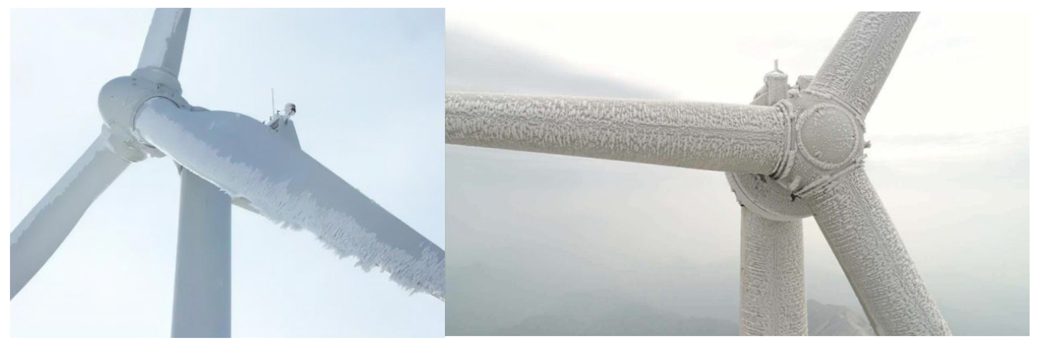
[33][22]. Different environments produce different ice types. The most common type of icing on wind turbine blades is frost, which is dense and very brittle. Because of the velocity of the incident. This ice first appears at the leading edge of the blade and then gradually covers the rest of the blade, as shown in
Figure 96. Twenty percent of wind farms are located at high altitudes, where populations are scarce but there are abundant wind resources
[34][23]; however, these areas have very strong wind and high cold air density, which poses a great challenge to the anti-icing and de-icing of wind turbine blades
[35][24].
Figure 96.
Ice on wind turbine blades.
5. Delamination
The manufacturing materials of wind turbine blades are composite materials. In the composite material, the bonding may not be good or there could be areas without bonding, which are prone to delamination defects. Under these operating conditions, the wind turbine blade will bear a high aerodynamic load, which will make the blade bend. Delamination may reduce the critical buckling load of the blade and reduce the overall stiffness and strength of the blade
[36][25]. Delamination triggers different buckling modes. If the delamination is near the outer or inner surface of the blade, it may cause local buckling; if the delamination is near the center of the blade laminate, it will cause overall buckling, as shown in
Figure 107. Buckling will reduce the strength of the blade, which poses varying degrees of danger to the structure. However, when the combined effect of local buckling and delamination reaches a certain degree, the blade will suddenly break
[37,38][26][27].
Figure 107.
Local and global buckling modes for layering.
The delamination defect of the blade is usually caused by limitations during the manufacturing process, areas with a high stress concentration (such as hole and notch) around the discontinuous part of the structure, and/or impact damage during the process of production, transportation, and maintenance, etc. In order to avoid large delamination defects of wind turbine blades, the quality control of the blades is usually carried out through visual inspection or ultrasonic scanning after production.
6. Other Defects
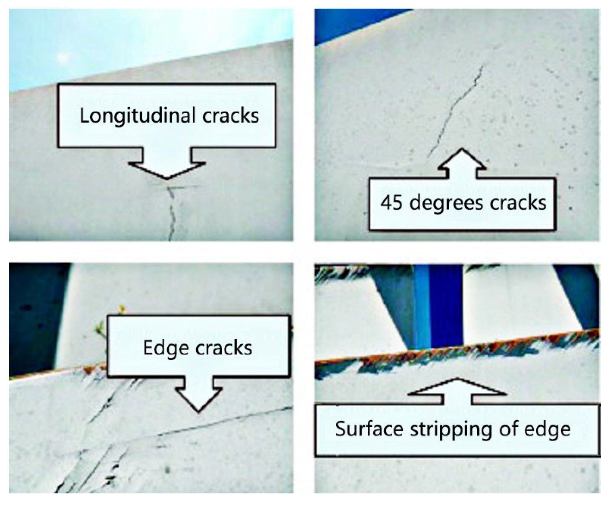
With the increasing service time of wind turbines, the surface of wind turbine blades will gradually show slight cracks. These cracks usually expand with the service time of the wind turbine and the load of the wind turbine. If it is serious, it will lead to the fracture of the blade. Generally, a strong wind will make the blade bear complex and changeable high-strength loads, resulting in cracks and damage from the root, surface, and trailing edge of the blade, as shown in Figure 118. Therefore, the complex and changeable load is a direct factor affecting the service life of wind turbines.
Figure 118.
Different types of cracks.

