Your browser does not fully support modern features. Please upgrade for a smoother experience.
Please note this is a comparison between Version 1 by Jose Luiz de Medeiros and Version 2 by Sirius Huang.
Gas–liquid membrane contactor (GLMC) is a promising process intensification technology for offshore natural gas conditioning in which weight and footprint constraints impose severe limitations. Thanks to its potential for substituting conventional packed/trayed columns for acid-gas absorption and acid-gas solvent regeneration, gas-liquid membrane contactors have been investigated experimentally and theoretically, wherein aqueous-amine solvents and their blends are the most employed solvents for carbon dioxide removal from natural gas in gas-liquid membrane contactors.
- gas–liquid membrane contactor
- natural gas conditioning
- carbon capture
1. Introduction
The global population is continuously increasing, and it is foreseen that it will exceed 10 billion by 2050 [1]. In this scenario, natural gas (NG) exploration and production attract interest in meeting the growing world energy demand [2]. Moreover, NG plays a key role in the transition to renewable energy sources [3] as NG is the cleanest fossil fuel due to its high hydrogen/carbon ratio [4].
Proven NG reserves around the world are approximately 196.9 trillion cubic meters [4], but onshore NG reserves—with simpler production that is closer to consumers—are decreasing, while offshore NG reserves far from the coast and in deep waters are growing [5]. In this regard, oil production with associated NG in deep-waters and ultra-deep-waters usually presents high carbon dioxide (CO2) content and gas-to-oil ratio, which entail difficulties for gas processing in offshore rigs where there are weight/footprint limitations [6]. Due to complex logistics for NG production/transportation in the context of deep-water offshore rigs, high costs lead to significant offshore CO2-rich NG reserves being left unexplored. Albeit the existence of efficient technologies for onshore NG production, innovative low-cost technologies are necessary for deep-waters processing of CO2-rich NG [5].
The concept of carbon capture utilization and storage (CCUS) is necessary to allow a smooth transition from fossil energy to renewable energy to keep a profitable industrial operation. In CO2-rich NG processing, CO2 removed from NG is transported to a storage site [7]. Promising CO2 utilizations are enhanced oil recovery (EOR) in oil-and-gas reservoirs [8] or enhanced gas recovery (EGR) in gas reservoirs [9]. In CCUS-EOR or CCUS-EGR, CO2 is injected into reservoirs to increase oil and gas production. If the increase is high enough, the extra revenues can offset CO2 capture/transportation costs entailing profits [7].
1.1. Natural Gas Purification Requirements
Raw NG primarily contains methane (CH4) and secondarily ethane, propane, butanes, and heavier hydrocarbons. Other common constituents are CO2, hydrogen sulfide (H2S), water (H2O), nitrogen (N2), and trace components. Raw NG purification is necessary to meet gas pipeline specifications and market/environment regulations [10].
NG processing usually comprises: (i) H2S removal [11]; (ii) water dew-point adjustment (WDPA) via dehydration [12]; (iii) hydrocarbon dew-point adjustment (HCDPA) [10]; and (iv) CO2 removal. H2S causes pipeline/equipment corrosion, it is undesirable in combustion, and threatens human health and the environment [11]. WDPA is necessary mainly because water condensed from NG may form solid gas-hydrates under high-pressure and low-temperature typically found in subsea pipelines [12]. HCDPA is necessary to avoid hydrocarbon condensation in pipelines (safety and efficiency issues) and to recover valuable NG liquids [13]. Besides, HCDPA removes hydrocarbons to meet the heating value specification (Wobbe Indexes), ensuring adequate gas–turbine and combustion equipment operations minimizing emissions [5]. Finally, CO2 content is reduced to 2–3 mol%, increasing NG heating value, preventing solid CO2-hydrates, avoiding corrosion, and avoiding occupying pipeline capacity with inert [14].
1.2. Carbon Capture from CO
2
-Rich NG
Several technologies exist for carbon capture from CO2-rich NG. Pressure-swing adsorption (PSA) prescribes selective CO2 adsorption onto solid adsorbents at high-pressure conjugated with low-pressure CO2 desorption [15]. PSA issues comprehend the methane purity-recovery tradeoff [16] and the low-pressure CO2 release entailing compression costs [17].
Cryogenic distillation is considered for CO2 ≥ 10 mol% due to lesser energy consumption and footprint compared to chemical absorption [18]. However, since cryogenic distillation operates at temperatures below the CO2 triple-point [19], there is a risk of CO2 freeze-out (dry-ice) inside the equipment, causing blockage [18]. Moreover, high-pressure cryogenic columns are protected against pressure surges by blowdown valves, which under cryogenic conditions can lead to dry-ice formation via the Joule–Thomson effect [20].
In offshore CO2-rich NG processing, membrane permeation (MP) is adopted due to its low footprint, modularity, and flexibility to feed composition changes [21] and is recommended for high CO2 content NG [22]. However, thanks to its capacity-selectivity tradeoff [23], permeate methane losses are remarkable, and the low-pressure CO2-rich permeate imposes high compression costs [24].
Physical absorption (PhA) prescribes a physical solvent that dissolves CO2 at high-pressure [25], requiring high CO2 fugacity for high CO2 loadings [26]. PhA is much less energy-intense for solvent regeneration compared to chemical absorption at the expense of a low-pressure CO2 stripping [6]. PhA drawbacks comprise (i) low CO2/CH4 selectivity entailing CH4 losses in the stripped gas; (ii) low-pressure stripped gas entailing compression costs for EOR destination.
The most mature technology for CO2 and H2S removal from CO2-rich NG is chemical absorption (ChA), which is based on CO2 reactions with aqueous-alkanolamine solvents [27]. Aqueous-monoethanolamine (aqueous-MEA) and aqueous-methyl-diethanolamine (aqueous-MDEA) are the most used chemical solvents [28]. The main advantage is the high CO2/CH4 selectivity in a wide range of operation pressures [27] and this selectivity is particularly high at low CO2 fugacity [22]. ChA generally operates with packing columns that have beds of variously-shaped packings—e.g., Pall rings or Berl saddles—providing a high specific surface area for CO2 transfer. Packing columns are fed with lean solvent at the top and with raw NG at the bottom in countercurrent flows [29]. ChA drawbacks comprise: (i) high heat-ratio (kJ/kgCO2) solvent regeneration [28]; (ii) solvent degradation (oxidation and thermal degradation) causing corrosion and efficiency loss; (iii) low-pressure CO2 stripping entailing compression costs for EOR; (iv) hydraulic issues (e.g., foaming, channeling, flooding and entrainment) [29].
The gas-liquid membrane contactor (GLMC) combines MP and ChA advantages—without the respective drawbacks—becoming a promising solution for CO2-rich NG decarbonation [30]. In GLMC, the hollow-fiber membrane (HFM) provides a non-dispersive gas-liquid contact avoiding packing-columns hydraulic problems like foaming, channeling, flooding, and entrainment [31]. Comparatively, with MP, the selective chemical solvent and thousands of HFM inside the GLMC shell ensure high CO2/CH4 selectivity with low CH4 loss, high mass transfer area per shell, compactness, modularity, and easy scale-up, all desired attributes for CO2 removal from CO2-rich NG with aqueous-amine solvents in offshore rigs [22]. Comparatively, with conventional CO2 absorption packing columns, GLMC reaches reductions up to 70% and 66% in size and weight, respectively [32]. Angular indifference is another advantage of GLMC vis-à-vis the sway of floating offshore rigs [33].
2. GLMC: Principles, Materials, and Configurations
GLMC is modular equipment configured in batteries. Each GLMC module contains thousands of hydrophobic HFM tubes fixed into a shell-and-tube arrangement [34][51] in Figure 1. Equipment inclination translates into GLMC angular indifference [33].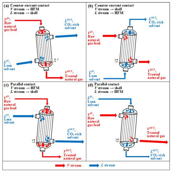
Figure 1. GLMC setups: Counter–current contact: (a) HFM:V, Shell:L; (b) HFM:L, Shell:V. Parallel contact: (c) HFM:V, Shell:L; (d) HFM:L, Shell:V.
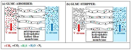
Figure 2.
Multicomponent mass transfers: GLMC-absorber (
a
); GLMC-stripper (
b
) (H
2
O can move
V→L
or
L→V)
.
2.1. HFM for GLMC
Contrarily to MP, which uses dense selective membranes, GLMC adopts non-selective microporous HFM to allow V-L contact and selectivity is imposed by the solvent [45][61]. Figure 3 depicts how HFM works as a mass transfer barrier preventing phase dispersion [46][62]. Figure 3a represents direct V-L contact in tray columns or packing columns with phase dispersion. Figure 3b shows microporous HFM with gas-filled pores ensuring V-L contact with low mass transfer resistance [47][63]. However, during GLMC operation, the solvent may fill the pores (Figure 3c), increasing mass transfer resistance drastically and reducing transfer fluxes. This undesirable phenomenon compromises GLMC performance and is called membrane pore wetting (MPW) [46][62]. MPW is influenced by membrane characteristics (pores diameter, tortuosity, porosity, surface roughness), solvent surface tension, and operating conditions, while some solvents may favor MPW by affecting HFM hydrophobicity, morphology, and roughness. To avoid MPW, HFM material must be hydrophobic such as polypropylene (PP), polyvinylidene fluoride (PVDF), polytetrafluorethylene (PTFE), polyether ether ketone (PEEK), and solvents should have high surface tension, negligible vapor pressure and should not chemically attack HFM [48][41]. Figure 3d shows another solution against MPW wherein dense HFM CO2 permeable and solvent impermeable are used. However, dense HFM presents high transfer resistance and does not fit in the original GLMC concept of non-dispersive V-L contact [46][62]. A compromise solution uses composite HFM (Figure 3e) consisting of an ultrathin dense skin layer onto microporous support. The ultrathin layer is generally a fluorine-based hydrophobic material, while the microporous support—made of a cheaper material like PP—should be mechanically resistant, chemically stable, and highly porous to minimize transfer resistance [46][62].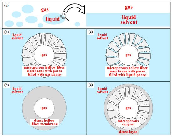
Figure 3. HFM as a barrier for mass transfer without phase dispersion: (a) direct V-L contact with phase dispersion; (b) microporous HFM V-L contact with gas-filled pores; (c) microporous HFM V-L contact with liquid-filled pores; (d) Dense HFM without V-L contact; (e) Composite HFM without V-L contact.
2.2. Solvents for GLMC CO
2
Absorption
Hereafter, physical and chemical GLMC solvents are discussed.2.2.1. Physical Solvents
PhA relies on CO2 solubility, which follows Henry’s law, such that the absorption loading is favored by high CO2 fugacity and low temperature. Thus, PhA can perform CO2 removal from high-pressure raw NG. Comparatively to ChA, the main PhA advantage is the lower heat ratio for solvent regeneration [49][64]. Physical solvents are listed in Table 14 for GLMC CO2 removal from NG.Table 14.
Physical solvents proposed for GLMC CO
2
removal from NG.
2.2.2. Chemical Solvents
ChA is characterized by high CO2/CH4 selectivity and limited absorption loadings (kgCO2/kgSolvent), both due to chemical reactions of the solvent with CO2. Aqueous-amine solvents are the most used in ChA for CO2 capture from NG due to high reactivity, low cost, easy regeneration and high CO2/CH4 selectivity [56][71]. Aqueous-MEA, aqueous-DEA (aqueous-diethanolamine) and aqueous-MDEA are examples of aqueous-amine solvents extensively employed for NG decarbonation since 1930 [57][72]. However, aqueous-amines exhibit drawbacks such as high heat-ratio (kJ/kgCO2) solvent regeneration, thermal/oxidative degradation, corrosiveness and limited CO2 loading [58][73]. Aqueous-MEA is the most used for ChA CO2 capture, exhibiting high reactivity at low-pressure or high-pressure [59][74], while aqueous-MDEA is adequate at high pressure despite lower absorption rate [60][75], which recommends using reactivity promoters. Table 25 lists literature studies on chemical solvents for GLMC NG decarbonation.Table 25.
Chemical solvents investigated for GLMC CO
2
removal from NG.
| Chemical Solvents | Reference |
|---|---|
| Primary amines | |
| Aqueous-MEA | [61][76] |
| Aqueous-DGA (Aqueous-Diglycolamine) | [62][77] |
| Secondary amines | |
| Aqueous-DEA | [63][78] |
| Aqueous-DIPA (Aqueous-Diisopropanolamine) | [64][79] |
| Aqueous-PZ (Aqueous-Piperazine) | [65][80] |
| Aqueous-EMEA (Aqueous-N-ethyl-monoethanolamine) | [66][81] |
| Tertiary amines | |
| Aqueous-TEA (Aqueous-Triethanolamine) | [65][80] |
| Aqueous-MDEA | [67][82] |
| Sterically hindered amines | |
| Aqueous-AMP (Aqueous-2-amino-2-methyl-1-propanol) | [68][83] |
| Alkali-salts | |
| Aqueous-K2CO3 | [69][84] |
| Alkali | |
| Aqueous-NaOH | [70][85] |
| Amino-acid salts | |
| Aqueous-AAS | [71][86] |