Your browser does not fully support modern features. Please upgrade for a smoother experience.
Please note this is a comparison between Version 1 by Khem Gautam and Version 2 by Conner Chen.
Thermo-mechanical energy storage can be a cost-effective solution to provide flexibility and balance highly renewable energy systems. Thermo-Mechanical Energy Storage (TMES) can be directly compared with pumped hydro storage because they have similar discharge characteristics and capacity (order of 100 s of MW).
- energy storage
- thermo-mechanical
- market analysis
1. Thermal Energy Storage (TES)
Thermal energy can be stored in the form of sensible, latent, and thermo-chemical heat. Although the concept of using latent heat for temperatures above 500 °C is discussed in the literature [1][2][13,14], these kinds of technologies are in the conceptual phase. Thermo-chemical heat storage technologies are not developed enough for the high-temperature thermal storage required for storing heat to produce electricity [3][15]. Sensible heat storage is the simplest and only mature technology to store heat at the high temperatures required for bulk electricity storage.
Sensible heat storage systems store heat by increasing the single-phase storage medium’s temperature. The stored high-temperature heat is converted to electricity by using different cycles such as the Rankine, Brayton, and Air-Brayton cycles. The overall efficiency of the discharge cycle can be improved by the co-generation of heat.
Molten salts, oil, ceramics, and rocks are used as the typical storage medium, but other storage materials can be used as well [4][16] for using desert sand as high-temperature thermal storage material. Figure 12 shows a general outline of the high-temperature sensible heat storage system. The charging configuration may be different depending on the charging method.
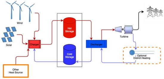
Figure 12. Generic schematic of a two-tank high-temperature heat storage system used for molten salt. In variations with one tank, the hot and cold storage are separated naturally by the temperature gradients.
1.1. Liquid-Molten Salt-Based Systems
Molten salts have unique thermo-physical properties that make them an ideal storage medium. They have a high boiling point, low vapor pressure, low viscosity, and high specific heat capacity. By changing the chemical composition of salts, the thermophysical properties of the salt can be adjusted.
Two distinct configurations for molten salt storage exist. The two-tank system uses molten salts as heat transfer fluid and storage medium by storing cold and hot salts in two separate tanks. The thermocline system uses a single storage tank where hot and cold salt is separated naturally by a temperature gradient. The dual tank configuration (about 30% more costly than the single tank) is exclusively used for modern large-scale CSP plants with a power rating above 10 MW because they can constantly supply high-temperature heat and have lower storage loss compared to single-tank systems [5][17].
During charging, electric power is converted into heat using electrical heaters. If high-grade heat is available, such as from a concentrated solar, gas burner, or nuclear reactor, the high-grade is used directly to charge the system. The heat from the molten salt storage is used to discharge energy, typically in steam-based Rankine cycles.
The use of molten salts dates back to 1960, when they were used as thermally stable fuel to develop a new generation of nuclear reactors [6][18]. The first use of molten salt as a heat storage medium started only in the early 1990s as a heat storage medium for a CSP plant on the Mojave desert in California [7][19]. The success of the 10 MW pilot power plant on the Mojave desert helped the commercial development of molten salts as a storage medium for CSP, making it the most widespread storage material in CSP applications today.
More than 95% of global thermal energy storage operation in CSP plants is based on molten salt technology. It is estimated to have a total storage capacity of 21 GWh at the end of 2019 [8][9][20,21]. Molten salt storage is a matured technology for CSP application marketed by several multi-national companies, including MOSAS from MAN, eTES from Flagsol, Pintailpower, Yara international, Aalborg CSP, and Alpha Laval.
The standard CSP technology uses solar towers to heat the molten salt and store the hot salt in pressurized flat bottom tanks at a temperature of 565 °C. Cold storage is maintained at a temperature of 270 °C. The discharge cycle uses the layout of a typical steam-based power plant. For example, the Gemasolar plant in Spain, built-in 2011, uses three pressure level steam turbines to generate 20 MW of power. Ouarzazate Solar Power Station in Morocco is the largest CSP plant globally, with a power capacity of 510 MW [10][22]. The DEWA project in Dubai, expected to be completed in a few years, will dethrone the Ouarzazate for the title of the largest CSP plant with a power capacity of 700 MW [11][23].
Although molten salt storage is mainly associated with CSP, it can be used in areas with abundant wind resources by replacing solar fields and towers with electrical heaters. In a typical CSP application, the investment cost and space required for installing a solar field are substantial; in comparison, electric heaters are significantly cheaper. Electric heaters provide greater flexibility of using excess electricity by scaling up the charging power and storing a relatively large amount of energy in a short duration. However, the Rankine-based discharge cycle is relatively costly.
1.2. Solid-Rocks-Based Systems
Rocks are thermally and chemically stable in a wide temperature range. They are non-toxic and non-flammable, and they have good thermal properties: high specific heat, good thermal conductivity, low thermal expansion coefficient, and high mechanical resistance to thermal cycling. Some types of rocks can efficiently be heated up to 1000 °C and transfer heat effectively with air. These properties make solid rocks an excellent storage medium for high-temperature energy storage. It is worth mentioning that concrete also offers low cost, stable thermal properties, and simple industrial production. The use of concrete for temperatures <400 °C is well-documented [12][13][14][24,25,26]. The use of concrete for temperatures >500 °C, generally required for good thermal-electrical efficiencies, is not commercially developed yet.
During charging, electric power is converted into heat either using electrical heaters or a heat pump. Air is used as the heat transfer fluid to transfer heat to the rock bed, recover heat, and produce steam in a heat recovery steam generator that discharges the system and produces electricity and possibly heat for district heating.
Zurich Utility built the first known high-temperature rock bed storage in Switzerland in 1984. This 5 MW solar plant was used as a reference system to study the potential of such systems theoretically and experimentally in 1991 [15][27]. At that time, the pressure drop across the rock bed was a serious problem. Many theoretical and demonstration studies [16][17][18][19][20][28,29,30,31,32] contributed vastly to understanding and designing effective rock storage for commercialization of the technology.
Siemens Gamesa started model development of electric thermal energy storage with rocks in 2002. In 2004, the first test site with 5 MWh capacity was built. Under the support of the Federal German Ministry of Economic Affairs and Energy, a real-scale pilot demonstration plant was commissioned in 2019. The pilot plant located in Hamburg, Germany, uses over 1000 tons of rock and has a thermal storage capacity of 130 MWh. Based on these demonstrations and research projects, Siemens Gamesa has commercialized the technology as scalable and modular units at different capacities.
In Denmark, the HT-TES (High-Temperature Thermal Energy Storage) demonstration project (2016–2019) analyzed the potential of using various types of rocks under cyclic thermal loading. The project found that the rock storage is technically sound and has socio-economical feasibility in the long term. The project also concluded that the current tariff structure might not support the corporate feasibility of rock storage.
At the point of writing, only a few rock-based TES demonstration plants operate at a scale > 1 MW, and temperatures higher than 500 °C. Siemens Gemesa’s Electric Thermal Energy Storage demonstration plant in Germany has a rated discharge power of 1.5 MW and uses 1000 tons of volcanic rocks to store 130 MWh of electric energy. The plant has a charging efficiency of 99%, discharge efficiency of 45%, and storage losses of <1% of the stored energy per day.
1.3. Energy Efficiency and Losses
Molten salt-based TESs that use the electric heater for charging achieve a charging efficiency close to 99%. Small rock sizes and effective flow rates are required for a comparable charging efficiency [21][33] in rock-based systems.
The discharge efficiency depends on the design of the discharge system and the temperature of the storage. Typical sensible storage uses the Rankine cycle for discharge. Overall, the round-trip efficiency of the best-known Rankine cycle-based system for power generation working with the highest temperature of 565 °C, is around 40% [22][23][34,35].
If sensible heat is stored at a temperatures higher than 600 °C, supercritical steam generators can be used, and such systems’ practical round-trip efficiency can be around 45%. Research on discharge cycle based on supercritical CO2 Brayton cycle at temperatures higher than 600 °C is ongoing, and it is expected to increase efficiency and reduce the cost of TES even further [24][25][36,37].
The storage tank’s temperatures, size, and height/diameter factor and insulation influence the heat losses during storage. Annual storage losses in a commercial CSP plant with typical steel tanks with standard insulation were observed to be <1% per day [7][19]. For rock-based systems, the storage losses themselves are low, and studies on continuous 8 h-charging/16 h-discharging cycles have shown that the storage losses are about 0.5% of the input heat [18][30]. It is safe to assume storage losses to be <1% day for rock storage systems that do not operate continuously.
1.4. Typical Characteristics and Capacities
TESs can be constructed as scalable modular units. Enhancing the storage capacity does not require extra investment for the power components. The charging component typically costs <10% of the discharge component; therefore, the total investment costs for additional storage and charging capacity are relatively small. This enables TESs to charge systems quickly and dispatch electricity for a longer duration.
An an energy to power ratio (ratio between storage capacity and discharge power) of 7 to 15 is typically used for CSP applications. A storage duration longer than a few weeks is limited by the energy loss in the storage tanks. Although typical storage losses for molten salt systems are <1% per day, a part of the tank may be exposed to higher losses that promote solidification of the salt [26][38]. Storage duration >7 day should only be considered if solidification is entirely ruled out, for example, by having auxiliary electric heaters in many different parts of the tank. For rock-based systems, a storage duration of a few weeks is possible.
1.5. Research and Development Perspective
The high melting point of the molten salt mixture means that additional energy is needed to avoid the solidification of salts. A hot storage temperature of at least 600 °C is needed to utilize more efficient supercritical steam or supercritical CO2 generators. Some promising research results for finding a new generation of molten salts are reported by [27][28][29][39,40,41]. Molten salt is an electrolyte, which, at high temperatures, is corrosive. Large-scale storage depends on the ability to use low-cost construction materials. Despite much research in the area [30][31][32][42,43,44], finding appropriate low-cost storage tank material and coating to prevent corrosion is still a challenge.
When rocks are heated to temperatures of 600 °C from the ambient, they expand (1% to 2%) and subsequently contract when cooled [33][45]. The thermal expansion of steel is twice the thermal expansion of rocks. It is still a challenge to solve expansion stress in the steel tanks cost-effectively. Even when they are of the same type, rocks may have different individual minerals in them. Different expansion coefficients of the individual minerals may cause internal fractures and disintegration in the form of dust. The dust wears the turbomachinery. An effective solution for dust management is yet to be found.
2. Pumped Thermal Energy Storage
PTES uses electrical energy to power a heat pump cycle during charging to create a temperature difference between two heat reservoirs. The thermal storage can be sensible, latent, or chemical. During discharging, the temperature difference between the reservoirs drives a thermal cycle. The Carnot efficiency does not limit the round-trip efficiency of PTES because it is theoretically possible to extract most of the charging work during discharge.
Bryton cycle-based PTES systems use an ideal gas as the power cycle working fluid and operate similar to reversible Joule–Brayton cycles. Rankine cycle-based systems use transcritical working fluids (often CO2) or the subcritical (or latent) PTES with steam or ammonia as the working fluid.
Patents with the concept of PTES were already filled in the 1920s [34][10]. There is a wide range of theoretical studies conducted on PTES based on Bryton cycles [35][36][37][46,47,48], Ericsson cycles [38][49], Rankine cycles based on CO2 [39][40][41][50,51,52], and steam cycles [42][53]. Practical implementation of the concept other than PTESs based on Bryton cycles is limited; therefore, thwe subsequent text focus on Bryton cycle-based systems in the subsequent text.
An Italian company, Saipem, filed a patent application [43][54] for a PTES based on Bryton cycles that use argon as the working fluid and sensible hot storage at temperatures above 1000 °C using concrete in 2007. At the same time, a UK-based company, Isentropic Ltd, filed another patent [44][55] that also used argon as the working fluid but stored heat at temperatures around 600 °C using a Packed bed. These two systems were extensively discussed in the literature [35][45][46][47][46,56,57,58]); however, it appears that the concept never got materialized. Isentropic Ltd is bankrupt, and there are no current records that show Saipam’s technology was ever built. A Google spin-off, Malta Inc, is currently working with a PTES design based on Bryton cycles [48][59] that utilize molten salt for hot storage and a chilled liquid to store cold [48][59].
In 2021, Stiesdal storage technologies and the energy and fiber-optic group Andel signed an agreement to build a utility-scale prototype of a new full-scale rock storage system based on the innovation of Stiesdal storage technologies [49][50][51][60,61,62]) for long-term energy storage. A demonstration plant of 2 MW discharge power capacity is being constructed for commissioning in 2022. Stiesdal’s Grid-Scale Technology uses air as the working fluid and rocks as a storage medium. During charging, air from the low-pressure cold tank (at 2.5 bar) is compressed to a pressure of 7.5 bar resulting in an exit temperature from the compressors of about 540 °C (1–2 in Figure 23).
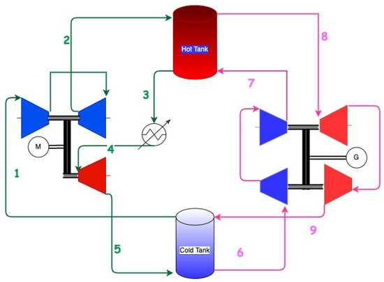
Figure 23. Schematics of Stiesdal’s Grid Scale technology. Green is the charge cycle; pink is the discharge cycle. The compressors are blue, and the turbines are red. The schematic is verified with Stiesdal storage technologies.
The heat of compressed air is transferred in the high-pressure hot storage tank (2–3) with the volcanic rocks. The air exiting the high-pressure tank is cooled to the ambient (3–4) and further expanded in a turbine (4–5) to lower the temperature and pressure. Cold air at a temperature of about −39 °C is used to transfer the heat in the low-pressure cold storage tank (5–1).
During discharge, the low-pressure cold air from the cold store is compressed (6–7), heated in the high-pressure tank to temperatures of about 535 °C (7–8), and expanded in turbines (8–9) to release energy. The temperature exiting the turbines at about 320 °C finally enters the low-pressure tank. A simplified schematic is shown in Figure 23.
2.1. Energy Efficiency and Losses
Isentropic efficiency of turbomachinery, work ratio, and heat-to-work ratio are three main parameters that dictate the overall round-trip efficiency of PTES.
The work ratio, i.e., the ratio between the compression and expansion work during charging, can be increased by increasing the pressure ratio or increasing the ratio between discharged temperature after the compressor (T2 in Figure 23) and the inlet temperature to the compressor (T1 in Figure 23) in the charging loop. Ratio (T2/T1) depends on the working fluid; for example, argon achieves a higher value of (T2/T1) than air while operating with the same pressure ratio and same sets of turbomachinery. The pressure ratio, and thus, the work ratio for a given working fluid, cannot be increased infinitely because of the difficulty in storing thermal energy at high pressure. For systems operating with low work ratios (also implies low storage temperatures), a slight decrease in the isentropic efficiency of turbomachinery has a large impact on overall round-trip efficiency. The heat-to-work ratio is the amount of heat possessed by the system for a given amount of net-work input. Large heat-to-work ratios are undesirable because heat transfer irreversibilities have a large impact on the cycle performance.
Rankine cycle-based PTES systems use sub-critical or transcritical cycles, so they have a high work ratio, but the heat-to-work ratio of such systems is also higher. In systems with a high heat-to-work ratio, the heat exchanger designs become the critical factor limiting round-trip efficiency.
Since PTES systems store energy as the temperature difference between the heat reservoirs, the heat-to-work ratio is also the charging efficiency of the system. Patented and demonstrated PTES systems have a heat-to-work ratio between 2 and 3. The discharge efficiency mainly depends on the discharge cycle and the pressure ratio, and it is between 0.2 and 0.25 for Bryton cycle-based PTESs.
Thermal and pressure losses further contribute to the decrease in round-trip efficiency. Thermodynamic analysis of patented PTES technologies showed that they could achieve theoretical maximum round-trip efficiencies between 59% and 70% [35][52][46,63]. In a more realistic cyclic transient simulation of a similar PTES system, ref. [53][64] found that an efficiency of 56.9% might be achievable under realistic operating conditions when all loss components and cyclic operations are considered. Scalable PTES systems that might achieve round-trip efficiency of more than 55% require significant development.
2.2. Typical Characteristics and Capacities
PTES systems can also be constructed as scalable modular units. Unlike TES, the highest storage temperature is not the only critical factor for PTES. Therefore, a wide range of thermal storage mediums (chemical, latent, sensible) can be employed at various temperature levels. The typical storage period of PTESs is similar to other Thermo-Mechanical Energy Storages (TMESs) ESs and can cover hours to weeks. The storage losses are mostly related to the thermal losses in the storage medium.
Since the energy input-to-output ratio depends on the round-trip efficiencies, a charging system will have a larger rated capacity than the discharge system. The typical cost of charging components of 1 MW rating is less than that of the discharge components of the same rating (cost of compressors is less than half that of the turbines [54][65]). For a discharge system with a rated discharge capacity of 1 MW and 50% round-trip efficiency, a charging system of 2 MW is required, resulting in a high cost for the charging system.
2.3. Research and Development Perspective
The main technical challenge of using PTESs today is that the compressors required to compress air to high temperatures are not readily available. State-of-the-art high-pressure aero gas compressors operate at a temperature range of 450 °C to 700 °C [45][56]. These titanium compressors are costly, and even they do not meet the requirement for temperatures above 700 °C. There is a need to find a technical solution, so the existing gas turbines (with single crystal superalloys) that operate at high temperatures should be designed as reciprocal machines to work as a compressor and turbine. In other words, the compressors for PTES applications should be manufactured using the technologies that are currently reserved for turbines.
3. Compressed Air Energy Storage (CAES)
Compressed air energy storage (CAES) is a technique of converting electrical energy into mechanical energy reversibly. During charging, the air is compressed using electricity. It is then stored (as potential energy) in a pressure tank or underground formations such as an excavated geologic cavern, mined cavity, or porous rock formation. The stored compressed air’s potential energy is released by an expansion process producing electrical power. The air can be compressed adiabatically (retaining most of the heat produced during compression) or isothermally by releasing most of the compression heat to the environment. Depending on the targeted idealized compression process, CAES technologies are classified into diabatic, adiabatic, and isothermal CAES.
In Diabatic CAESs, the heat produced during compression is wasted. During the discharge, stored compressed air should be heated to prevent condensation and icing of the expansion turbines. All existing large CAES systems are diabatic CAESs, and they rely on heating the compressed air with fossil fuel.
In an adiabatic CAES, the heat produced during the compression is captured and stored in separate thermal storage units. The stored heat then replaces the fossil fuel required in Diabatic CAESs during the discharge. The isothermal CAES system relies on preventing a temperature increase in compressors during charging and the temperature drop in expansion turbines. Isothermal CAES is limited to laboratory investigations.
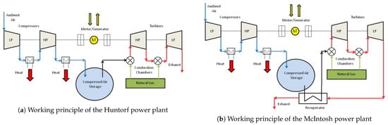
The CAES concept was patented during the 1940s, and had been studied for several years in Europe [55][66] before the installation of the world’s first CAES system (Huntorf power plant) by a German utility, Nordwestdeutsche Kraftwerke, in 1978 [56][67]. The Huntorf power plant consists of a two-stage compressor (40 bar and 70 bar) with intercooling for compressing air, a cavern of about 310,000 m3, about 600 m underground for storage, and a two-stage natural gas combustor with a rated power of 290 MW [57][58][68,69]. The Huntorf power plant is still in operation and runs on a daily cycle with 8 h of charge and 2 h of discharge. During the 1970s and 1980s, The US Energy Research and Development Agency (ERDA) and US National Science Foundation (NSF) initiated two major federally-supported programs to study and develop CAESs [55][66]. The results of these research projects and studies, for example, refs. [55][59][60][66,70,71], and further technological advancements, resulted in the commissioning of the first CAES power plant (McIntosh) in the USA in 1991.
The working principle of the Huntorf power plant and McIntosh power plant is similar (they are both diabatic systems), but the McIntosh system uses a recuperator to preheat the stored compressed air before it enters the combustion chamber (as shown in Figure 34), resulting in the system that is 10% more efficient than the Huntorf power plant. The two power plants described above are the only CAES systems currently in operation.
Techniques to make CAESs more efficient were studied already in the 1980s [61][62][63][64][65][72,73,74,75,76]. The topic received more focus after a European research project [66][67][68][77,78,79] proposed a new concept called advanced adiabatic CAES (AA-CAES). Other advanced CAES systems with isothermals are proposed in the literature [69][70][71][80,81,82]), but these are limited to theoretical analyses.
Around 2004, an innovative, 270 Megawatt, USD 400 million CAES project was proposed to be commissioned near Des Moines, Iowa in the USA. Unfortunately, after eight years of development, the project was terminated because of site geological limitations. The report [72][83] on the lessons from the project showed that the cost of building such a facility would be about 20% higher than a comparably sized, conventional natural gas-fired combined-cycle electric generation facility, and the project’s long-term economics looked favorable.
The world’s first advanced adiabatic CAES demonstration plant with an electric output of 90 MW was planned in Germany [73][84], but the project, after a decade of planning and feasibility studies, stopped due to lack of economic viability. Several other CAES projects seem to have started in Japan, Italy, and the UK [67][78], but they were stopped for either economic or technical reasons.
3.1. Energy Efficiency and Losses
The charging efficiency of diabatic CAESs is around 80%, and the discharge efficiency is about 70%, leading to a round-trip efficiency of about 55% (electricity to electricity). Additional fuel is required to complete the cycle. Therefore, the actual electrical efficiency after subtracting electricity that could have been produced with the fuel will not be above 45%.
Some of the theoretical studies show that the adiabatic CAES system with thermal energy storage subsystems can achieve round-trip efficiencies up to 70% [67][68][74][78,79,85]. Achieving a practical round-trip efficiency of 70% in the near future seems unrealistic because the rapid development and deployment of the CAES technology (required for better know-how and technological enhancement) have not happened yet.
The adiabatic CAES systems store the waste heat produced during the compression. There will be some system losses even when all the heat is effectively stored during charging. Adiabatic compression is limited to low pressures due to technical limitations on the temperature at the compressor outlet. Several compression stages and inter-cooling are required to compress air to high pressures (>4 MPa). Inter-cooling cools the compressed air temperature after the first compression stage and, thus, reduces the entry temperature and work required for the air to be compressed to further higher pressures.
The adiabatic CAES system would operate in a temperature regime lower than that of the existing Diabatic CAES, so it is hard to improve the discharge efficiency of the system beyond a few percentage points from the current level of 70%. For the systems to achieve round-trip efficiencies close to 70%, most of the heat of compression should be effectively reused using several compressors, intercoolers, storage units, reheat cycles, and efficient turbomachinery. This will significantly increase the cost of the system.
3.2. Typical Characteristics and Capacities
The two operational plants have a charge/discharge duration of 8/3 h (Huntorf) and 38/24 h (McIntosh). The system cost of charging components in a CAES system is typically not much smaller than the discharging system. The cost of compressors per MW electric charge is about half of the cost of turbines per MW discharge. To minimize the system cost, CAES is constructed to charge more slowly than when discharging [75][86].
The volume-specific storage density of compressed air is 5 kWh/m³ to 20 kWh/m³ for 50 bar to 100 bar pressure. Large, cost-effective storage facilities for pressurized air are essential for CAES systems. The two existing plants utilize salt domes as a storage facility for the compressed air, but other storage facilities such as abandoned mines and aquifers might also be used.
Unlike sensible heat storage, it would be difficult to make a modular design for CAES unless costly steel tanks are used to store the compressed air. Based on the experience of the two operational plants, the typical storage period can be hours to days. Typical storage losses are virtually none for diabatic CAES; adiabatic CAES will have some obvious thermal losses, but they will not be more than 0.5% of the total input energy.
3.3. Research and Development Perspective
The theoretical research in CAES technology is matured, and they all point to the fact that CAES has a high extrinsic value and is technically sound. However, the lack of commercial development has halted the progress of technology.
For adiabatic CAES to be feasible, there are two major challenges. There are no off-self electrically driven compressors that can handle large outlet temperatures, and there is a major challenge to store the high-temperature heat at the high-pressure levels.
4. Liquid Air Energy Storage (LAES)
Liquid air energy storage (LAES) or cryogenic energy storage stores energy as liquified air, as shown in Figure 45. Thermal energy is captured, stored, and recycled between the charge and discharge cycles. The charging cycle cools down the liquid to very low temperatures; this cooled liquid air can be stored efficiently in insulated, low-pressure vessels. When exposed to ambient temperatures, liquid air expands rapidly, and this energy is used to drive a turbine and create electricity without combustion.
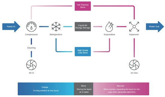
Figure 45.
Simplified diagram of Highview Power’s liquid air storage system. Source: Highview Power
®
.
Typically, liquid air production uses the well-known Joule–Thomson effect, where cryogenic coolers liquefy the air. The discharge cycle uses heat and expands the cryogen to produce power. During the discharge, a considerable portion of the exergy is lost in the form of cold. In commercially operational plants, the discharging cycle is combined with the liquefaction, so half of the energy lost during the discharge can be recovered for liquefaction.
Storing liquid air as an energy source also dates back to the 1900s when the Tripler Liquid Air Company developed liquid–air as an alternative fuel to compete with the steam and electric vehicles of those days [76][87]. The concept of using cryogenic systems as large-scale energy storage for load shifting started relatively late. In 1977, researchers at the University of Newcastle [77][88] proposed an LAES plant of 20 MW nominal capacity for peak shaving in the electricity grid. Subsequently, commercial companies Mitsubishi Heavy Industries [78][89], Hitachi [79][90], Highview Power Storage Systems [80][91], and several academic researchers, for example, [81][82][83][84][85][86][87][92,93,94,95,96,97,98], investigated and contributed to the maturity of the technology for load shifting.
Between 2008 and 2014, a pilot-scale demonstration plant was constructed on Scottish and Southern Energy’s Slough Heat and Power station in Slough, the UK. The results and experience from this pilot plant finally resulted in Pilsworth Grid-Scale Demonstrator Plant in Bury, Greater Manchester, in 2018 [88][99]. The Pilsworth plant, developed by Highview Power Storage Systems and backed by UK government funding, demonstrated that LAES could provide balancing services and support the grid during winter peaks. Highview Power currently operates two additional commercial LAES facilities with a nominal capacity of 50 MW in Vermont, USA, and Carrington, UK.
4.1. Energy Efficiency and Losses
The overall efficiency of liquid air production depends on the plant size and ranges between 11% and 50% [89][100]. The only storage energy loss of cryogen is the heat dissipation of cryogenic tank at the ambient pressure, which can be <1% per day in an insulated dewar using conventional insulation technologies [76][89][87,100].
Combined cycles store heat during compression (charging) and cold during the expansion (discharge). The stored cold is used during charging to increase the charging efficiency, and the stored heat is used during discharge to increase discharge efficiency. The recovered cold during discharge alone is insufficient to cool the compressed air to the lowest temperature [90][101], so additional electricity is needed for the cooling process. Round-trip efficiency of the LAES cannot be higher than 43% [86][97] when expended at the ambient temperature, even when waste cold during evaporation is effectively used. Round-trip efficiency can be further increased by hot storage. Not all stored heat energy can be efficiently used in the discharging process. Combined cycles that utilize thermal storage to store waste heat during charging (compression) and cold during the expansion (discharge) can achieve theoretical round-trip efficiency between 50% and 55% [91][102]. The overall system efficiency of the stand-alone LAES system is comparable to CAES and hydrogen storage systems.
LAES systems can integrate a wide range of external processes through hot and cold thermal streams or fuels for combustion to produce electricity, heating, and cooling at the same time [92][12]. If external cold sources are available, they can be used instead of electrical power for cooling during compression. The external heat source at temperatures higher than 400 K improves the discharge efficiency significantly. Such hybrid systems can achieve overall round-trip efficiencies of 60% to 70% [90][93][101,103].
4.2. Typical Characteristics and Capacities
LAES can provide 10 MW to 100 s MW of power and storage capacity in an order of GWh. The largest operational LAES facility has a power rating of 50 MW and a storage capacity of 250 MWh. Existing LAES systems have a storage duration of <10 h, but they can be built in a modular design, such that power and energy ratings can be changed independently. Further, there are no site constraint limits for the deployment of LAES.