Solar PV is proliferating, it also poses operational challenges attributable to its unpredictability and investment cost. Subsequently, solar PV exhibits variations inherent to renewable energy. These variations can emerge at any interval from seconds to minutes, necessitating the deployment of supplemental energy management devices. PV systems are additionally confronted by the cost differential during peak hours and the power quality given to the power grid. As a result, energy storage technologies are integral parts that can support PV systems to be able to provide energy for longer hours in the absence of sunlight.hotovoltaic (PV) is proliferating, it also poses operational challenges attributable to its unpredictability and investment cost. Subsequently, solar PV exhibits variations inherent to renewable energy. These variations can emerge at any interval from seconds to minutes, necessitating the deployment of supplemental energy management devices. PV systems are additionally confronted by the cost differential during peak hours and the power quality given to the power grid. Energy storage technologies are integral parts that can support PV systems to be able to provide energy for longer hours in the absence of sunlight.
- load shedding
- battery energy storage systems (BESS)
- photovoltaic (PV)
1. Solar Photovoltaic (PV) and Battery Energy Storage System
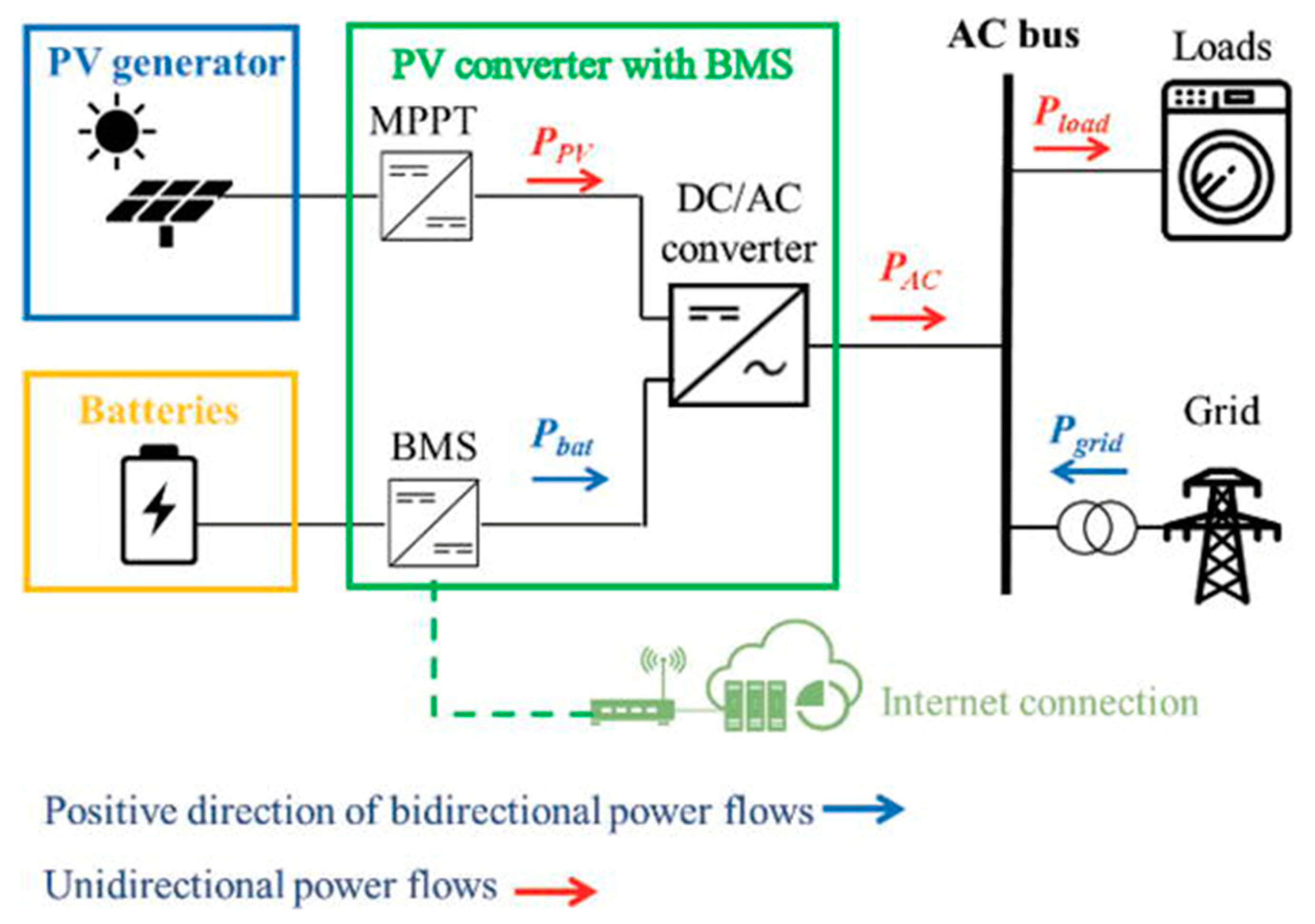
1.1. Selection and Deploying a Solar PV-Battery System
-
Amount of power and time of consumption;
-
Dimensions of available rooftop space;
-
Positioning and direction of solar PV panels.
1.2. Emplacement of the Solar PV-Battery System
-
The PV panels must not be exposed to any shade. Even if a single PV cell is obscured by objects such as branches, roof vents, or satellite dishes, many other PV cells will lose power. Due to variations in the flow of energy through the panel, the latter will have a significant influence on the output of the panel.
-
The efficacy of batteries can be affected by the temperature in the surrounding environment.
-
Batteries necessitate a setting or housing that is well-insulated and well-ventilated. A battery enclosure should ideally be placed on the south or west side of a South African building.
1.3. Connecting Solar PV-Battery System to the Power Grid
2. Battery Technologies
2.1. Lead–Acid Battery
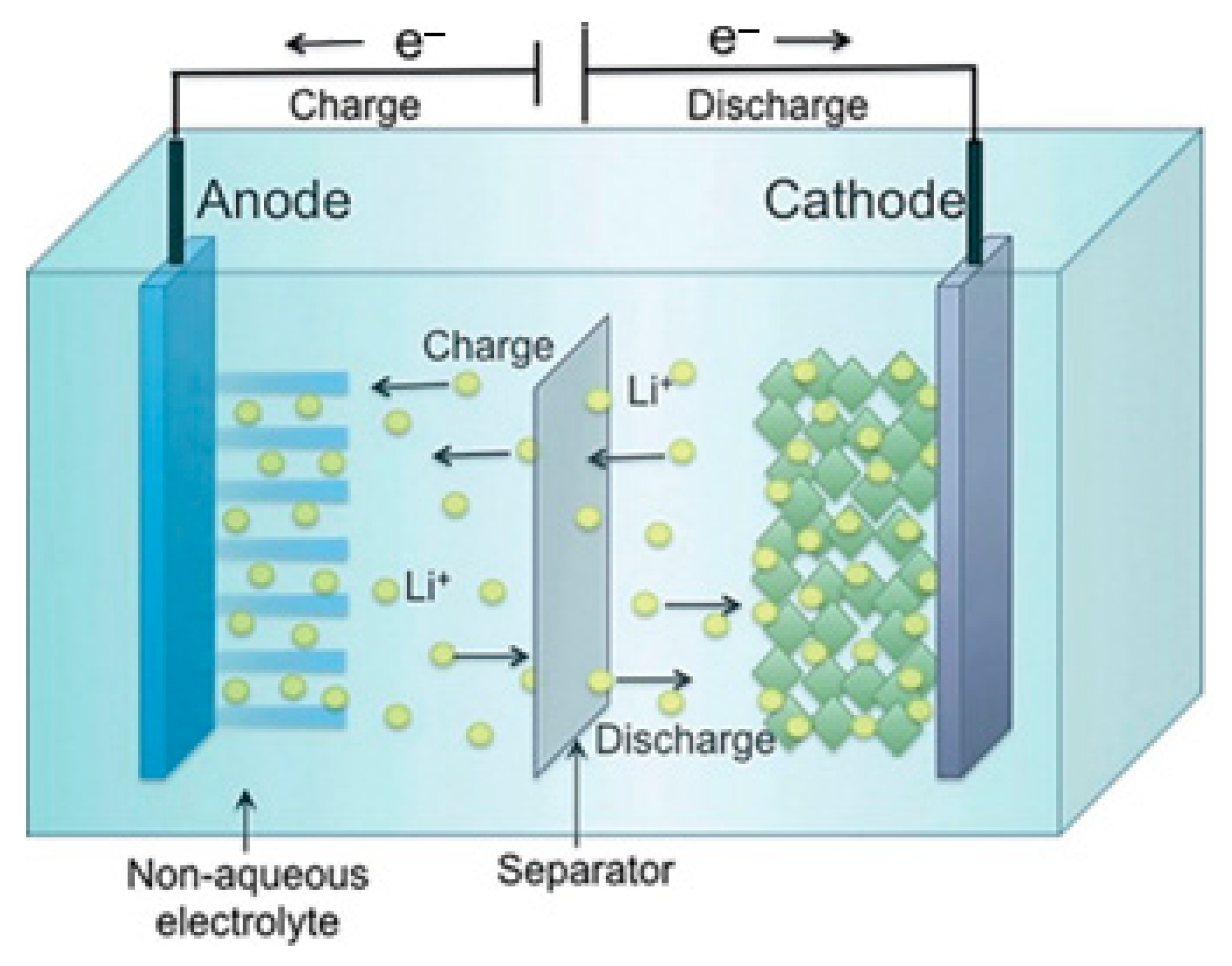
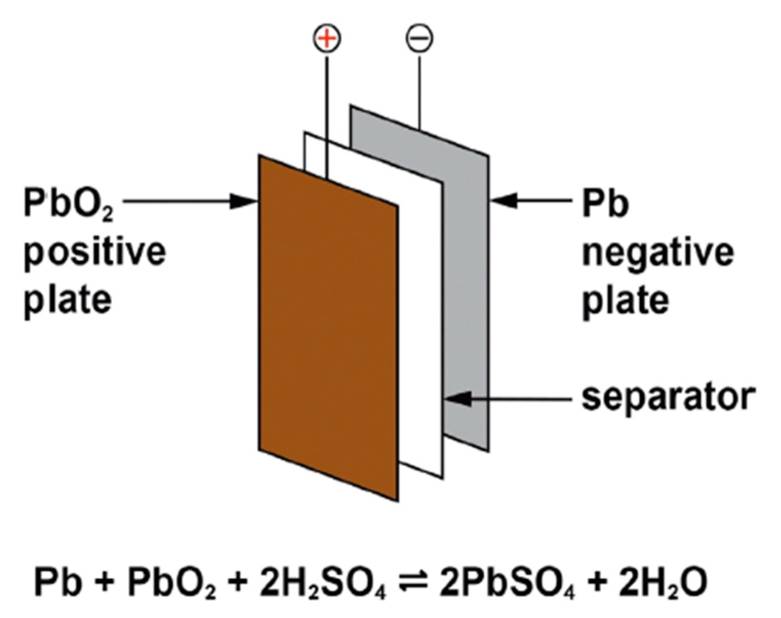
2.2. Lithium-Ion Battery
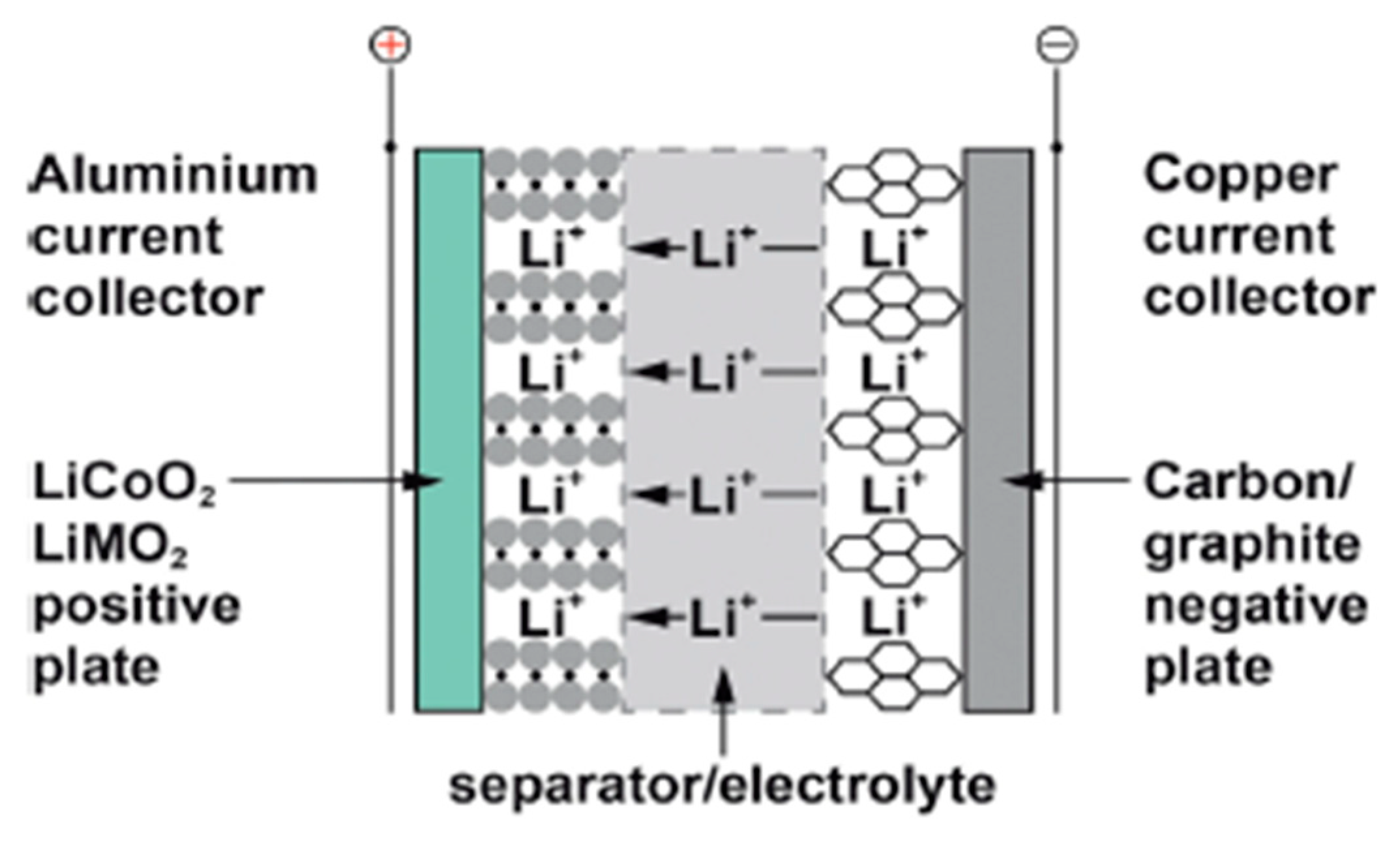
2.3. Sodium–Sulfur Battery
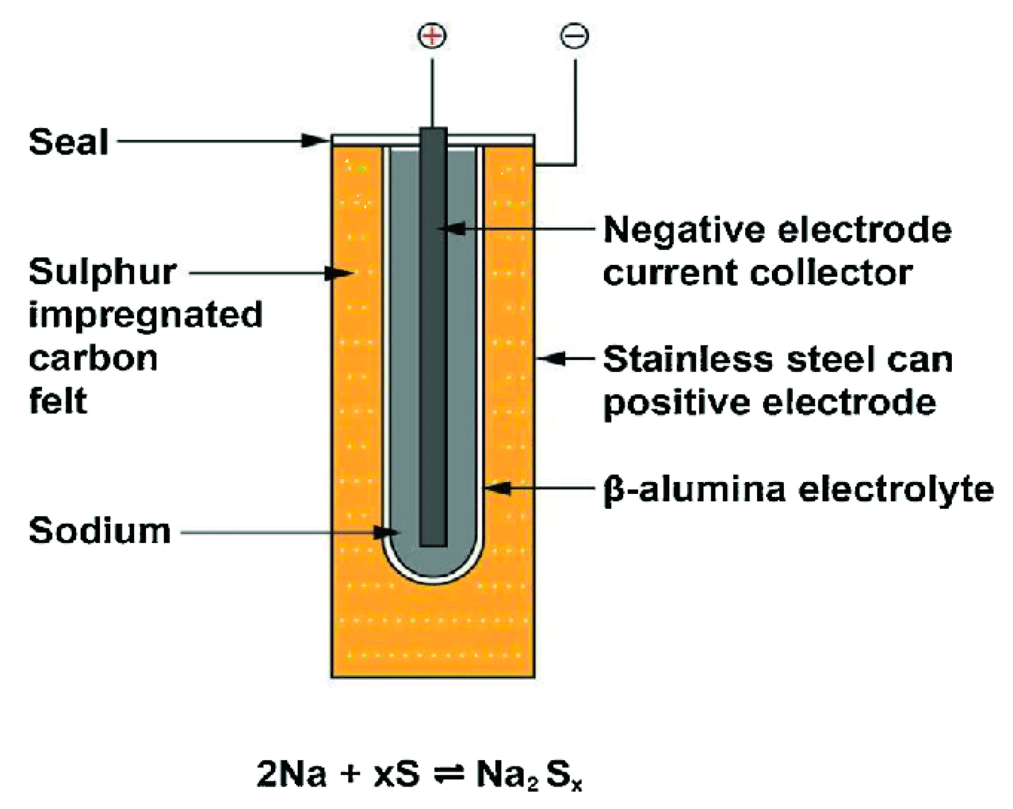
2.4. Sodium–Nickel Chloride Battery

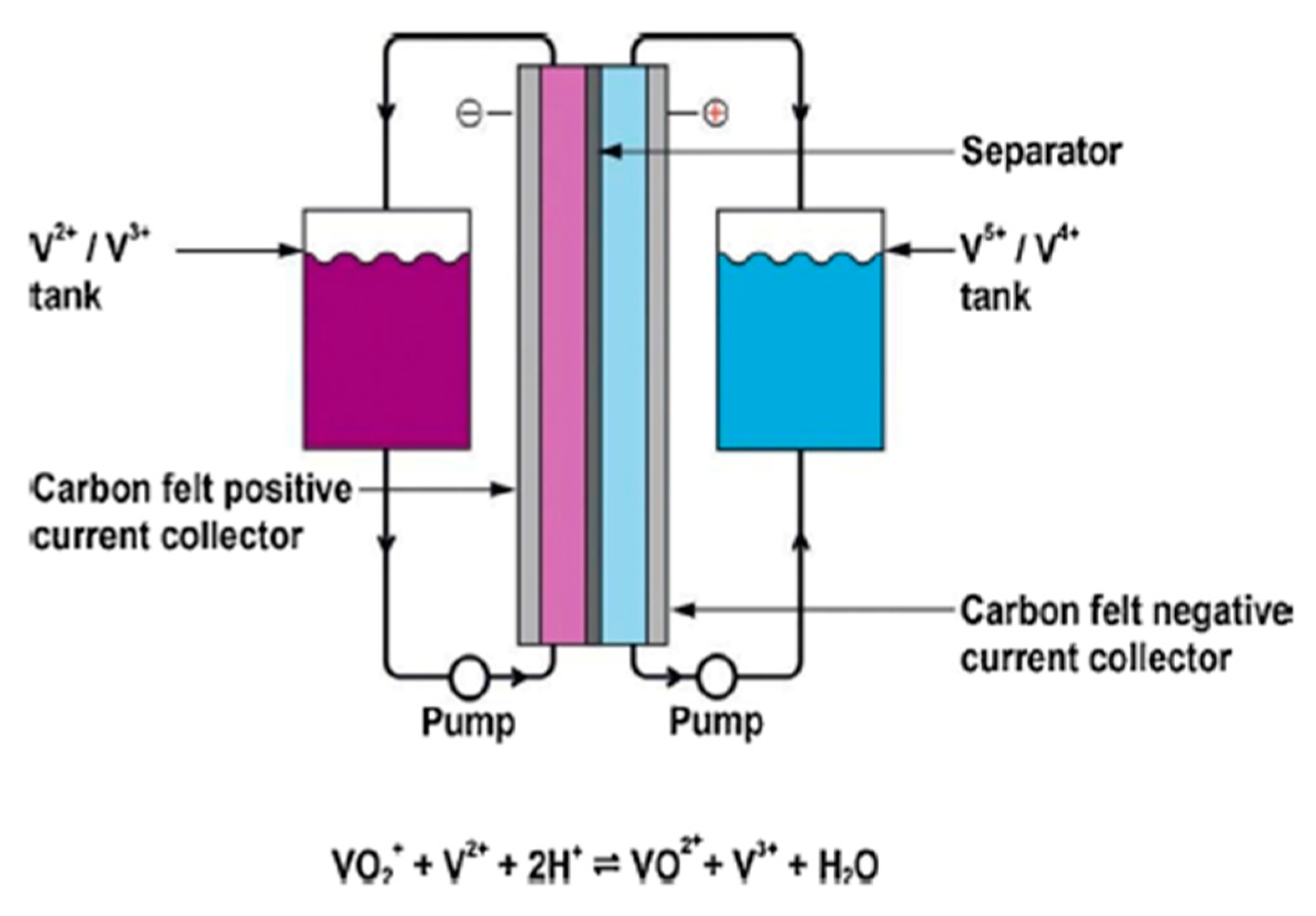
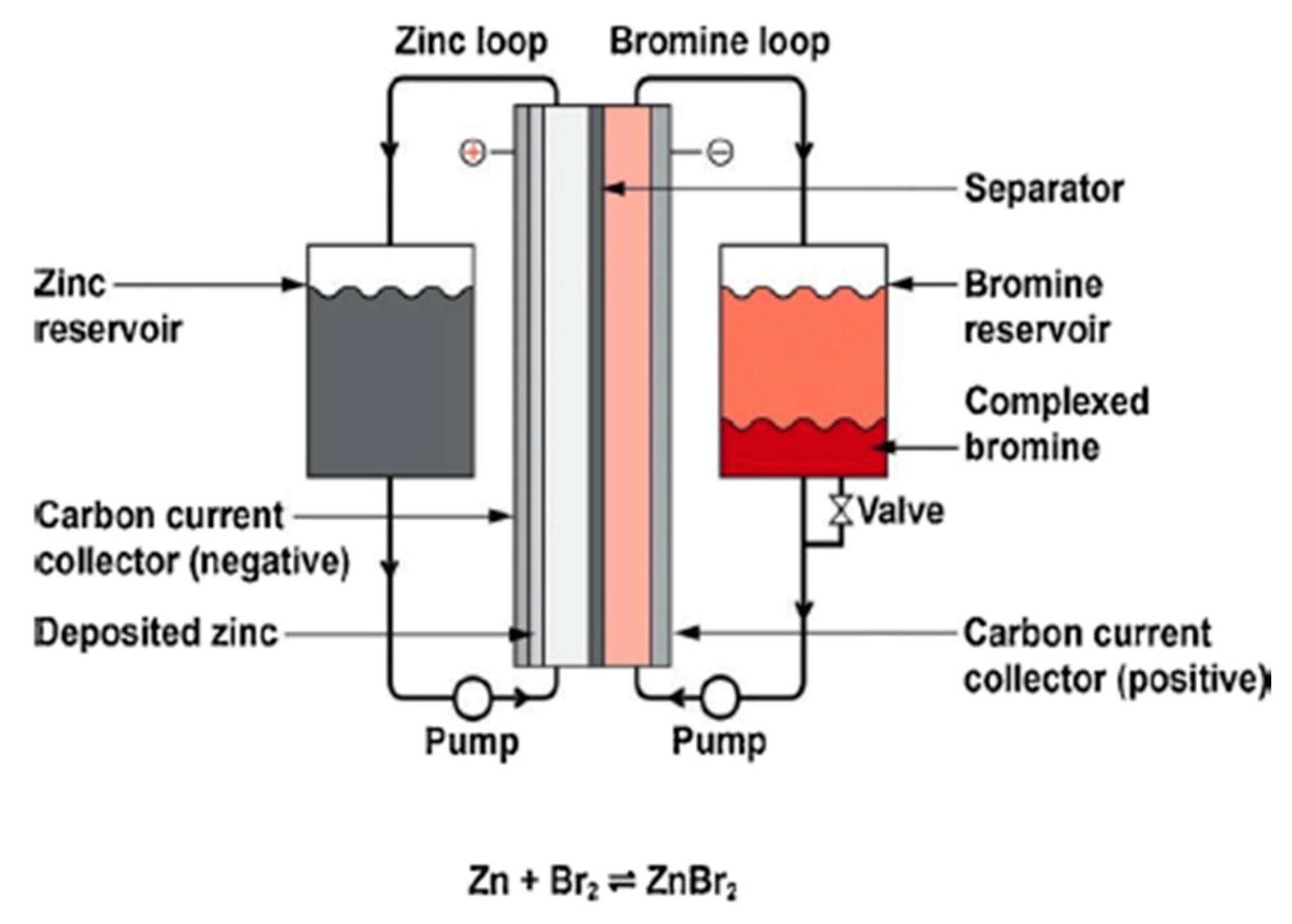
2.5. Flow Batteries
| Battery | Lead–Acid [23][4] | Lithium-Ion [24][5] | Sodium–Sulfur [25][6] | Sodium–Nickel Chloride [26][7] | Zinc–BROMINE [27][8] | Vanadium Redox [28][9] |
|---|---|---|---|---|---|---|
| Energy density (Wh/L) | 80–90 | 250–693 | 110 | 100–120 | 15–65 | 15–25 |
| Nominal cell voltage (V) | 2.1 | 3.6/3.7/3.8/3.85, LiFePO4 3.2 | 1.78–2.208 | 2.58 | 1.8 | 1.15–1.55 |
| Specific energy (Wh/kg) |
35–40 | 100–265 | 150 | 350 | 60–85 | 10–20 |
| Self-discharge rate | 1%/day | 5%/day | 20%/day | 5–20%/day | 10%/day | |
| Cycle durability | <350 | 400–1200 | 4500 | 4500 | >2000 | >12,000–14,000 |
| Charge/discharge efficiency | 50–95% | 80–90% | 80% | 85–95% | 75.9% | 75–80%< |
| Key Challenges and Limitations |
|
|
|
|
|
|
References
- Thirugnanam, K.; Kerk, S.K.; Yuen, C.; Liu, N.; Zhang, M. Energy Management for Renewable Microgrid in Reducing Diesel Generators Usage with Multiple Types of Battery. IEEE Trans. Ind. Electron. 2018, 65, 6772–6786.
- Venu, C.; Riffonneau, Y.; Bacha, S.; Baghzouz, Y. Battery Storage System sizing in distribution feeders with distributed photovoltaic systems. In Proceedings of the 2009 IEEE Bucharest PowerTech, Bucharest, Romania, 28 June–2 July 2009; pp. 1–5.
- Wang, Z.; Gu, C.; Li, F.; Bale, P.; Sun, H. Active Demand Response Using Shared Energy Storage for Household Energy Management. IEEE Trans. Smart Grid 2013, 4, 1888–1897.
- Kumar, D.; Zare, F.; Ghosh, A. DC Microgrid Technology: System Architectures, AC Grid Interfaces, Grounding Schemes, Power Quality, Communication Networks, Applications, and Standardizations Aspects. IEEE Access 2017, 5, 12230–12256.
- Lezhniuk, P.; Komar, V.; Rubanenko, O. Information Support for the Task of Estimation the Quality of Functioning of the Electricity Distribution Power Grids with Renewable Energy Source. In Proceedings of the 2020 IEEE 7th International Conference on Energy Smart Systems (ESS), Kyiv, Ukraine, 12–14 May 2020; pp. 168–171.
- 450-2020; IEEE Recommended Practice for Maintenance, Testing, and Replacement of Vented Lead-Acid Batteries for Stationary Applications—Redline. IEEE: Manhattan, NY, USA, 2021; pp. 1–115.
- P1361/D4; IEEE Draft Guide for Selection, Charging, Test and Evaluation of Lead-Acid Batteries Used in Stand-Alone Photovoltaic (PV) Systems. IEEE: Manhattan, NY, USA, 2013; pp. 1–41.
- 1188-2005; IEEE Recommended Practice for Maintenance, Testing, and Replacement of Valve-Regulated Lead-Acid (VRLA) Batteries for Stationary Applications—Redline. IEEE: Manhattan, NY, USA, 2006; pp. 1–49.
- Li, T.; Chen, Y.; Gou, H.Y.; Chen, X.Y.; Tang, M.G.; Lei, Y. A DC Voltage Swell Compensator Based on SMES Emulator and Lead-Acid Battery. IEEE Trans. Appl. Supercond. 2019, 29, 1–4.
- Freitas, D.C.C.; de Moraes, J.L.; Neto, E.C.; Sousa, J.R.B. Battery Charger Lead-Acid using IC BQ2031. IEEE Lat. Am. Trans. 2016, 14, 32–37.
- McKeon, B.B.; Furukawa, J.; Fenstermacher, S. Advanced Lead–Acid Batteries and the Development of Grid-Scale Energy Storage Systems. Proc. IEEE 2014, 102, 951–963.
- Chiu, H.; Lin, L.; Pan, P.; Tseng, M. A novel rapid charger for lead-acid batteries with energy recovery. IEEE Trans. Power Electron. 2006, 21, 640–647.
- Hannan, M.A.; Hoque, M.M.; Hussain, A.; Yusof, Y.; Ker, P.J. State-of-the-Art and Energy Management System of Lithium-Ion Batteries in Electric Vehicle Applications: Issues and Recommendations. IEEE Access 2018, 6, 19362–19378.
- Zhang, W.; Wang, L.; Wang, L.; Liao, C.; Zhang, Y. Joint State-of-Charge and State-of-Available-Power Estimation Based on the Online Parameter Identification of Lithium-Ion Battery Model. IEEE Trans. Ind. Electron. 2022, 69, 3677–3688.
- Al-Humaid, Y.M.; Khan, K.A.; Abdulgalil, M.A.; Khalid, M. Two-Stage Stochastic Optimization of Sodium-Sulfur Energy Storage Technology in Hybrid Renewable Power Systems. IEEE Access 2021, 9, 162962–162972.
- Saruta, K. Long-term performance of sodium sulfur battery. In Proceedings of the 2016 IEEE 2nd Annual Southern Power Electronics Conference (SPEC), Auckland, New Zealand, 5–8 December 2016; pp. 1–5.
- Hatta, T. Applications of sodium-sulfur batteries. In PES T&D 2012; IEEE: Manhattan, NY, USA, 2012; pp. 1–3.
- Manzoni, R. Sodium Nickel Chloride batteries in transportation applications. In Proceedings of the 2015 International Conference on Electrical Systems for Aircraft, Railway, Ship Propulsion and Road Vehicles (ESARS), Aachen, Germany, 3–5 March 2015; pp. 1–6.
- Marcondes, A.; Scherer, H.F.; Salgado, J.R.C.; de Freitas, R.L.B. Sodium-nickel chloride single cell battery electrical model—Discharge voltage behavior. In Proceedings of the 2019 Workshop on Communication Networks and Power Systems (WCNPS), Brasilia, Brazil, 3–4 October 2019; pp. 1–4.
- Benato, R.; Sessa, S.D.; Necci, A.; Palone, F. A general electric model of sodium-nickel chloride battery. In Proceedings of the 2016 AEIT International Annual Conference (AEIT), Capri, Italy, 5–7 October 2016; pp. 1–6.
- Challapuram, Y.R.; Quintero, G.M.; Bayne, S.B.; Subburaj, A.S.; Harral, M.A. Electrical Equivalent Model of Vanadium Redox Flow Battery. In Proceedings of the 2019 IEEE Green Technologies Conference (GreenTech), Lafayette, LA, USA, 3–6 April 2019; pp. 1–4.
- Vins, M.; Sirovy, M. Assessing Suitability of Various Battery Technologies for Energy Storages: Lithium-ion, Sodium-sulfur and Vanadium Redox Flow Batteries. In Proceedings of the 2020 International Conference on Applied Electronics (AE), Pilsen, Czech Republic, 8–9 September 2020; pp. 1–5.
