Your browser does not fully support modern features. Please upgrade for a smoother experience.
Please note this is a comparison between Version 2 by Conner Chen and Version 1 by Franc Mihalic.
The design of modern industrial products is further improved through the hardware-in-the-loop (HIL) simulation. An HIL model can bypass serious damage to the real object, reduce debugging cost, and, finally, reduce the comprehensive effort during the testing.
- hardware-in-the-loop (HIL)
- controller-in-the-loop (CIL)
- power hardware-in-the-loop (PHIL)
1. Introduction
During the system development process, using parts or complete hardware in the simulation loops is very important for the so-called hardware-in-the-loop (HIL) simulations. The real hardware (when available) is used in the simulation loop instead of strenuous and long-term testing of the control algorithms [1,2][1][2]. At the same time, HIL simulation also includes controller-in-the-loop (CIL) simulations, forming the backbone of the automotive, defense, marine, and space industries. This simulation is infallible in testing a component, such as an electronic control unit (ECU), and is connected to the simulation instead of the real equipment under control. The fact is that the actuators are hard to model, and, when they are available, can be incorporated into the simulation loop to improve the simulation.
Usually, the testing of the system and then its evaluation are run in real time. The control input is provided within the desired sampled period in such an embedded system. It is important to point out that the control signal is crucial for the stability of the system. HIL simulation as a tool for testing the control system has been present for the longest time in the aerospace industry: here, the software for flight control systems could be a safety critical issue, and the combination of all these aspects has encouraged its use in the following:
-
Intense pressure to reduce development cycles;
-
Safety requirements which require exhaustive testing of a control system before using on the real plant;
-
The need to prevent costly failures, either in-service or late in the design cycle;
-
Reduced cost and greater availability of off-the-shelf products for HIL simulation.
- Intense pressure to reduce development cycles;
- Safety requirements which require exhaustive testing of a control system before using on the real plant;
- The need to prevent costly failures, either in-service or late in the design cycle;
- Reduced cost and greater availability of off-the-shelf products for HIL simulation.
In the last half-century, HIL simulation has played an essential role in the field of flight simulation [3]. At the same time, broad use of this method can also be found in the testing of missile guidance systems [4]. Even before this, highly maneuverable aircraft technology (HiMAT) was developed by NASA [5]. Within this program, the use of advanced concepts was investigated (such as fly-by-wire and reduced static stability). Additional to NASA’s development of an area of high-fidelity HIL simulations, the USAF Phillips Lab has developed a laboratory to integrate component technologies and demonstrate spacecraft subsystem/payload level capabilities [6].
HIL simulation is developing fast from a system model design, synthesis, and simulation criterion. An HIL simulator is often a powerful tool in many applications, such as airplanes, missiles, and uncrewed aerial- or ground-traffic vehicles, where the autopilots play a crucial and vital role [7]. Through the HIL simulator, the embedded system is forced to operate in real time, such as in the real world with real inputs and outputs. For example, the autopilot fools the aircraft system into thinking that it is flying. Figure 1a shows a general block scheme of an embedded system where an HIL simulator is used for testing, while Figure 1b shows the necessary components of a simple HIL simulator.
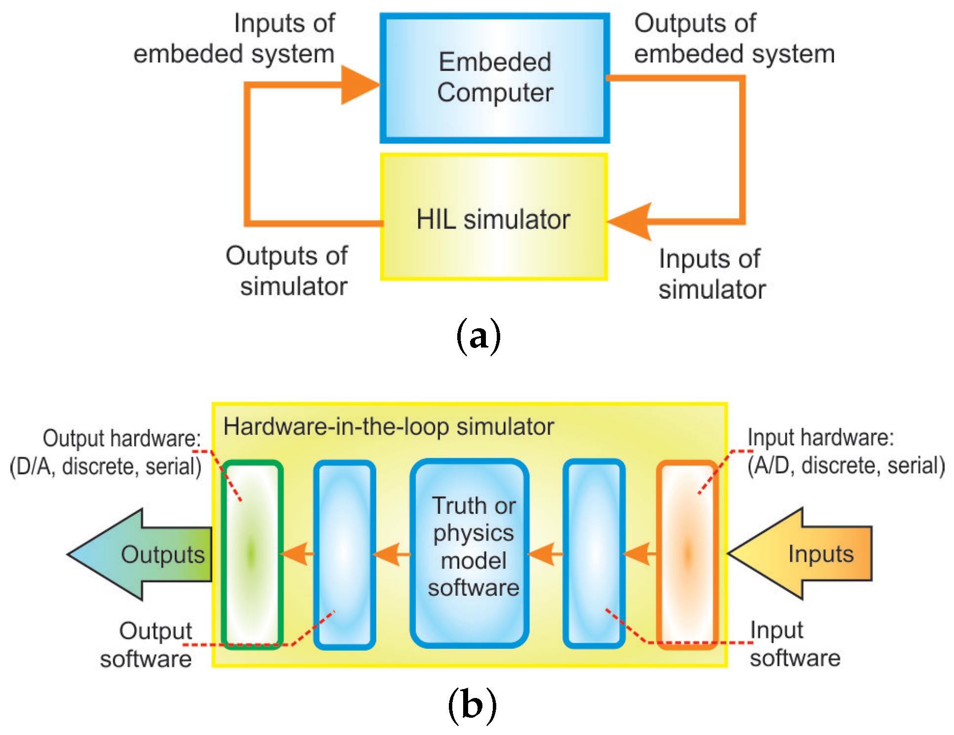
Figure 1. HIL simulator: (a) Block diagram of embedded system connected to a HIL simulator; (b) components of a simple HIL simulator [7].
Like Gomez in [7] already reported more than 20 years ago, giving monetary judgments about the HIL simulators is tough and ungrateful. Unfortunately, there is almost no off-the-shelf HIL simulator for sale, although a couple of products and providers can come close. For example (according to [7]), if the first self-designed simulator in the mid-1990s cost slightly over EUR 100,000 (with 100 inputs and outputs), then the second identical unit cost about EUR 25,000 to build. This was considered a bargain compared to the multi-million dollar unmanned aerial vehicles (UAVs) they were developing—if the HILS prevented the crash of just one UAV, the company would get its money’s worth. There was another, even more, valuable benefit: a HILS allows the software to be developed and tested without waiting for the actual hardware to be built (or, in this case, built and flown).
In recent years, wpeople have faced very complex power electronic systems, electric drives, and their control. Their use is growing significantly in distributed power generation, such as home and industrial electronics, traction, automotive, hybrid vehicles, aerospace systems, and the marine industry. Based on the significant progress in the field of power semiconductors, and various platforms, such as microcontrollers, microcomputers, and microprocessors, field programmable gate array (FPGA), and digital signal processor (DSP), wpeople are witnessing high-performance electric drives [8]. Advanced software tools, such as MATLAB/Simulink [9] and real-time simulators [10], are used broadly in many engineering fields, i.e., education, research groups, and industry. The involvement of real-time simulations in modern engineering ensures an excellent aid for academia and researchers. It is, however, also very beneficial to have the HIL simulation become a part of the control development toolset [11].
2. V-Models for the Development Procedures and Functional Safety
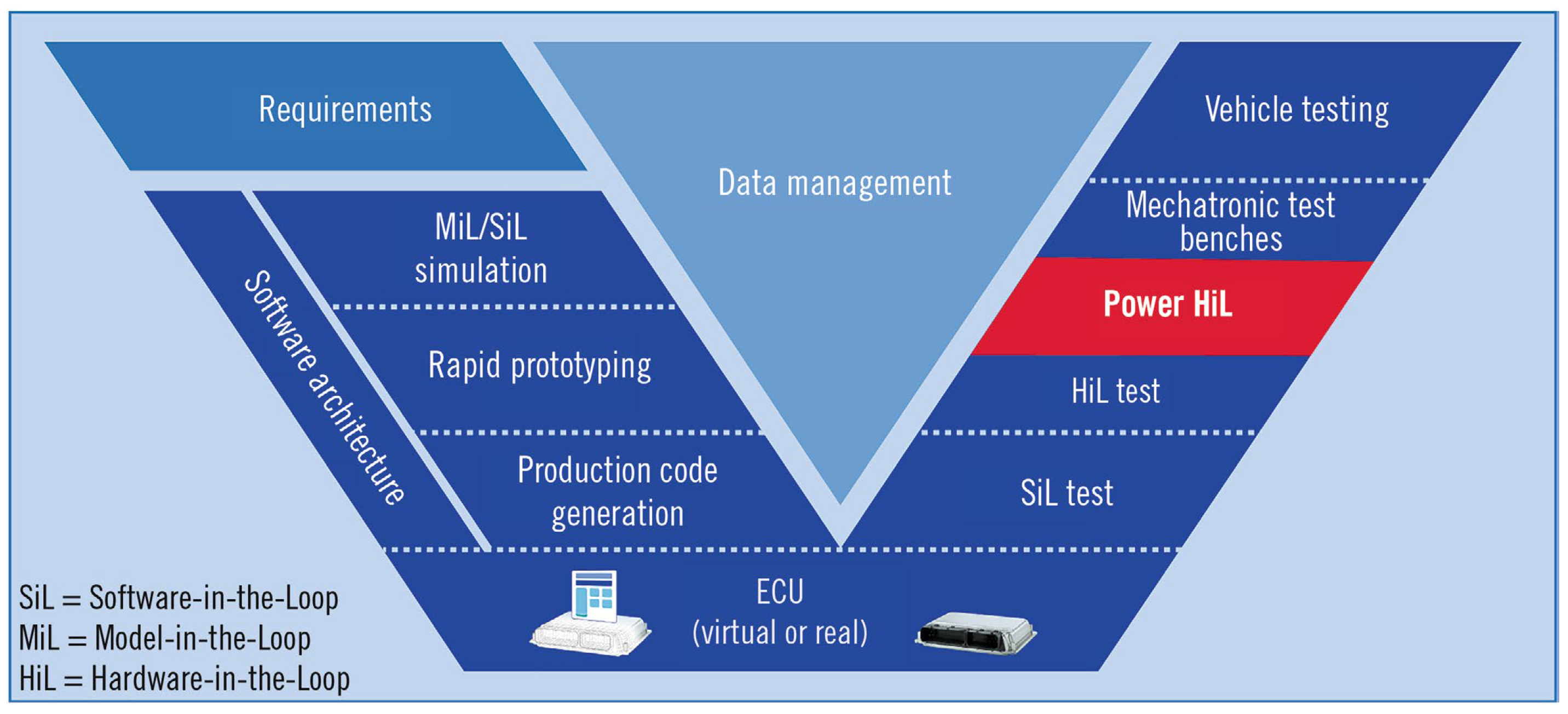
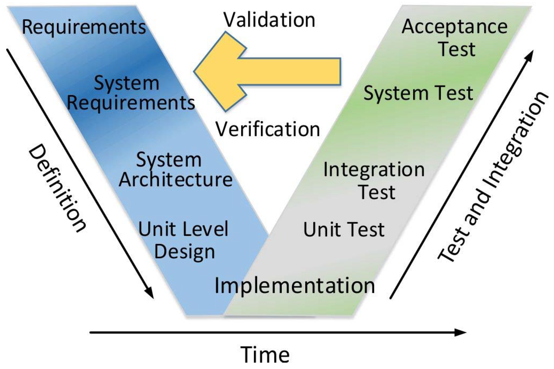
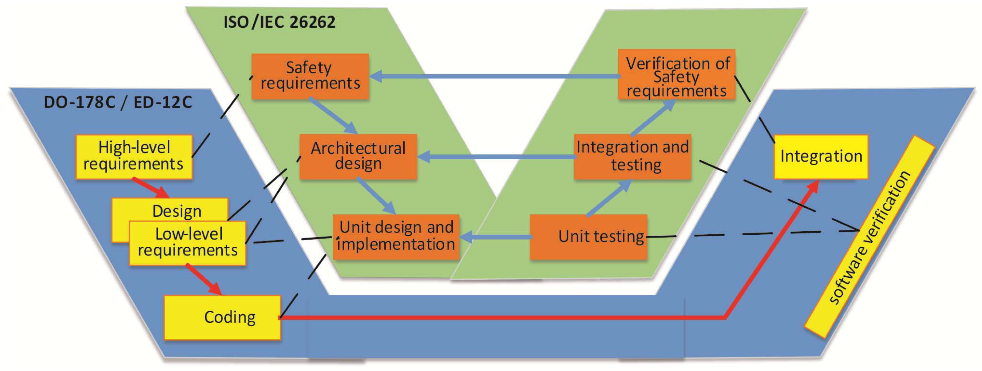
The development of medical equipment also requires comprehensive and careful testing procedures as a critical step against validation and successful certification. A new embedded deep brain recording system is reported in [12]. Real-time communication is running during the signal analysis in this rigorous environment. The considered HIL testing system is built on a single board DSP computer (SBC) with high performance, generating numerous analog signals. The development process is shown in Figure 2, where the integrated requirements are on the left side of the typical V model and the corresponding test methods are on the right side. While the requirements are in the blue color, the implementation of them is in green, and the red color on the right side is reserved for the test methods. A standard Ethernet interface is used for communication; the control interface is written using Java, and is not dependent on the computer’s platform. In the automotive industry of the modern era, electric mobility is a significant trend, where power electronics are the main component. Through sophisticated power electronics systems with embedded control, the supplying voltage is transformed to the necessary AC or DC voltages. In [13], dSpace offers safe testing through the power hardware-in-the-loop (Power HIL or PHIL) systems, where a relevant emulation is used for the simulated signals (Figure 3) to validate the ECUs with software-in-the-loop (SIL) in HIL environments. The ECU software is, in a SIL solution, certified in a virtual environment. The ECU software can then be approved with no ECU hardware at all. The requested object model and the software run on a PC using particular tools. The test execution is also possible in the cloud with included scaling as well. A design methodology (called functional safety) is accepted widely in all significant fields of industry to avoid the undesirable risk of physical injury or damage to people’s health. The human aspect plays an essential function during the development of hardware and software, making it practically impossible to be error-free [14]. The growing complexity of modern power electronics systems demands strong electrical safety requirements and tests of all components in road vehicles. However, it must assure strong functional safety performance as well. A basic standard relevant to most fields of the industry is dealing with functional safety [15]. However, different industry domains require typical requirements; therefore, supplemental standards are needed for functional safety. A functional safety standard for vehicles in the automotive industry is IEC/ISO 26262 [16]. On the contrary, in aerospace, there are two standards: DO-178/ED-12 for software certification requirements [17], and DO-254/ED-80 for the electronic hardware [18]. More precisely, the DO-178/ED-12 and DO-254/ED-80 are not, in fact, standards, but the relevant authorities, the Federal Aviation Administration (FAA) and European Aviation Safety Agency (EASA), treat them as de facto standards. Figure 4 shows the functional safety V-model development process, which begins with the product’s requirements’ collection and presents the foundation for standards. The system’s architecture follows these requirements. The system is divided into separate units for their development. The implementation is enabled by writing the software (coding) and hardware design. Next, the testing of each unit as an autonomous system or software follows. The integration tests are provided for verifying the units’ joint operations. The system test follows this step, combining all units into the entire system or product. Finally, for a successful functional safety development process, the validation of the designed system is concluded with an acceptance test to comply with the requirements. While different industries need specific standard requirements, some parallels are always possible: Figure 5 shows primary analogies for automotive and aerospace. In addition to the terminology, the documents, processes, and methods are different. However, the documentation can be reused for transferring between the fields. Nevertheless, the guidelines must be considered and followed during the whole process, particularly in aerospace, where suitable authorities, such as EASA and FAA, must be included in the project within the initiation phase. To summarize, in the case of safety-critical applications in the industry, functional safety and HIL simulation are the most significant methods for reliable production.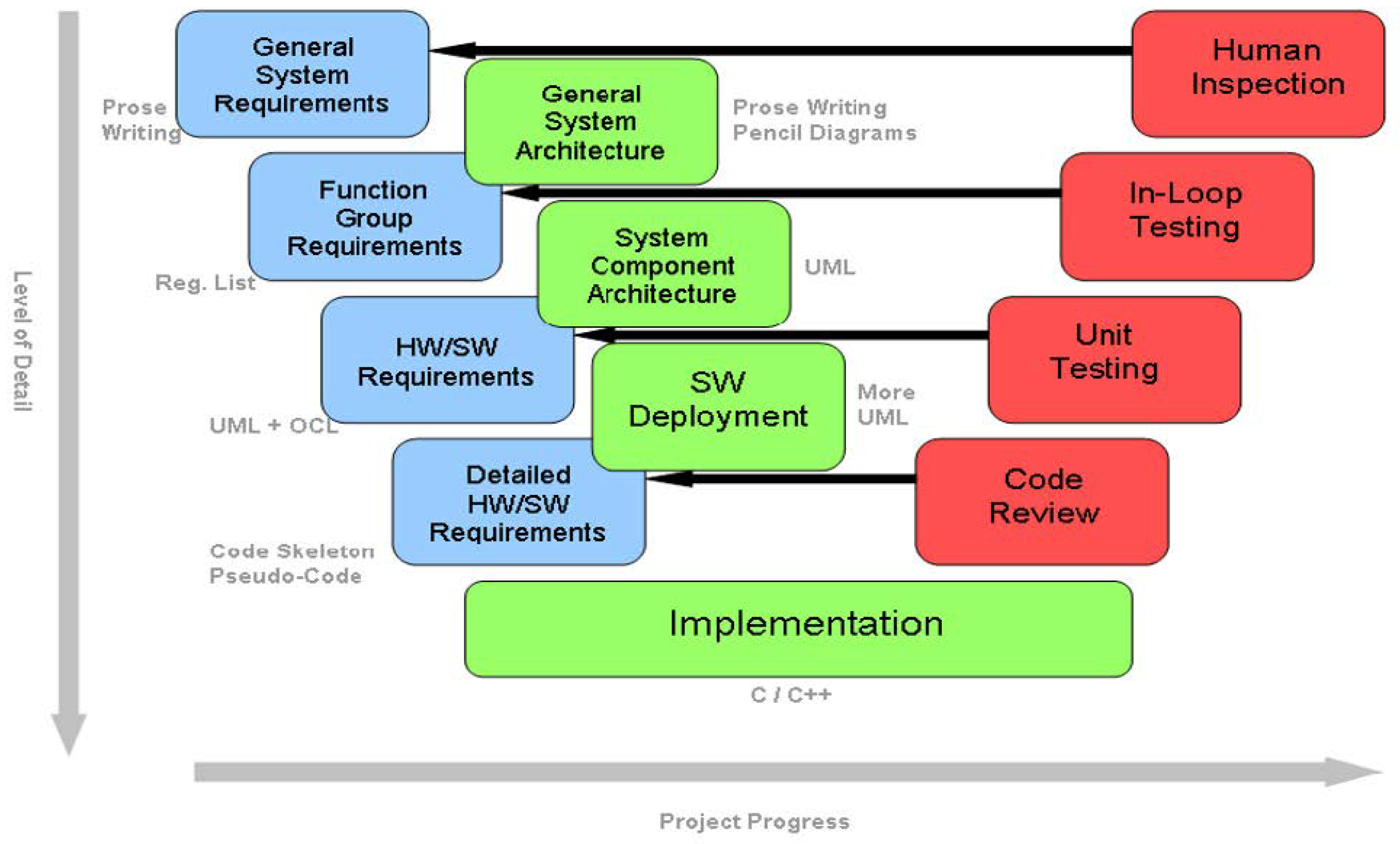
References
- Maclay, D. Simulations get into the loop. IEE Rev. 1997, 43, 109–112.
- Bacic, M. On hardware-in-the-loop simulation. In Proceedings of the Conference on Decision and Control/European Control Conference, Seville, Spain, 12–15 December 2005; pp. 3194–3198.
- Dillard, A.E. Real-time operational evaluations using advanced flight simulators. In Proceedings of the Digital Avionics Systems Conference, Bellevue, WA, USA, 31 October–7 November 1998; pp. E16-1–E16-8.
- Pace, P.E.; Nishimura, B.H.; Morris, W.H.; Surratt, R.E. Effectiveness calculations in captive-carry HIL missile simulator experiments. Trans. Aerosp. Electron. Syst. 1998, 34, 124–136.
- Evans, M.B.; Schilling, L.J. The Role of Simulation in the Development and Flight Test of the HiMAT Vehicle. NASA Technical Memorandum 84912. 1984. pp. 1–37. Available online: https://ntrs.nasa.gov/citations/19840013469 (accessed on 30 May 2022).
- Leitner, J. Space technology transition using hardware in the loop simulation. In Proceedings of the Aerospace Applications Conference, Aspen, CO, USA, 10 February 1996; pp. 303–311.
- Gomez, M. Hardware-in-the-Loop Simulation. Available online: http://jmargolin.com/uavs/jm_rpv2_npl_14.pdf (accessed on 26 May 2022).
- Ingalalli, A.; Satheesh, H.; Kande, M. Platform for hardware in loop simulation. In Proceedings of the SPEEDAM, Capri, Italy, 22–24 June 2016; pp. 41–46.
- Simulink; MathWorks, Inc.: Natick, MA, USA; Available online: https://www.mathworks.com/products/simulink.html (accessed on 12 June 2022).
- Simulink Real-Time; MathWorks, Inc.: Natick, MA, USA; Available online: https://www.mathworks.com/products/simulink-real-time.html (accessed on 12 June 2022).
- Hanselmann, H. Hardware-in-the-loop simulation testing and its integration into a CACSD toolset. In Proceedings of the Computer-Aided Control System Design Symposium, Dearborn, MI, USA, 15–18 September 1996; pp. 152–156.
- Vogt, S.M.; Klostermann, M.; Kundu, A.; Andruschenko, S.; Hofmann, U.G. Hardware-in-the-loop testing for closed-loop brain stimulators. In Proceedings of the ECIFMBE, Antwerp, Belgium, 23–27 November 2008; pp. 1128–1132.
- Puschmann, F. Safe testing through power hardware-in-the-loop systems. ATZ Electron. Worldw. 2021, 16, 50–53.
- Milanovič, M.; Rodič, M.; Truntič, M. Functional safety in power electronics converters. In Proceedings of the EDPE, Dubrovnik, Croatia, 4–6 October 2017; pp. 1–14.
- IEC 61508-1:2020; Functional Safety of Electrical/Electronic/Programmable Electronic Safety-Related Systems—Part 1: General Requirements, Edition 2.0. IEC: Geneva, Switzerland, 2010. Available online: https://webstore.iec.ch/publication/5515 (accessed on 6 June 2022).
- ISO 26262-1:2011; Road Vehicles—Functional Safety—Part 1: Vocabulary. International Organization for Standardization: Geneva, Switzerland, 2011. Available online: https://www.iso.org/obp/ui/#iso:std:iso:26262:-1:ed-1:v1:en (accessed on 6 June 2022).
- RTCA Inc. DO-178C/ED-12C: Software Considerations in Airborne Systems and Equipment Certification; Technical Report DO-178C; RTCA Inc.: Washington, DC, USA, 2012; Available online: https://en.wikipedia.org/wiki/DO-178C (accessed on 6 June 2022).
- RTCA Inc. DO-254, Design Assurance Guidance for Airborne Electronic Hardware; RTCA Inc.: Washington, DC, USA, 2000; Available online: https://en.wikipedia.org/wiki/DO-254 (accessed on 6 June 2022).
More