Your browser does not fully support modern features. Please upgrade for a smoother experience.
Please note this is a comparison between Version 1 by Mohammad J. Mirzaali and Version 2 by Sirius Huang.
Additive manufacturing (AM, also known as 3D printing) is an advanced manufacturing technique that has enabled progress in the design and fabrication of customised or patient-specific (meta-)biomaterials and biomedical devices (e.g., implants, prosthetics, and orthotics) with complex internal microstructures and tuneable properties. Several design guidelines have been proposed for creating porous lattice structures, particularly for biomedical applications.
- additive manufacturing
- biomaterials
- metals
- 3d printing
1. Introduction
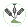
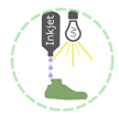
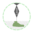
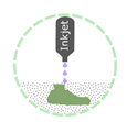
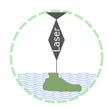
Additive manufacturing (AM, also known as 3D printing) technologies are among the most feasible advanced manufacturing options to create complex structures for use in technology-driven industries, such as healthcare [1], automotive [2][3][2,3], and aerospace [4]. AM, being different from other manufacturing methods, such as subtractive and formative methods, results in less scrap and waste of materials and allows for lightweight complex structures, often hollow or porous, thus requiring less material input and energy input during their fabrication and service. Seven categories of AM, namely, binder jetting, directed energy deposition, material extrusion, material jetting, powder bed fusion, sheet lamination, and vat photopolymerisation, have been recognised and defined in the ISO/ASTM 52900 standard [5].
Not all AM processes in the ASTM classification are equally developed and used for medical devices and biomaterial fabrication [6]. Here is a summary of the capabilities, limitations, and pros and cons of conventional processes and associated materials (e.g., metals and their alloys, polymers, and ceramics) used in the fabrication of biomaterials (Table 1) in terms of printing speed, part sizes, degree of anisotropy, achievable resolution, the possibility of embedding cells in feedstock materials, the need for support, the need for post-processing, and costs. The success of each of these 3D printing processes relies, to a large extent, on the employment of optimised or suitable process parameters within the capabilities of the available AM machines that are associated with specific AM processes.
Table 1.
Summary of the different AM techniques, useable materials, their pros and cons, and their biomedical applications.
| Techniques and Materials | Pros | Cons | Biomedical Application | ||
|---|---|---|---|---|---|
Material Deposition 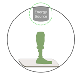 |
 |
Material Extrusion (FDM)
|
While AM offers almost unlimited possibilities to part designers, there are several constraints in the structural design of lattices that limit the theoretical ability of AM to fabricate porous structures with highly complex geometries. Several inherent limitations related to the processability of the designed part also exist in AM methods, which has led to the introduction of several guidelines to manage these constraints and limitations [13]. Some of these constraints are recognised as minimum feature size (e.g., wall thickness, edges, and corners), the orientation of lattice structures on the build plate for self-overhanging, support materials, and support removal [14].
As an example, in powder bed fusion (PBF) techniques, overhanging structures, which are defined as parts of lattice structures that are not self-supported, can result in undesirable defects in lattice structures [15][16][15,16]. There are no underlying layers or solidified sections to support these overhanging parts during their fabrication, which is why the choice of orientation during building is critically important. The overhanging structure also depends on the critical fabrication angle [15]. Sacrificial support materials, therefore, need to be used for overhanging structures below a specific fabrication angle. These sacrificial support materials need to be removed (e.g., in PBF techniques) or washed away (e.g., in vat photopolymerisation techniques) from the structures during post-processing, which may damage additively manufactured parts. To compensate for that and achieve optimum results with fewer support materials, the parts need to be designed with self-supported struts in lattice structures. Restricted build envelopes and the application of a single material in the manufacturing process of metallic materials can also be specified as other limitations, although achievable sizes have been considerably increased in recent years, and combinations of materials have become possible, e.g., by means of a recoater. In some cases, the limitation of a combination of materials can be resolved by alloying elemental metallic powders [17]. This limitation can also be overcome by using multiple nozzles in extrusion-based AM techniques.
Creating the geometrical design of a lattice structure is the first step in designing AM lattices. Lattice structures can be broadly classified as open-cell or closed-cell cellular structures. Because it is not possible to remove the residual material (e.g., entrapped powder particles in the case of PBF processes or supports in vat photopolymerisation processes) in closed-cell lattices, open-cell lattices are mostly chosen for fabrication using AM techniques. There are various proposed design principles regarding the geometrical arrangement of lattice structures (an overview is provided in Table 2). In some cases, we may combine two or more of these design methods to obtain a more desirable lattice structure.
Table 2.
Summary of the different approaches for the geometrical design of lattices.
| Design Strategy | Method | Geometry/Mechanism Example | Unique Feature | Caution in 3D Printability | ||||||
|---|---|---|---|---|---|---|---|---|---|---|
| Library-based | Ordered unit cells |
|
|
|
|
|
||||
 |
||||||||||
| Disordered unit cells | Directed Energy Deposition ( |
|
|
|
|
|
|
|||
 |
Material Jetting (Polyjet)
|
| ||||||||
| Topology optimisation |
| Analytical mathematical models and computational approaches to design and obtain optimised microstructures |
|
|
|
|
||||
|
|
Powder-based 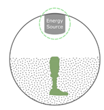 |
 |
PBF (SLS, SLM, DMLS, EBM)
|
|
|
|
|||
 |
Binder Jetting
| |||||||||
| Bio-inspired design | Bio-inspired designs |
|
|
|
| |||||
| Image-based |
|
|
|
|
|
|||||
Liquid-based 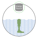 |
 |
|||||||||
| Meta-biomaterials | Designer material or mechanical metamaterial | SLA
|
|
|
|
|
||||
 |
DLP
|
In addition to selecting the proper AM techniques and suitable printing parameters, the microarchitecture design of biomaterials is one of the critical aspects of their development. It is often necessary to design porous or lattice structures for biomedical applications. This implies that the morphologies and sizes of the pores of biomaterials must be fully open and interconnected to allow for the transport of nutrients and oxygen to cells [6][7][8][6,7,8].
The advent of AM technologies has provided unique opportunities for the accurate arrangement of the sizes and internal architectures of pores at a microscopic level and to produce organic geometries with complex internal architectures and passages [9][10][11][9,10,11]. This is one of the most important merits of AM over conventional fabrication technologies, such as casting and moulding [12], in which the designer has virtually no control over the precise details of the internal geometries of porous materials.
2. Geometrical Design of Lattices
|
|
|
||
| Kinematic or compliant mechanism-based designs |
|
|
2.1. Library-Based Design
Computer-Aided Design (CAD), implicit surfaces, and image-based design can be categorised as traditional design strategies [18]. Open-source or commercial CAD tools/software have been used to develop CAD-based designs. These designs may then be transformed into the standard tessellation language (STL) format before going through the manufacturing process. In some cases, STL files can also be accessed through a software package installed on the 3D printing machine in order to control or modify the process parameters prior to or during printing. The final AM lattice structures can be generated by adjusting the process parameters of the input design file and setting the support material within the entire porous media.
Recently, other approaches (e.g., the single point exposure scanning strategy [19] and vector-based approach [20] for selective laser melting (SLM) printing or voxel-based approach [21] for Polyjet printing) have been proposed, which can boost the fabrication speed of an object with even more geometrical complexities. This is because the STL files of designs with too many complexities and details are often very large. The designs resulting from these approaches usually have smaller file sizes, thus allowing for easier file manipulation. These approaches, therefore, enable the process engineer to load large files with detailed features in the 3D printing software.
A unit cell can be identified as the smallest feature size in lattice structures with periodic microstructures. Unit cells create an ordered design by tessellating in a 2.5D plane (i.e., extruded in a 2D plane) or 3D space. Unit cells have already been identified in various forms, such as cubic or prismatic unit cells. They can be broadly categorised into two major groups, namely, beam-based and sheet-based unit cells. No specific repeating unit cells can be seen in lattices with irregular or random microstructures.
2.1.1. Beam-Based Unit Cells
One of the most common geometries for producing metallic or non-metallic lattice structures is the beam- or strut-based design, which includes beam-based unit cells that repeat spatially in 3D space. By reshaping the geometry, for example, by changing the size and thickness of struts and reforming the topology or connectivity of recurrent unit cells, the overall physical characteristics of the lattices, such as the relative density, pore size, and pore geometry, can be adjusted accordingly [22][23][22,23]. Body-centred cubic (BCC), face-centred cubic (FCC), and their variations (analogous to crystalline structures [24][25][24,25], cubic, diamond, and octet-truss) are just some examples of well-known strut-based topologies [26].
From a micro-mechanical viewpoint, lattice structures can be classified into two categories, namely, bending-dominated and stretching-dominated unit cells. Stretching-dominated unit cells are typically stiffer and have higher mechanical strength than bending-dominated ones [27]. However, achieving a fully stretch-dominated unit cell is nearly impossible, as some areas of the struts in a unit cell can experience bending loads. Strut-based unit cells can be characterised by their Maxwell number [28].
2.1.2. Surface-Based Unit Cells
Sheet-based unit cells belong to the category of implicit surface designs, in which mathematical equations define pore configurations. Triply periodic minimal surfaces (TPMS) are specific classes of sheet-based unit cells that provide high flexibility in the design of lattice structures [29][38]. The full integration of pores in TPMS makes them suitable for use in scaffold designs in tissue regeneration and tissue ingrowth applications [29][30][31][38,39,40]. TPMS-based porous structures also have a zero-mean surface curvature that can be considered a unique property [8]. It must be emphasised that the fabrication of additively manufactured TPMS geometries with high quality is a challenging procedure. This limits the number of available TPMS designs with limited porosity. Some TPMS geometries, such as primitive, I-WP, gyroid, and diamond designs, can nevertheless be realised.
2.1.3. Disordered and Random Network Designs
The arrangement of unit cells in lattice structures can be disordered, where the types or dimensions of the cells change within the object. As an example of such disordered systems, functionally graded structures can be designed, where pore sizes vary within the lattices. AM of graded porous structures has recently become prevalent [32][33][41,42], particularly in biomedical engineering [34][35][43,44]. One crucial reason for this increasing interest is the feature that causes a smooth stress distribution in the product to avoid stress concentrations at abrupt geometrical alterations. However, their geometrical complexities cause the AM of graded arrangements to be challenging, particularly when they feature more stochastic or disordered graded designs. This can result in the manufacturing of struts that are incapable of self-support, resulting in a poor AM outcome.
In contrast to uniform lattice structures, disordered lattice structures have several advantages. First, they can be designed to exhibit a broader range of (e.g., mechanical) properties rather than a particular targeted value. Therefore, the range of achievable properties can be expanded using random networks and may realise smooth variations in properties. An example is the rational design of microstructures to regulate elastic mechanical properties separately (i.e., the duo of elastic stiffness and Poisson’s ratio) [36][37][31,45]. The theoretical upper limits for the mechanical properties of lattices in 2D or 3D have been defined by Hashin and Shtrikman [38][46]. It has been observed that the application of lattices with anisotropic microstructures can enhance these theoretical upper bounds [39][47]. The second advantage is that random networks are less susceptible to local defects created during the AM process due to their stochastic nature. Third, their design process is much more straightforward than that for uniform and ordered networks. In ordered networks, the structural integrity and assembly of unit cells are fairly challenging tasks. In contrast, it is easier to combine several types of unit cells in random network lattices, such as combining stretch-dominated unit cells with bending-dominated unit cells.
2.2. Topology Optimisation Designs
Topology optimisation (TO) can be defined as the application of mathematical models to design optimised arrangements of microstructures of porous structures to obtain desired and optimum properties while satisfying certain conditions. TO algorithms combined with computational models help designers to determine topologically optimised constructs as well as local microstructural compatibility [40][32]. Several optimisation approaches have rapidly evolved and been applied for this purpose in AM [41][48], among which “inverse homogenisation” is an example [42][43][49,50]. TO using homogenisation methods provides tools to realise targeted effective and unusual properties through the disposition of unit cells and material distribution in 3D space. Examples of these atypical properties are the negative thermal expansion coefficient [44][51] and the negative refraction index [45][52].
Various objective functions can be considered for the design of AM lattices. An example of an objective function can be defined based on maximising the specific stiffness (i.e., stiffness-to-mass ratio), which can lead to lattices with similar anisotropic spongy-bone microarchitectures [46][53]. There are some optimisation models that have been developed by considering bone tissue adaptation processes [11][47][48][11,54,55] in order to create the optimal designs of microstructures of lattice parts that are often used for the creation of bone scaffolds and orthopaedic implants in biomedical engineering [49][50][51][52][56,57,58,59]. Strain energy can also be defined as another objective function for the TO of load-bearing lattice structures.
For multi-physics optimisation problems, the TO of lattice structures can be defined such that multiple objective functions can be optimised [45][52]. This allows for the production of materials with multi-functional properties. Examples include the design of lattice geometries with two combined mutually exclusive properties, such as a maximised bulk modulus or elastic stiffness and permeability [53][54][60,61]. This can also be performed using the TO of functionally graded porous biomaterials [55][62].
Several optimisation techniques have already been developed and applied in the design of optimised topologies for lattice structures with multi-functional properties. These include evolutionary structural optimisation [56][57][63,64], solid isotropic materials with the penalisation method [58][59][60][65,66,67], the bi-directional evolutionary structural optimisation method [61][62][68,69], and level-set algorithms [63][70]. There are various commercial optimisation tools (e.g., TOSCA, Pareto works, and PLATO [64][71]) and free codes [64][71] available for the TO of AM lattices.
Current research integrates the design aspects of TO with AM fabrication features [65][66][72,73], such as the procedure that deals with optimising the disposition of support materials during the AM process. This integration helps alleviate stress concentrations at struts and their junctions in lattice structures during or after 3D printing, when the support materials are being removed, thus saving material and shortening the lead time [16][67][16,74].
2.3. Bio-Inspired Design
Another approach in the design of lattice structures is bio-inspired design. Natural cellular materials, such as bone, cork, and wood, can enrich scaffold design libraries [68][69][70][75,76,77]. Various key design elements present in the structures of natural materials (e.g., functional gradient and hierarchy) can be translated into bio-inspired porous materials, primarily for biomaterials employed in tissue engineering. An evident instance of natural cellular material is cancellous or trabecular bone—a porous biological material mainly composed of hydroxyapatite minerals and collagens shaped at several hierarchical levels. A connected network of trabeculae in the form of rods and plates forms the cellular structure of cancellous bone [71][78]. The distribution of trabecular microstructures is a functionally graded placement where the porosity close to the outer shell is lower than that of the inner shell of the bone. The design of bio-inspired lattice structures can benefit from mimicking these features. Co-continuous multi-material cellular constructs with inter-penetrated boundary phases exhibit multi-functionality and remarkable mechanical properties, such as gradient stiffness in one layout [72][79]. In this respect, AM technologies can create such components with smooth transitions of target parameters in three dimensions and minimise stress concentrations at interfaces [73][74][75][76][33,80,81,82].
The importance of this aspect becomes more visible for orthopaedic implants used to treat large bone defects when the bone cannot go through the natural self-healing process. In such cases, external intervention is necessary to facilitate the healing process [9][77][9,83], but the repair can be challenging. The optimal biological choice is the use of either autograft (tissue taken from the patient) or allograft (tissue taken from another donor or person) [78][84]. However, these methods can lead to several secondary issues, such as problems with harvesting tissue from the patient or the risk of transmitting diseases between patients in the case of allograft tissue. The alternative solution is to design and implant biomimetic materials and constructs to repair skeletal defects.
One method of establishing the geometry of biomimetic lattice constructs is to derive the original configuration by using non-destructive imaging methods, such as computed tomography (CT) or magnetic resonance imaging (MRI). Image-based design methods have been extensively used to design implants and bio-prostheses in tissue reconstruction applications [79][85]. These non-destructive imaging modalities have also been used to determine the shape variations of long bones at different anatomical locations [80][86]. Another significant advantage of using the imaging method is the possibility of developing patient-specific implants, where the geometry of the implant is based on the configuration of the target bone of the individual [81][82][83][87,88,89].
2.4. Meta-Biomaterials
“Batch-size-indifference” and “complexity-for-free” are two additional characteristics of design for AM [11][84][11,90]. These features have flourished in the creation of patient-specific meta-biomaterial implants with tailored properties using “designer material”. Designer materials, also known as mechanical metamaterials, are defined as advanced engineering materials that exhibit remarkable properties based on their microarchitectural designs rather than their chemical compositions [85][86][91,92]. One of these atypical characteristics is the negative Poisson’s ratio or auxetic property [87][93], which is defined as a lateral expansion upon longitudinal extension. Penta-mode metamaterials [88][94], shape matching [89][90][91][95,96,97], rate dependency [92][93][98,99], crumpling [94][100], and action-at-a-distance [95][101] are other examples of these unusual properties that can be achieved by the rational design of engineered mechanical metamaterials. Three major types of unit cells with auxetic properties can be identified, namely, re-entrant, chiral, and rotating (semi-)rigid [96][34]. These designs have been implemented and additively manufactured in 2D or 3D. Among the abovementioned designs, the re-entrant unit cell is one of the most straightforward designs that enables the control of the values of Poisson’s ratio by merely changing the angle of struts. It is also the more researched type of unit cells with auxetic properties as compared to the other designs.
There are reports on auxetic behaviour in skeletal tissues, such as tendons [97][102] and trabecular bone. It has been observed that scaffolds with auxetic properties promote neural differentiation. This can be attributed to them providing mechanical cues to pluripotent stem cells [98][103]. There is not much evidence on the advantages of auxetic behaviour in improving bone tissue regeneration thus far. Nevertheless, it has been reported that the hybrid design of meta-biomaterials (i.e., the rational combination of unit cells with positive and negative values of Poisson’s ratio) enhances the longevity of orthopaedic implants [99][104]. As evidence, it has been observed that the hybrid design of meta-biomaterials for the hip stem prevents the development of a weak interface between the implant and bone and, consequently, prevents the loosening of the implant. This is particularly important because wear particles released by implant loosening can cause inflammatory responses in the body [100][101][102][105,106,107]. Additionally, auxetic meta-biomaterials exhibit superior quasi-static [103][108] and fatigue performance [104][35], enabling them to be good candidates for load-bearing (e.g., hip stems) applications. The surface and under-structure of meta-biomaterials can also be engineered using post-processing techniques, such as abrasive polishing, electropolishing [105][109], and hot isostatic pressing [106][110], which can improve their surface finish and mechanical properties.
Other geometrical designs with non-auxetic properties (cube, diamond, rhombic dodecahedron, etc. [107][111]) have also been explored for use in biomedical devices, such as space-filling scaffolds [108][36].
Owing to the unique features of TPMS-based porous structures, these geometries are immensely popular as designs for meta-biomaterials [109][110][111][112][113][30,112,113,114,115]. First, their mean surface curvature is fairly similar to that of trabecular bone [114][115][116][116,117,118]. Second, the importance of the surface curvature as a mechanical cue in tissue regeneration has been reported [8][117][118][119][8,119,120,121] and extensively discussed in several studies [120][29]. Therefore, it can be assumed that TPMS-based porous meta-biomaterials may enhance tissue regeneration performance. It has also been reported that TPMS-based geometries can provide a perfect balance between mechanical properties (i.e., elastic modulus and yield stress) and mass transport characteristics (i.e., permeability) [109][121][30,122] and achieve a balance similar to that of bone. The multi-physics properties of TMPS-based geometries can also be decoupled by combining multi-material 3D printing and parametric designs using mathematical approaches (e.g., hyperbolic tiling) [122][123].
Different forms of 2D and 3D shape-shifting mechanism-based designs (e.g., multi-stability [123][124] or self-folding techniques using the origami or kirigami approach [124][125][125,126]) have also been employed to create advanced meta-bioimplants with enhanced properties and functionalities. Examples are deployable meta-bioimplants [126][127][127,128] and 3D foldable curved-sheet (i.e., TPMS) lattices made with origami-folding techniques [128][129]. One of the benefits of the transition between (2D) flat constructs to 3D meta-biomaterials is that, in such cases, the surfaces can be decorated with additional functionalities. Examples of such induced features are nano-patterns [129][37].
Kinematic or compliant mechanisms can also be employed in the design of meta-biomaterials. This allows for fabricating non-assembly mechanisms with compliant or rigid joints [130]. Non-assembly designs have shown great potential in the fabrication of orthopaedic implants using shape-morphing metallic clays [131].