With vehicle electrification, autonomous driving, and employment of X-By-Wire technology, mechanical systems are replaced by motor drives improving their efficiency and performance. Thus, vehicular systems are becoming multi-motor systems. In the following, the case of multi-motor systems in automotive applications is laid out by presenting the different vehicular systems comprising multiple motors.
- motor drives
- multi-motor
- inverter topologies
1. Introduction
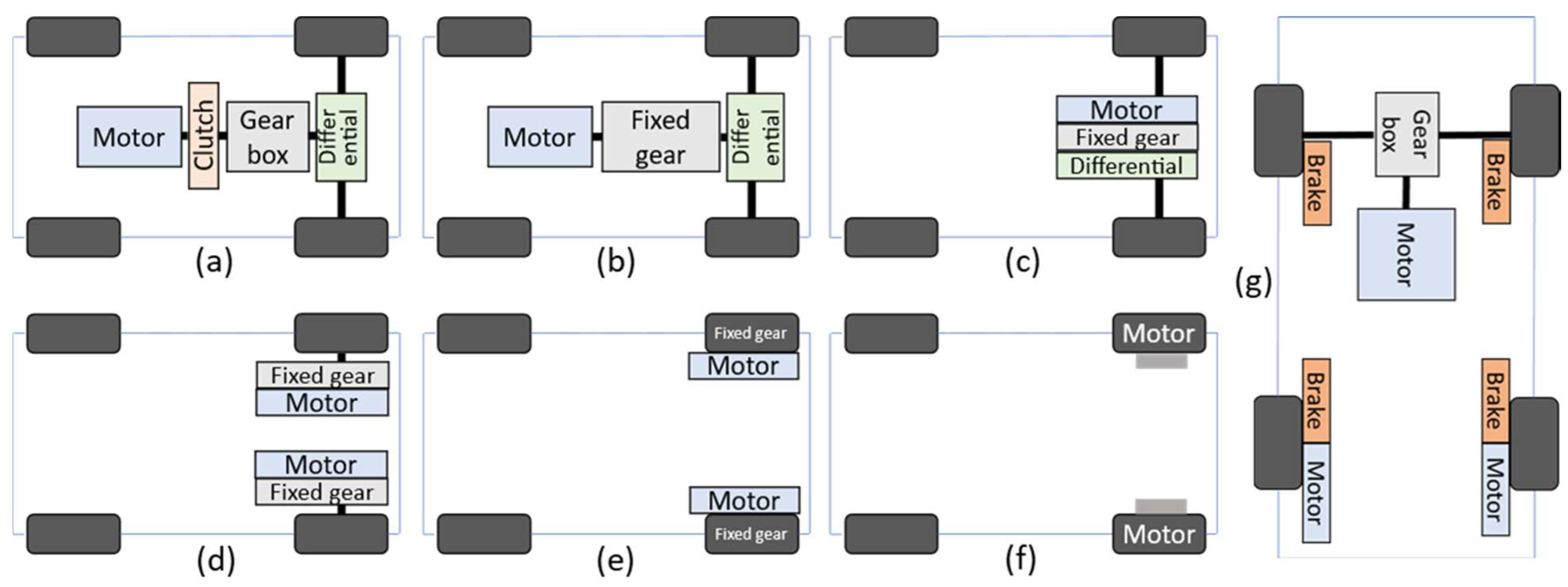
The four primary functions in a vehicle are traction, braking, steering and suspension. With vehicle electrification the mechanical actuators performing these functions are replaced by electric drives, thus, the vehicle becomes a system with multiple motors, and a multi-motor drive architecture may be beneficial. From another and more important aspect, due to the typical layout of a vehicle (two axles comprising two wheels each), each of these systems can be divided into sub-systems with a separate electric drive for each sub-system. This extends the operation domain of the system and allows for advanced technologies to be implemented. There are also cases where a modular approach is adopted where each motor is divided into multiple segments, either to enhance the performance or achieve fault tolerance. In both cases, each system (or sub-system) in the vehicle becomes a multi-motor system, and in each system the electric drives can have the same characteristics and perform the same functions, which further supports a multi-motor drive architecture design approach. In the following, examples from commercial vehicles and research portraying the prevalence of multi-motor systems in vehicular systems are presented. The examples are classified based on the vehicular function and other examples are presented separately.
2. Traction
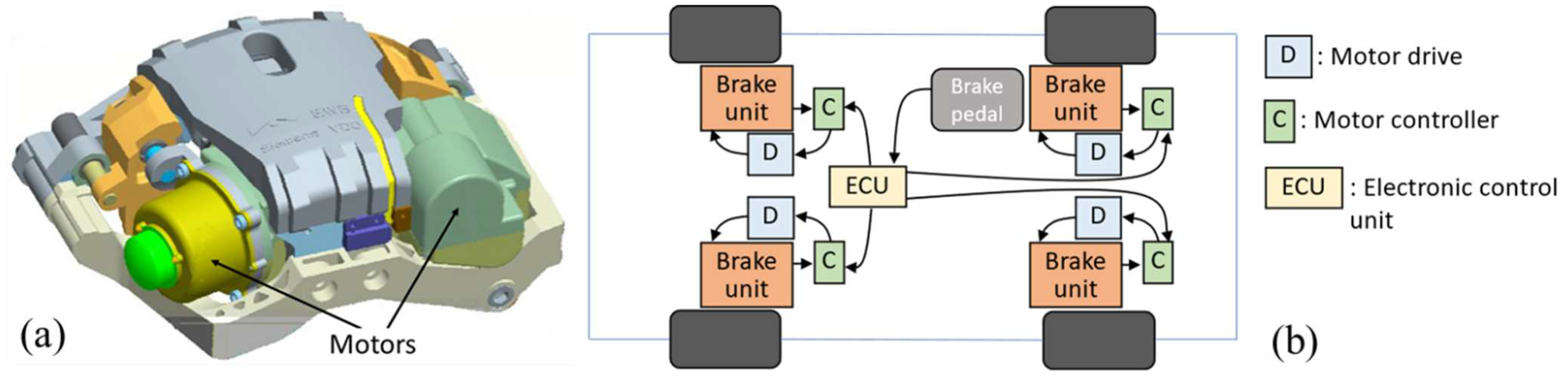
3. Braking
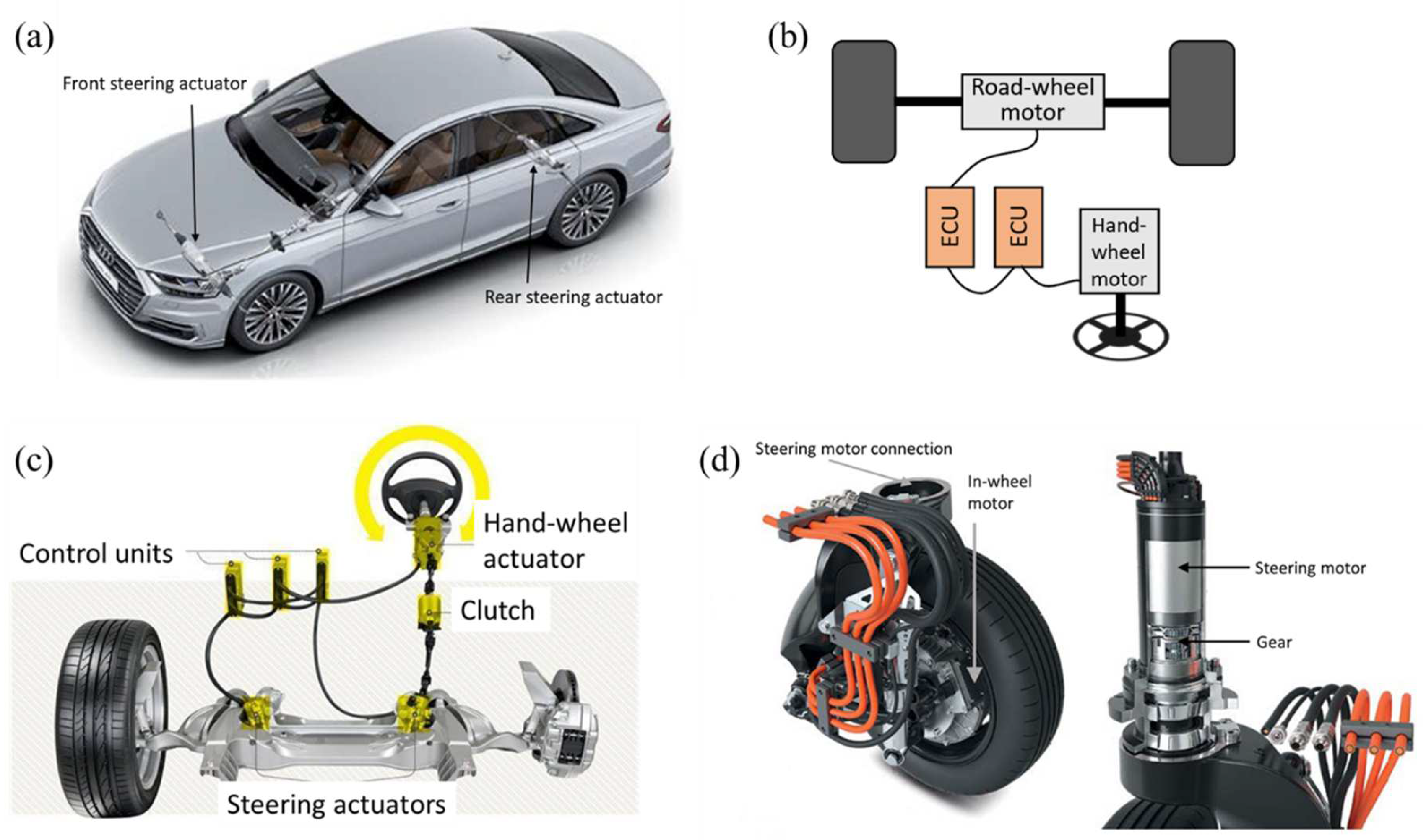
4. Steering
5. Suspension

6. Other Examples
References
- Cai, W.; Wu, X.; Zhou, M.; Liang, Y.; Wang, Y. Review and Development of Electric Motor Systems and Electric Powertrains for New Energy Vehicles. Automot. Innov. 2021, 4, 3–22.
- Chan, C. The state of the art of electric and hybrid vehicles. Proc. IEEE 2002, 90, 247–275.
- Kang, J.; Kyongsu, Y.; Heo, H. Control Allocation based Optimal Torque Vectoring for 4WD Electric Vehicle. In Proceedings of the SAE 2012 World Congress & Exhibition, Detroit, MI, USA, 24–26 April 2012.
- Audi Drive Concept for E-Tron S-Models: Three Motors, New Quattro Generation with Electric Torque Vectoring—Green Car Congress. 6 March 2020. Available online: https://www.greencarcongress.com/2020/03/20200306-audi.html (accessed on 25 July 2022).
- Gruber, P.; Sorniotti, A.; Lenzo, B.; Filippis, G.D.; Fallah, S. Energy efficient torque vectoring control. In Proceedings of the 13th International Symposium on Advanced Vehicle Control, Munich, Germany, 13–16 September 2016.
- Jalali, K. Stability Control of Electric Vehicles with In-Wheel Motors. Ph.D. Thesis, University of Waterloo, Waterloo, ON, Canada, 2010.
- Fox, J.; Roberts, R.; Baier-Welt, C.; Ho, L.M.; Lacraru, L.; Gombert, B. Modeling and Control of a Single Motor Electronic Wedge Brake. In Proceedings of the SAE World Congress & Exhibition, Detroit, MI, USA, 16–19 April 2007.
- CLEPA. UN R.13 and Electro Mechanical Brakes; United Nations Economic Commission for Europe (UNECE): Geneva, Switzerland, 2020; Available online: https://unece.org (accessed on 25 July 2022).
- Seglö, F. A System with a Future: Electro Mechanical Brake (EMB) from Haldex. Haldex Magazine, 8 April 2018.
- Gong, X.; Ge, W.; Yan, J.; Zhang, Y.; Gongye, X. Review on the Development, Control Method and Application Prospect of Brake-by-Wire Actuator. Actuators 2020, 9, 15.
- SMortazavizadeh, S.A.; Ghaderi, A.; Ebrahimi, M.; Hajian, M. Recent Developments in the Vehicle Steer-by-Wire System. IEEE Trans. Transp. Electrif. 2020, 6, 1226–1235.
- Audi A8 Features New Dynamic All-Wheel Steering, AI Active Suspension—Green Car Congress. 17 July 2017. Available online: https://www.greencarcongress.com/2017/07/20170717-a8.html (accessed on 25 July 2022).
- He, L.; Chen, G.Y.; Zheng, H.Y. Fault tolerant control method of dual steering actuator motors for steer-by-wire system. Int. J. Automot. Technol. 2015, 16, 977–987.
- Chunduri, P. Have you ever wondered what is ‘Drive-by-wire’ or ‘x-by-wire’? WordPress.com. 10 February 2017. Available online: https://mymotorwheels.wordpress.com/2017/02/10/have-you-ever-wondered-what-is-drive-by-wire-or-x-by-wire/ (accessed on 25 July 2022).
- Eckstein, L. Future Trends for Automotive Steering Systems. JTEKT Eng. J. 2016, 1013E.
- Harkort, C.; Kesselgruber, D.; Kraus, M.; Moseberg, J.; Wuebbolt-Gorbatenko, B. Mobile in the City of Tomorrow the Fusion of Drive and Chassis. In Proceedings of the Schaeffler Symposium, Baden-Baden, Germany, 11–13 April 2018.
- Xue, X.D.; Cheng, K.W.E.; Zhang, Z.; Lin, J.K.; Wang, D.H.; Bao, Y.J.; Wong, M.K.; Cheung, N. Study of art of automotive active suspensions. In Proceedings of the 4th International Conference on Power Electronics Systems and Applications, Hong Kong, China, 8–10 June 2011.
- Cytrynski, S.; Neerpasch, U.; Bellmann, R.; Danner, B. The Active Suspension of the New Mercedes-Benz GLE. ATZ Worldw. 2018, 120, 42–45.
- Grillneder, S. Multifaceted Personality: Predictive Active Suspension in the A8 Flagship Model—Audi MediaCenter. 2019. Available online: https://www.audi-mediacenter.com/en/press-releases/multifaceted-personality-predictive-active-suspension-in-the-a8-flagship-model-11905 (accessed on 25 July 2022).
- Michelin Active Wheel. 2008. Available online: http://www.climatebabes.com/documents/DP_Mondial08_MichelinActiveWheel-EN.pdf (accessed on 25 July 2022).
- Cars Explained. Requests: Bose Suspension System. Wordpress.com. 2018. Available online: https://carsexplained.wordpress.com/2018/06/23/requests-bose-suspension-system/ (accessed on 25 July 2022).
- Gysen, B.L.J. Generalized Harmonic Modeling Technique for 2D Electromagnetic Problems. Ph.D. Thesis, Technische Universiteit Eindhoven, Eindhoven, The Netherlands, 2011.
- Ruiz, R. High Performance Electromechanical Actuator for Active Rear Axle Kinematics of a Sports Car. SAE Int. J. Passeng. Cars Electron. Electr. Syst. 2012, 5, 528–540.
- Salem, A.; Narimani, M. A Review on Multiphase Drives for Automotive Traction Applications. IEEE Trans. Transp. Electrif. 2019, 5, 1329–1348.
- Li, K.; Bouscayrol, A.; Han, S.; Cui, S. Comparisons of Electric Vehicles Using Modular Cascade Machines System and Classical Single Drive Electric Machine. IEEE Trans. Veh. Technol. 2017, 67, 354–361.
- Li, K.; Bouscayrol, A.; Cui, S.; Cheng, Y. A Hybrid Modular Cascade Machines System for Electric Vehicles Using Induction Machine and Permanent Magnet Synchronous Machine. IEEE Trans. Veh. Technol. 2020, 70, 273–281.
- Xu, X.; Liang, J.; Hao, Q.; Dong, P.; Wang, S.; Guo, W.; Liu, Y.; Lu, Z.; Geng, J.; Yan, B. A Novel Electric Dual Motor Transmission for Heavy Commercial Vehicles. Automot. Innov. 2021, 4, 34–43.
- Yang, H.; Jian, Z.; Xuhui, W. High Power Dual Motor Drive System Used in Fuel Cell Vehicles. In Proceedings of the IEEE Vehicle Power and Propulsion Conference (VPPC), Harbin, China, 3–5 September 2008.
- Kostic Perovic, D. Making the Impossible, Possible—Overcoming the Design Challenges of in Wheel Motors. World Electr. Veh. J. 2012, 5, 514–519.