Your browser does not fully support modern features. Please upgrade for a smoother experience.
Please note this is a comparison between Version 2 by Rita Xu and Version 1 by Abdulaziz A Alturki.
Carbon dioxide is a byproduct of our industrial society. It is released into the atmosphere, which has an adverse effect on the environment. Carbon dioxide management is necessary to limit the global average temperature increase to 1.5 degrees Celsius and mitigate the effects of climate change, as outlined in the Paris Agreement.
Carbon dioxide is a byproduct of the industrial society. It is released into the atmosphere, which has an adverse effect on the environment. Carbon dioxide management is necessary to limit the global average temperature increase to 1.5 degrees Celsius and mitigate the effects of climate change, as outlined in the Paris Agreement.
- CO2 emissions
- CO2 mineralization
1. Introduction
CO2 emissions from industries that use fossil fuels can be a significant cause of CO2 accumulation in the atmosphere. More than 36 Gt of CO2 is emitted globally per year from fossil fuel combustion, cement production, and other industrial processes. Between 1975 and 2018, atmospheric CO2 levels dramatically increased from 250 ppm to 410 ppm [1,2][1][2]. Comparatively, this increase was 48% greater than records from the previous two decades; however, even these two decades demonstrated a 39% increase in CO2 levels, resulting in a 0.8 °C rise in the global surface temperature [2,3][2][3]. Continuous improvements in CO2 mitigation stabilized the global annual CO2 emissions between 2014 and 2017; however, data obtained between 2018 and 2019 suggested an annual 2.7% and 0.6% increase, respectively. These data predict CO2 emissions to increase further in the coming years [4]. In the absence of any climate sustainability policies, using 2000 as a baseline, a 25–90% increase of global greenhouse gases (GHG) emissions is expected by 2030. The growth in atmospheric CO2-equivalent concentrations for this estimate is considered to be as much as 600–1550 ppm [5]. Different fuel sources contribute in different ways to the emission of CO2, though typically emissions are the result of energy and industrial production. The contributing fuels include gas, liquid (i.e., oil), solids (coal and biomass), flaring, and cement production [4,6][4][6]. The global energy-related CO2 emissions increased in 2018 to 33.1 Gt of CO2, indicating a 1.7% rise in emissions. Eighty-five percent of the net increase was attributed to China, India, and the United States’ emissions, mainly from using coal in power generation. For Asia, the emission levels surpassed 10 Gt of CO2 [7]. Besides coal, other fossil fuels, including oil and gas, cause severe environmental concern [3]. CO2 emissions are the main cause of climate change and increased global warming, creating many global issues. This concern has triggered the international research community to examine how best to reduce the concentration of CO2 in the atmosphere [3,4,5,6,7][3][4][5][6][7]. Various countries have considered and adopted different approaches. These approaches include:
-
Improve and promote energy conservation and efficiency
-
Use fuels with low carbon output, such as nuclear, hydrogen, natural gas, etc.
-
Set up solar, hydropower, wind, and bioenergy as renewable energy sources (RES)
-
Promote carbon capture and storage (CCS)
To reduce CO2 emissions, a variety of mitigation strategies have been developed [1,4][1][4]. Among the technological alternatives for reducing the amount of CO2 emitted into the atmosphere are the following: (a) substituting less carbon-intensive fuels, such as natural gas, for coal; (b) increasing the use of RES or nuclear energy, both of which emit little or no net CO2; and (c) capturing and sequestering CO2. This aentrticley will examine the third option, CO2 capture and sequestration (CCS), as a cost-effective strategy for mitigating climate destabilization caused by high levels of energy-related CO2 emissions [8]. Table 1 (below) compares the strategy, areas of application, advantages, and limitations for the reduction of CO2 emissions using different approaches. Some of the approaches deal with reducing the sources that CO2 comes from, such as using clean technologies or clean fuel. Others use demand-side management, for example, energy conservation for source emissions reduction. Depending upon the applicability, each approach has its advantages and limitations under specific conditions. Furthermore, a single strategy or approach is unlikely to be adequate enough to meet the Intergovernmental Panel on Climate Change (IPCC) goals for CO2 emissions [3]. These include the goal of a 50–85% reduction by 2050 as compared to levels in 2000. To maintain the rise in Earth’s temperature below 1.5 °C, the IPCC has emphasized achieving the Paris Agreement climate targets by 2030. Clean hydrocarbon technologies (CHTs) can play a crucial role in meeting the demands of a circular carbon economy. The CHTs result in a minimal carbon footprint while converting hydrocarbons’ energy into electricity, fuel, or other valuable mechanical work [9]. Newer conversion technologies are under development and are being researched for meeting climatic targets while realizing energy transitions, including direct hydrocarbon fuel cells, conversion of CO2 into fuels, and underground gasification of hydrocarbons in combination with CCS to enable a cost-effective global circular carbon economy (CCE) [9].
| Strategy | Application Area | Advantages | Limitations | |||
|---|---|---|---|---|---|---|
| Enhance efficiency and conservation of energy | Mainly used in industrial and commercial buildings. | 10% to 20% energy saving. | Extensive investment in installation. | |||
| Use renewable energy | Solar (thermal), hydro, and wind power. | Uses local natural resources; no toxic gas emissions. | Intermittent energy generation limitations open spatial and temporal gaps between the availability of the energy and its consumption by the end-users. | |||
| Increase clean fuels usage | Substitute natural gas with coal. | Natural gas has lower carbon content and w.r.t. compared to coal. Emits 40–50% less carbon dioxide. Has higher combustion efficiency. | More costly than conventional natural gas. | |||
| Adaptation of clean coal technologies | Replace conventional combustion through pressurized fluidized bed combustor, integrated gasification combined cycle (IGCC), etc. | Use of coal with lower CO | 2 | emissions. | Significant investment is needed. | |
| Afforestation and reforestation | Applicability in all countries. | Approach to create natural and sustainable sinks of CO | 2 | . | Restricts the use of land for other applications. | |
| Nuclear power development | Nuclear fission was adopted mainly in France, Russia, the US, Japan, and China. It is still in the developmental phase. |
No greenhouse gas and air pollutant emissions. | Controversial to use. Hindered due to the nuclear accident at Fukushima in 2011. | |||
| CCS (Carbon capture and storage) | Applicability to significant emission sources of CO | 2 | Its capture efficiency can reduce CO | 2 | emissions by >80%. | Technologies of CCS are not commercially approved. |
Implementing the CCE recommended clean energy transitions can be accomplished by promoting the ‘4Rs’ [10][11]. The first ‘R’ stands for reduce, which involves using energy efficiency and other alternative energy sources such as renewable or nuclear energy to reduce the amount of carbon entering the atmosphere. The second stands for reuse, which involves capturing and converting carbon into valuable industrial feedstock or increasing productivity by re-injecting carbon back into oil and gas reservoirs. The third stands for recycling, which consists of producing fertilizer, cement, or other valuable fuels through natural processes used for carbon transformation. Finally, the last ‘R’ stands for remove, which involves geological and chemical carbon removal from the system [11][12].
A stepwise closure of the carbon cycle through utilization and conversion of carbon is involved in the CCE, which significantly reduces carbon emissions. Many of the CHTs which are needed for CCE are still under development [9]. The integration of carbon capture and utilization (CCUS) into existing power plants and the increase in its implementation is expected to lower the electricity consumption costs to $50/ton in 2050 [12][13]. However, the CCUS technology is still being researched for cost-reduction and developed for improved energy needs and capture efficiency. Based on the CO2 capture and production process used in CCUS, its projects can be categorized as carbon positive, carbon-neutral, or carbon negative. To ensure sustainable utilization of hydrocarbons, the carbon-neutral and carbon-negative CCUS projects are required [9].
The direct capture of carbon dioxide from air using absorbent technologies or biomass combustions is performed in negative CO2 capture technologies, whose economic viability can be enhanced by producing high-value chemical products from captured CO2. Gasification of hydrocarbons is another promising commercially demonstrated technology that involves producing high-value gaseous products from heavy low-value feedstock, thus improving the cost efficiency of the system. However, this technology is still being developed for underground implementation [13][14].
The solid oxide fuel cell (SOFC) system is considered the most efficient for producing clean power. Theoretically, an efficiency of 90% is recorded for SOFCs when combined with underground gasification or carbon capture systems. Thermal splitting technology is also used for clean hydrogen production, which competes with electrochemical, photo-chemical, and photo-biological routes utilizing solar energy for clean hydrogen production [14][15]. The latter provides the heat for the production process through concentrated solar radiation, and the combustion or fuel cells are used to generate electricity from the produced hydrogen. However, unlike nuclear, photo-biological, or photo-chemical routes, thermal splitting does not require the construction of new plants, as it can utilize the existing conventional facilities with modifications [9].
Mineralization of carbon, known alternatively as mineral carbonation or CO2 mineral sequestration, is an emerging approach used for carbon dioxide (CO2) removal and storage. Although government agencies generally adopt a piecewise approach to CO2 management, long-term solutions typically involve the underground injection of CO2. This solution, however, involves substantial risk and cost. An alternative to traditional geological sequestration is carbon mineralization, in which CO2 is reacted to form carbonate minerals with metal cations such as magnesium, calcium, and iron. This storage is mainly performed in carbonate minerals, e.g., calcite or magnesite. The solid inorganic carbonates, which are thermodynamically more stable, are provided as an alternative by mineral carbonation to the underground storage of gaseous carbon dioxide [2]. Industrial or large-scale CO2 utilization or recycling can result in large-scale production of carbon dioxide products that can be sold to different industries and thus help improve the economic viability of such processes. Calcium carbonate products can potentially be produced using Ca-based CO2 mineralization processes. These products can find application in industries requiring precipitated calcium carbonates, e.g., paper and cement, or landfill storage options. For example, cement clinkers and road construction aggregates require calcium carbonate [15][16]. Carbon dioxide products obtained from different technologies have two separate applications. These include low-end high-volume uses and high-end low-volume uses. However, these products should fulfill certain specifications and quality criteria of commercial value [16][17]. Diverse industrial applications are currently recorded for carbonate minerals, finding use in construction, paper and pulp, the pharmaceutical industry, and applications in the agricultural sector and refractory metals [17][18]. Potential markets have been explored for inorganic and organic carbonates obtained from carbon mineralization. These products include CaCO3, MgCO3, NaCO3, KCO3, polycarbonate, dimethyl/ethyl carbonates, etc. [15,16,17][16][17][18].
The construction industry offers the most suitable application opportunities for mineral carbonates concerning overall CO2 emission avoidance [17][18]. Crushed stone construction aggregates present the largest conventional carbonate market, with a 22.5 Gt global demand for carbonate materials such as limestone and dolomite [16][17].
The low-end high-volume uses of mineral carbonate products include liming agents in soil acidity treatment, silica, magnesium, and calcium carbonates for land reclamation and mine reclamation, etc. The high-end product applications call for strict specifications. Other applications include catalysts, chromatography, ceramics, pigments, pharmacy, photographic emulsions, etc. Moreover, other novel functional usages of calcium carbonate include plastics, rubber, paint, printing ink, weaving, toothpaste, make-up, and foodstuffs. Different polymorphic forms of CaCO3 can improve paint dispersion, plastic reinforcement, and ink transparency. However, these applications require a high level of purity, which demands additional post-processing of these products [16][17].
2. Current Industrial Technologies to Mitigate CO2 Emissions
CCS is an auspicious method of reducing GHG emissions by capturing CO2 at the power plant, transporting it to an injection site, and sequestering it in suitable formations for long-term storage. By installing a CCS unit at thermoelectric plants, approximately 85–95% of CO2 processed in a capture plant can be captured efficiently. CO2 capture technologies have been introduced, but they are costly. They typically make up 70–80% of the total cost of an entire CCS system, including various technological processes such as separate capture and storage, etc. [19,20][19][20]. Various R&D groups are working to develop a cheaper operating system with less energy penalties. The CCS process consists of three major components: capturing CO2 produced by fossil fuel combustion, transporting CO2 to the storage site, and storing CO2 for an extended period of time rather than releasing it into the atmosphere. Four primary CO2 capture processes are linked to combustion processes, which are post-combustion, pre-combustion, oxy-fuel combustion, and chemical looping combustion, as illustrated in Table 2 [3].Table 2. Comparison of Four Capture Processes [3,27,31,50,51,52,53,54][3][21][22][23][24][25][26][27].
| Capture Process | Application Sector | Advantages | Disadvantages | Energy Required (MWh/t-CO | 2 | ) | Carbon Footprint (kgCO | 2 | eq/MWh) | ||
|---|---|---|---|---|---|---|---|---|---|---|---|
| Post-combustion | Gas-fired and coal-fired plants | More mature technology; easily retrofit into existing plants | Capture efficiency can be affected by low CO | 2 | concentration | 0.50 [50] | 0.50 [23] | - | |||
| Pre-combustion | Plant of coal gasification | High CO | 2 | concentration enhances efficiency; fully developed technology, commercially deployed, and can be retrofitted into existing plants | Heat transfer and efficiency decay problems associated with turbine fuel, such as using hydrogen-rich gas; high operational cost; and parasitic power requirement for sorbent regeneration | 2.6–3.0 [51] | 2.6–3.0 [24] | 150 [31] | 150 [22] | ||
| Oxy-fuel combustion | Coal-fired and gas-fired plants | A high concentration of CO | 2 | enhances absorption efficiency; mature air separation technologies are also available | Drop-in efficiency and energy penalty; costly O | 2 | production; and the problem of corrosion may arise | 0.10–0.50 [52] | 0.10–0.50 [25] | 110–120 [27,31] | 110–120 [21][22] |
| Chemical looping combustion | Coal-gasification plants | CO | 2 | , the main combustion product, remains unaltered with N | 2 | to avoid air separation | A process under development and inadequate for large scale operation | 1.30 [53] | 1.30 [26] | 65–69 [31,54] | 65–69 [22][27] |
Regarding the application of low-carbon technology, the Energy Sector is undergoing a rapid technological transformation. Consequently, conventional gas turbines and internal combustion engines will probably need to be incorporated into systems utilizing biofuels and/or CCUS. Also, the European Union is moving quickly toward low-carbon technologies (such as energy efficiency, Smart Grids, renewables, and CCUS), as seen by the Energy Union Strategy [27][21]. A viable method for efficiently capturing carbon dioxide emissions generated by natural gas burning in the combustion chamber could be implementing improved combustion technology. When it comes to a combined cycle (CC) powered entirely by hydrogen, this is a new technology that is expected to hit the market in the coming years; one example is Vattenfall’s Magnum natural gas-fired gas turbine combined cycle (GTCC) plant (440 MW) in the Netherlands, which will be converted from natural gas to hydrogen by Mitsubishi Hitachi Power Systems (MHPS) in 2025 [28][34]. From 2010 to 2018, the Fusina power station in Italy was powered by hydrogen (16 MW, estimated efficiency of 43 percent, GE10-1 type, single shaft, eleven compressor stages, three turbine stages) [28][34]. More than 75 GE gas turbines have accumulated more than 5 million working hours using hydrogen-based fuels. An A-Frame 6B unit at the Daesan petrochemical facility in Korea was constructed in 1997 and consistently runs with hydrogen concentrations between 85 and 97 percent [29][35]. It is an example of a hydrogen fleet leader. The HYFLEXPOWER is also moving towards this approach [30][36]. It uses hydrogen instead of natural gas (H2-CC) (a CC powered by hydrogen). The substitution of natural gas with hydrogen (H2-CC) reduces CO2 by 33% from natural gas combined cycle (NGCC), which consumes 450 to 150 kgCO2eq/MWh using hydrogen instead (Table 2) [31][22]. However, the gas turbines of the combined cycles must be somewhat updated, and the power plants require an infrastructure capable of providing hydrogen at a cost-effective rate. The production of hydrogen through power-to-gas technology represents a possibility. Because of this, the excess electricity from wind and solar PV is utilized to produce hydrogen via electrolyzers [31][22].
Instead of using air, oxygen is used in the combustion of the oxyfuel process. When pure oxygen is used in place of air for combustion, an oxy-fuel capture system produces a flue gas mixture primarily composed of CO2 and condensable water vapor, which can be separated and cleaned relatively easily during the compression process. This reduces the nitrogen production present in exhaust gas, hindering the separation process. Using pure oxygen is beneficial and results in the production of flue gases including CO2 and water. Additionally, SO2 and particulates are also produced. These can be removed via desulphurization and conventional electrostatic precipitator, respectively. Other gases produced also contain some CO2, depending on the fuel used. These can be separated, transported, and stored [32][37]. This process is more feasible, but the large consumption of oxygen results in a high loss and an energy penalty of 7% [3]. Moreover, system corrosion problems can be intensified with the high concentration of SO2. Many developmental oxy-fuel projects are currently operating and under further development. Some sub-scale oxy units are also under development, as CS energy and Vattenfall proposed [33][38]. Burning coal under these conditions produces a flue gas rich in CO2 (60–70 mol%) with substantial amounts of H2O (20–25 mol%), O2 (3–4 mol%), and N2 (0–10 mol%), which varies according to coal rank and process design. Using a gas processing unit (GPU), this flue gas is enhanced to transport criteria [34,35,36][39][40][41]. The oxyfuel coal CCS system can reduce the impact of global warming. However, the energy demand of the air separation unit (ASU) and CO2 compression unit in the oxyfuel CCS system necessitates an increase in fuel combustion per kilowatt-hour, hence increasing the chain-wide consequences. Due to the energy demand of the air separation unit, the use of oxyfuel combustion in a power plant reduces the facility’s net efficiency (ASU). Due to the energy allocation for ASU, the natural gas oxyfuel combustion system is projected to have an efficiency loss of 11.3% [31][22]. By upgrading NGCC to oxy-NGCC, 450 can be lowered to 111 kgCO2eq/MWh (a reduction of 75%).
In chemical looping combustion (CLC), the metal oxide is used for combustion instead of pure oxygen, which is used in oxy-fuel combustion. The metal results from metal oxide, and fuel oxidation produces CO2 and water in this process. Metal is further oxidized and recycled; water (a by-product) is removed by condensation, while CO2 can be separated without consuming additional energy. Researchers found that using inert material can optimize the ability of metal oxide, but the inert material is specific for each metal oxide [33,37,38][38][42][43]. Moreover, the feasibility of this combustion in an experiment was studied, finding this technology to be promising for CO2 capture [39][44]. In comparison to IGCC using pre-combustion technology, the efficiency of chemical looping is 2.8% higher [40][45]. CLC has unrealized potential for use in power generation systems with zero CO2 emissions. CLC technology can compete with other pro-CCS technologies, such as oxy-fuel combustion, pre-combustion capture, and post-combustion capture, due to the inherent separation in CLC reactors, which drastically reduces the internal load of the plant. However, it is not yet mature enough to be implemented commercially [41][46]. The combination of CLC and gas turbines (GT)s can reduce a CC power plant’s efficiency from 60% to around 40% [42][47]. To maintain the same level of energy output, more natural gas will need to be used. This type of plant’s investment expenses is also anticipated to rise. It is estimated that the combustion chamber accounts for 11% of the total turbine expenditure [43][48] and that a pressurized fluidized bed combustor can cost between 2140 and 5700 $/kW [44][49]. Based on these economic numbers, a comprehensive financial analysis of the required investment for a standard CC power plant and a CC power plant with CLC was undertaken. Studies using sensitivity analysis were performed on the carbon credit price to determine at what price the investment becomes attractive [31][22]. In addition, a comprehensive analysis of the life cycle of the two power plants was conducted to determine whether the loss of efficiency of the plant employing the chemical looping combustor impacts environmental performance. Fan et al. conducted an intriguing Life Cycle Assessment (LCA) on CLC plants coupled to CC fueled by natural gas. They evaluated the influence of four technical aspects on the ultimate impact: the type of oxygen carrier, its lifespan, the environmental impact caused by its production, and the thermodynamic performance of the technology. The environmental impact is highly dependent on the thermodynamic efficiency of the plant. Thus, it is preferable to use a CC with a pressurized CLC reactor instead of an atmospheric reactor, which can only be coupled to a steam turbine and has lower efficiency. In addition, the duration of the oxygen carrier has a significant impact on the plant’s environmental impact. The oxygen carrier is concerned with attrition and reactivity losses. An NGCC plant emits around 450 kgCO2eq per megawatt-hour of power produced. Upgrading NGCC to CLC-NGCC can reduce emissions by 422 MtCO2 (a reduction of 49%) [31][22].
The utilization of CO2 in CCS is more feasible for high-concentration point sources (12–15%) such as power plants and cement industries, while in small-concentration sources of CO2 emissions such as those being removed from transportation, it is less likely to be feasible. CO2 capture from flow gas has been implemented in multiple natural gas processing industries and existing power plants. The ability of this strategy to be retrofitted to existing power plants and other industries makes it superior to prior combustion of CO2. The CO2 content ranges from 3 to 15%, the lower end of this range (3–5%) being typical for gas-fired plants and the upper end (12–15%) for coal-fired plants. The CO2 emissions from steel production typically amount to ~1.4 t-CO2/t-steel. Oil refineries accounted for ~3% of global emissions with a total of ~0.9 Gt-CO2 emitted to the atmosphere in 2015 [45][50]. An IPCC analysis of large point sources identified 638 refineries emitting an average of 1.25 Mt-CO2/year [46][51]. Total global CO2 emissions from cement production amounted to ~2 Gt-CO2 and yielded a flue gas with CO2 of typically 14–33% with ~0.8 t-CO2/t-cement. Large fossil fuel power plants account for almost half of the total CO2 emissions from fossil fuel combustion. These large point sources emit nearly 26% of the total global fossil fuel and industry emissions. Modern technologies, such as coal-fired, oil-fired, and combined cycle gas turbine (CCGT) power plants, are primarily responsible for most of the CO2 emissions from the power sector. Depending on the fossil fuel composition and lower heating value (LHV), CO2 emissions are assessed. The greater the percentage of fuel, the greater the CO2 emissions. Considering lower heating value (LHV) and CO2 emission levels, the increasing proportion of H2 gives fossil fuels better properties. Natural gas consists primarily of CH4 and has nearly two times fewer emissions than hard and lignite coal as well as an almost two-times greater LHV. This fact is based on the composition of gas fuels, in which each methane molecule contains four hydrogen atoms for every carbon atom [47][52].
Other contemporary power generation methods, such as nuclear, RES, and hydrogen-based methods, are less likely to produce emissions [48][53]. Without carbon capture, a newly constructed CCGT power plant emits 350 kgCO2/MWh of CO2, which is the same as a gas-fired power plant. In the case of a coal-fired ultra-supercritical power plant, CO2 emissions of up to 700 kgCO2/MWh are possible. CO2 emissions range between 690 and 820 kgCO2/MWh, depending on the type of coal-fired critical power plant used [49][54]. Modern energy technology will continue to use fossil fuels until they are replaced by alternative technologies, such as renewable energies and emission-free power production. CO2 capture is required to reduce greenhouse gases and protect the environment until these technologies can be replaced with those that do not emit CO2.
After CO2 is captured, it is compressed to create a supercritical fluid with properties intermediate between a gas and a liquid. It is then transported to a long-term storage location. When selecting CO2 storage sites, several factors are typically considered: the volume, purity, and rate of the CO2 stream; the proximity of the source and storage sites; the infrastructure for CO2 capture and delivery; the presence of groundwater resources; and the storage site’s safety [55,56][55][56]. There are several options for CO2 storage, including injecting it into the ocean and allowing it to sink to the bottom or, more commonly, using geological formations as natural reservoirs, in which wells are drilled and CO2 is injected to depths greater than 1 km. Carbon sequestration is the long-term storage of carbon in soils, plants, oceans, and geologic formations which occurs spontaneously and due to anthropogenic activities. It refers to the storage of carbon, which can become CO2. Due to climate change, carbon sequestration has been increasing in response to increased CO2 in the atmosphere. Changes in the land, forestry, and CCS techniques can increase carbon sequestration for the long-term storage of carbon [57]. Gas reservoirs and depleted oils, un-minable coal seams, deep saline formations, and enhanced oil recovery operation formations are the geological sinks of CO2. Together with the help of different physical and mechanical trapping mechanisms, carbon sequestration can store thousands of GtC (gigatons of carbon) [58]. Geological storage is considered the most reliable way of storing a large quantity of CO2 to reduce the increasing global warming [59,60,61][59][60][61]. The site for geological storage of CO2 should be suitable, with appropriate porosity and a stable geological environment [61]. Table 3 shows the potential CO2 storage capacity of worldwide reservoirs for the sequestration sources as illustrated by Figure 1.
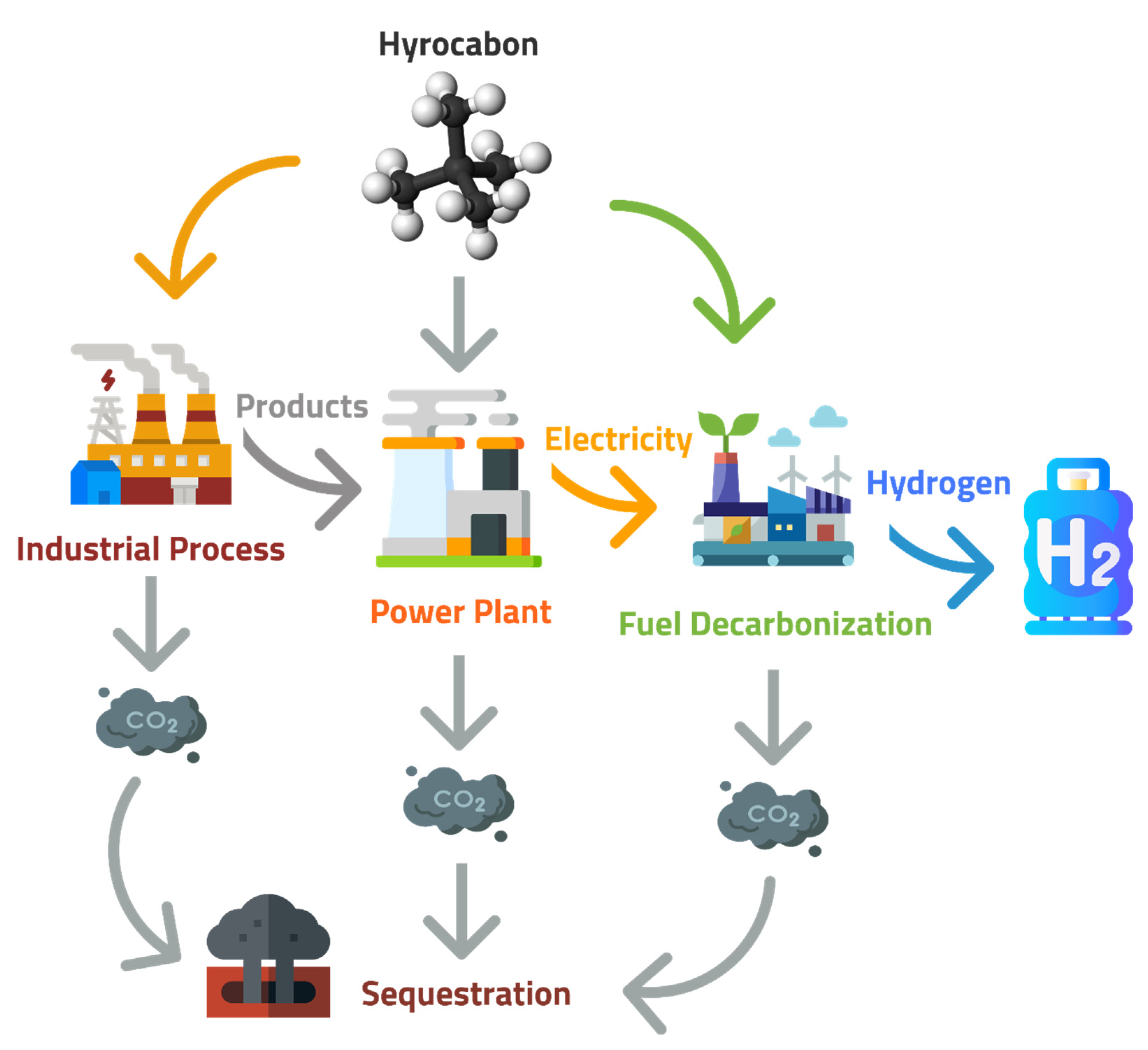
Figure 1. Sequestration sources of CO2 captured from power plants are a byproduct of industry or decarbonization plants.
Table 3. The potential CO2 storage capacity of worldwide reservoirs, reprinted with permission from Ref. [58]. Copyright 2022 Elsevier.
| Sequestration Option | Worldwide Capacity (Gt C) |
|---|---|
| Depleted Oil and Gas Reservoirs | 100–1000 |
| Deep Saline Formations | 100–10,000 |
| Ocean | 1000–10,000+ |
| Terrestrial | 10–100 |
| Coal Seams | 10–1000 |
References
- Pachauri, R.K.; Allen, M.R.; Barros, V.R.; Broome, J.; Cramer, W.; Christ, R.; Church, J.A.; Clarke, L.; Dahe, Q.; Dasgupta, P. Climate Change 2014: Synthesis Report. Contribution of Working Groups I, II and III to the Fifth Assessment Report of the Intergovernmental Panel on Climate Change; IPCC: Geneva, Switzerland, 2014.
- Metz, B.; Davidson, O.; De Coninck, H.; Loos, M.; Meyer, L. IPCC Special Report on Carbon Dioxide Capture and Storage; Intergovernmental Panel on Climate Change: Geneva, Switzerland, 2005.
- Leung, D.Y.C.; Caramanna, G.; Maroto-Valer, M.M. An Overview of Current Status of Carbon Dioxide Capture and Storage Technologies. Renew. Sustain. Energy Rev. 2014, 39, 426–443.
- Ritchie, H.; Roser, M. CO2 and Greenhouse Gas Emissions. Our World Data 2020, 1.
- Nakicenovic, N.; Alcamo, J.; Davis, G.; de Vries, B.; Fenhann, J.; Gaffin, S.; Gregory, K.; Grubler, A.; Jung, T.Y.; Kram, T. Special Report on Emissions Scenarios; Lawrence Berkeley National Laboratory: Berkeley, CA, USA, 2000.
- Yang, H.; Xu, Z.; Fan, M.; Gupta, R.; Slimane, R.B.; Bland, A.E.; Wright, I. Progress in Carbon Dioxide Separation and Capture: A Review. J. Environ. Sci. 2008, 20, 14–27.
- IEA. CO2 Status Report; IEA International Energy Agency: Paris, France, 2019.
- Mach, K.; Mastrandrea, M. Climate Change 2014: Impacts, Adaptation, and Vulnerability; Cambridge University Press: Cambridge, UK; New York, NY, USA, 2014; Volume 1.
- Alshammari, Y.M. Achieving Climate Targets via the Circular Carbon Economy: The Case of Saudi Arabia. C—J. Carbon Res. 2020, 6, 54.
- De Oliveira Costa Souza Rosa, C.; da Silva Christo, E.; Costa, K.A.; dos Santos, L. Assessing Complementarity and Optimising the Combination of Intermittent Renewable Energy Sources Using Ground Measurements. J. Clean. Prod. 2020, 258, 120946.
- Mansouri, N.Y.; Alma, A.; Al-Saud, N.T.; Alshalan, M.S.; Benlahrech, M.; Kobayashi, Y.; Sedaou, R.; Toyoda, M.; Yaroshenko, L. A carbon management system of innovation: Towards a circular carbon economy. G20 Insights 2020, 10, 12.
- Alatawi, H.; Darandary, A. The Saudi Move into Hydrogen: A Paradigm Shift; Instant Insight; King Abdullah Petroleum Studies and Research Center (KAPSARC): Riyadh, Saudi Arabia, 2020.
- Herzog, H.J. What Future for Carbon Capture and Sequestration? Environ. Sci. Technol. 2001, 35, 148A–153A.
- Alshammari, Y.M.; Hellgardt, K. A New HYSYS Model for Underground Gasification of Hydrocarbons under Hydrothermal Conditions. Int. J. Hydrogen Energy 2014, 39, 12648–12656.
- Romanov, V.; Soong, Y.; Carney, C.; Rush, G.E.; Nielsen, B.; O’Connor, W. Mineralization of Carbon Dioxide: A Literature Review. ChemBioEng Rev. 2015, 2, 231–256.
- Wang, F.; Deng, S.; Zhang, H.; Wang, J.; Zhao, J.; Miao, H.; Yan, J. A comprehensive review on high-temperature fuel cells with carbon capture. Appl. Energy 2020, 275, 115342.
- Sanna, A.; Uibu, M.; Caramanna, G.; Kuusik, R.; Maroto-Valer, M.M. A Review of Mineral Carbonation Technologies to Sequester CO2. Chem. Soc. Rev. 2014, 43, 8049–8080.
- Woodall, C.M.; McQueen, N.; Pilorgé, H.; Wilcox, J. Utilization of Mineral Carbonation Products: Current State and Potential. Greenh. Gases Sci. Technol. 2019, 9, 1096–1113.
- Blomen, E.; Hendriks, C.; Neele, F. Capture Technologies: Improvements and Promising Developments. Energy Procedia 2009, 1, 1505–1512.
- Davidson, R.M. Post-Combustion Carbon Capture from Coal Fired Plants-Solvent Scrubbing; IEA Clean Coal Centre: London, UK, 2007.
- European Environment Agency. COM 80 Final—A Framework Strategy for a Resilient Energy Union with a Forward-Looking Climate Change Policy. 2015. Available online: https://www.eea.europa.eu/policy-documents/com-2015-80-final (accessed on 21 May 2022).
- Bartocci, P.; Abad, A.; Cabello, A.; Zampilli, M.; Buia, G.; Serra, A.; Colantoni, S.; Taiana, A.; Bidini, G.; Fantozzi, F. Technical Economic and Environmental Analysis of Chemical Looping versus Oxyfuel Combustion for NGCC Power Plant. E3S Web Conf. 2021, 312, 08019.
- La Plante, E.C.; Simonetti, D.A.; Wang, J.; Al-Turki, A.; Chen, X.; Jassby, D.; Sant, G.N. Saline Water-Based Mineralization Pathway for Gigatonne-Scale CO2 Management. ACS Sustain. Chem. Eng. 2021, 9, 1073–1089.
- Rubin, E.S.; Davison, J.E.; Herzog, H.J. The Cost of CO2 Capture and Storage. Int. J. Greenh. Gas Control 2015, 40, 378–400.
- Huang, X.; Ai, N.; Li, L.; Jiang, Q.; Wang, Q.; Ren, J.; Wang, J. Simulation of CO2 Capture Process in Flue Gas from Oxy-Fuel Combustion Plant and Effects of Properties of Absorbent. Separations 2022, 9, 95.
- Khan, M.N.; Chiesa, P.; Cloete, S.; Amini, S. Integration of Chemical Looping Combustion for Cost-Effective CO2 Capture from State-of-the-Art Natural Gas Combined Cycles. Energy Convers. Manag. X 2020, 7, 100044.
- Fan, J.; Hong, H.; Jin, H. Power Generation Based on Chemical Looping Combustion: Will It Qualify to Reduce Greenhouse Gas Emissions from Life-Cycle Assessment? ACS Sustain. Chem. Eng. 2018, 6, 6730–6737.
- Ciferno, J.P.; Fout, T.E.; Jones, A.P.; Murphy, J.T. Capturing Carbon from Existing Coal-Fired Power Plants. Chem. Eng. Prog. 2009, 105, 33.
- Dincer, I.; Colpan, C.O.; Kizilkan, O. Exergetic, Energetic and Environmental Dimensions; Academic Press: Cambridge, MA, USA, 2017.
- De Visser, E.; Hendriks, C.; Barrio, M.; Mølnvik, M.J.; de Koeijer, G.; Liljemark, S.; Le Gallo, Y. Dynamis CO2 Quality Recommendations. Int. J. Greenh. Gas Control 2008, 2, 478–484.
- Olajire, A.A. CO2 Capture and Separation Technologies for End-of-Pipe Applications—A Review. Energy 2010, 35, 2610–2628.
- Kanniche, M.; Gros-Bonnivard, R.; Jaud, P.; Valle-Marcos, J.; Amann, J.M.; Bouallou, C. Pre-Combustion, Post-Combustion and Oxy-Combustion in Thermal Power Plant for CO2 Capture. Appl. Therm. Eng. 2010, 30, 53–62.
- Nord, L.O.; Anantharaman, R.; Bolland, O. Design and Off-Design Analyses of a Pre-Combustion CO2 Capture Process in a Natural Gas Combined Cycle Power Plant. Int. J. Greenh. Gas Control 2009, 3, 385–392.
- Mitsubishi Power. Available online: https://power.mhi.com/news/20180308.html (accessed on 21 May 2022).
- Fusina Combined Cycle Project: Planning to Run on Pure Hydrogen—Modern Power Systems. Available online: https://www.modernpowersystems.com/features/featurefusina-combined-cycle-project-planning-to-run-on-pure-hydrogen/ (accessed on 21 May 2022).
- Siemens, Engie, Euro Universities Create Hydrogen Gas Turbine Demonstrator Project. Available online: https://www.power-eng.com/gas/siemens-engie-euro-universities-create-hydrogen-gas-turbine-demonstrator-project/ (accessed on 21 May 2022).
- Buhre, B.J.P.; Elliott, L.K.; Sheng, C.D.; Gupta, R.P.; Wall, T.F. Oxy-Fuel Combustion Technology for Coal-Fired Power Generation. Prog. Energy Combust. Sci. 2005, 31, 283–307.
- Khila, Z.; Baccar, I.; Jemel, I.; Houas, A.; Hajjaji, N. Energetic, Exergetic and Environmental Life Cycle Assessment Analyses as Tools for Optimization of Hydrogen Production by Autothermal Reforming of Bioethanol. Int. J. Hydrogen Energy 2016, 41, 17723–17739.
- Cabral, R.P.; Heldebrant, D.J.; Mac Dowell, N. A Techno-Economic Analysis of a Novel Solvent-Based Oxycombustion CO2 Capture Process. Ind. Eng. Chem. Res. 2019, 58, 6604–6612.
- Kolster, C.; Mechleri, E.; Krevor, S.; Dowell, N.M. The Role of CO2 Purification and Transport Networks in Carbon Capture and Storage Cost Reduction. Int. J. Greenh. Gas Control 2017, 58, 127–141.
- Cabral, R.P.; Dowell, N.M. A Novel Methodological Approach for Achieving £/MWh Cost Reduction of CO2 Capture and Storage (CCS) Processes. Appl. Energy 2017, 205, 529–539.
- Li, F.; Luo, S.; Sun, Z.; Bao, X.; Fan, L.S. Role of Metal Oxide Support in Redox Reactions of Iron Oxide for Chemical Looping Applications: Experiments and Density Functional Theory Calculations. Energy Environ. Sci. 2011, 4, 3661–3667.
- Zafar, Q.; Mattisson, T.; Gevert, B. Integrated Hydrogen and Power Production with CO2 Capture Using Chemical-Looping Reforming Redox Reactivity of Particles of CuO, Mn2O3, NiO, and Fe2O3 Using SiO2 as a Support. Ind. Eng. Chem. Res. 2005, 44, 3485–3496.
- Adanez, J.; Abad, A.; Garcia-Labiano, F.; Gayan, P.; de Diego, L.F. Progress in Chemical-Looping Combustion and Reforming Technologies. Prog. Energy Combust. Sci. 2012, 38, 215–282.
- Erlach, B.; Schmidt, M.; Tsatsaronis, G. Comparison of Carbon Capture IGCC with Pre-Combustion Decarbonisation and with Chemical-Looping Combustion. Energy 2011, 36, 3804–3815.
- Czakiert, T.; Krzywanski, J.; Zylka, A.; Nowak, W. Chemical Looping Combustion: A Brief Overview. Energies 2022, 15, 1563.
- Zerobin, F.; Penthor, S.; Bertsch, O.; Pröll, T. Fluidized Bed Reactor Design Study for Pressurized Chemical Looping Combustion of Natural Gas. Powder Technol. 2017, 316, 569–577.
- Eret, P. A Cost-Effective Compressed Air Generation for Manufacturing Using Modified Microturbines. Appl. Therm. Eng. 2016, 107, 311–319.
- Timilsina, G.R. Are Renewable Energy Technologies Cost Competitive for Electricity Generation? Renew. Energy 2021, 180, 658–672.
- Liguori, S.; Wilcox, J. Design Considerations for Postcombustion CO2 Capture with Membranes. In Current Trends and Future Developments on (Bio-) Membranes; Chapter, 14; Basile, A., Favvas, E.P., Eds.; Elsevier: Amsterdam, The Netherlands, 2018; pp. 385–413.
- Wang, X.; Song, C. Carbon Capture from Flue Gas and the Atmosphere: A Perspective. Front. Energy Res. 2020, 8, 560849.
- Rackley, S. Overview of Carbon Capture and Storage. In Carbon Capture Storage; Elsevier: Amsterdam, The Netherlands, 2017; pp. 23–36.
- Madejski, P.; Chmiel, K.; Subramanian, N.; Kuś, T. Methods and Techniques for CO2 Capture: Review of Potential Solutions and Applications in Modern Energy Technologies. Energies 2022, 15, 887.
- Tramošljika, B.; Blecich, P.; Bonefačić, I.; Glažar, V. Advanced Ultra-Supercritical Coal-Fired Power Plant with Post-Combustion Carbon Capture: Analysis of Electricity Penalty and CO2 Emission Reduction. Sustainability 2021, 13, 801.
- Doughty, C.; Freifeld, B.M.; Trautz, R.C. Site Characterization for CO2 Geologic Storage and vice versa: The Frio Brine Pilot, TX, USA as a Case Study. Environ. Geol. 2008, 54, 1635–1656.
- Gibson-Poole, C.M.; Svendsen, L.; Underschultz, J.; Watson, M.N.; Ennis-King, J.; Van Ruth, P.J.; Nelson, E.J.; Daniel, R.F.; Cinar, Y. Site Characterisation of a Basin-Scale CO2 Geological Storage System: Gippsland Basin, Southeast Australia. Environ. Geol. 2008, 54, 1583–1606.
- Anwar, M.N.; Fayyaz, A.; Sohail, N.F.; Khokhar, M.F.; Baqar, M.; Khan, W.D.; Rasool, K.; Rehan, M.; Nizami, A.S. CO2 Capture and Storage: A Way forward for Sustainable Environment. J. Environ. Manag. 2018, 226, 131–144.
- Herzog, H.; Golomb, D. Carbon Capture and Storage from Fossil Fuel Use. Encycl. Energy 2004, 1, 277–287.
- Celia, M.A.; Nordbotten, J.M. Practical Modeling Approaches for Geological Storage of Carbon Dioxide. Ground Water 2009, 47, 627–638.
- Fang, Y.; Baojun, B.; Dazhen, T.; Dunn-Norman, S.; Wronkiewicz, D. Characteristics of CO2 Sequestration in Saline Aquifers. Pet. Sci. 2010, 7, 83–92.
- Van Der Zwaan, B.; Smekens, K. CO2 Capture and Storage with Leakage in an Energy-Climate Model. Environ. Model. Assess. 2009, 14, 135–148.
More