UAV is an aircraft without an onboard human pilot. The main components of a UAV are the aircraft structure, ground control center (remote), payload (camera), and a data link for the communication between aircraft and ground control center. According to their structure, UAVs are classified into four broad categories: fixed-wing UAVs, rotary-wing UAVs, flapping-wing UAVs, and blimps. The operation of UAVs in high north regions is prone to three main challenges: low temperature, high wind speeds, and atmospheric icing. The ice accretion along a UAV structure causes deterioration of aerodynamic performance and structural characteristics leading to catastrophic failures.
1. Effect of Environmental, Geometrical, and Material Conditions on Ice Accretion
By the beginning of the 21st century, more researchers started working on icing-related issues of UAVs. Most of them were concentrated on studying the sensitivity of nature and the shapes of accreted ice to environmental and geometric conditions. The nature of the ice forms depends primarily on free stream velocity (V∞), atmospheric temperature (T∞), Liquid Water Content (LWC), the droplet Median Volume Diameter (MVD), angle of attack (α), Reynolds number (Re), and the geometry of the structure (airfoil, chord, mean effective camber and material). In this section, an attempt is made to review the studies by various researchers to understand the influence of these parameters on the ice accretion behavior of UAVs at low Reynolds number values. The results presented in this section are mainly based on numerical studies using various ice accretion simulation codes.
1.1. Effect of Atmospheric Temperature (T∞)
The effect of atmospheric temperature (
T∞) on ice accretion of a UAV was studied by Koenig et al. in 2001
[63][1] and Szilder in 2011
[25,64][2][3]. The nature of the ice changed from glaze to rime with a mixed ice behavior in between with a decrease in
T∞. In both these studies, the influence of
T∞ is studied independently by keeping the MVD and LWC value constant. However, the parameters are no longer independent when the studies are based on the FAR 25 Appendix C icing envelope. Such studies were done by Szilder in 2015
[65][4], 2017
[66][5], Krøgenes and Hann in 2017
[57[6][7],
67], and Fajt in 2019
[68][8] on different airfoil geometries. The observations were qualitatively similar to Szilder’s initial studies that the low temperatures favor rime ice formation and glaze formed at a temperature near the freezing point with mixed ice formed in between. For temperatures very close to the freezing point like
T∞=−
2 ∘C the heat transfer process is not high enough to freeze all the droplets upon impingement, therefore a part of the impinging droplets runback along the airfoil surface leading to the glaze ice formation. Whereas at very low temperatures of
T∞=−
10 ∘C and above, most droplets freeze upon impingement leading to rime ice formation. Additionally, it was observed that the rime ice formed at lower temperatures (−
30 ∘C) is just a scaled-up version of the same at higher temperatures (−
10 ∘C), this is due to the low value of the LWC at higher negative temperatures as defined in the FAR 25 Appendix C icing envelope. Fajt also pointed out that the ice mass increases with temperature.
1.2. Effect of LWC and MVD
The combined effect of LWC and MVD on ice accretion of UAV was studied by Koenig et al.
[63][1] in 2002. The ice shape changes from smooth rime ice with no oblique protrusion or horns to glaze ice with two enormous horns when the LWC and MVD values increase. Additionally, a considerable rise in the amount of ice deposited is observed. In 2011, Szilder studied the influence of LWC independently on the ice accretion behavior by keeping the MVD or LWC and
T∞ constant
[25,64][2][3]. For temperature greater than −
8 ∘C, the ice shape changes from rime to mixed (glaze ice formed at the stagnation leading edge and rime ice formed in the downstream region) and then to glaze ice with water run back along the surface with an increase in LWC. Szilder
[64][3] also pointed out that an increase in the size of the droplet tends to diminish the parametric space for rime but increases the space for the glaze. When the investigations are done based on FAR 25 Appendix C icing envelope
[55[9][3][4][5][7],
64,65,66,67], the ice accreted is a function of
T∞, MVD and LWC values. Smaller MVD values correspond to large LWC values and favored glaze ice formation. When the LWC is large, the latent heat that must be removed in order for the impinging droplets to completely freeze is also large, thus favoring glaze ice. However,
T∞ also plays an important role here as the potential to remove the latent heat increases at lower temperatures. Fajt
[68][8] observed that when the LWC is less than 0.2 g/m3, the ice formed is always streamline shaped (rime) irrespective of MVD and
T∞. When Li
[69][10] studied the effect of LWC and MVD based on the FAR 25 icing envelope in 2020, it was observed that as the value of MVD increases, the size of the ice horns decreases because of the reduction in the LWC. With further increase in MVD, the presence of a horn has completely vanished, and ice accreted in a streamlined fashion, increasing the effective camber and enhancing the aerodynamic performance. From the analysis of droplet trajectories, Szilder inferred that the larger droplets have higher inertia and have a slower response to the spatial variations in the flow. It increases the collision efficiency and leads to a greater impingement extent. At temperatures close to freezing point, the heat transfer rate is not high enough to freeze all the water droplets leading to a glaze ice formation with water runback. Additionally, the smallest droplets result in the greatest local maximum ice thickness (especially at the leading edge) due to the large value of LWC as per the Appendix C icing envelope. Similar observations were also made by Avery
[26][11]. However, a contradicting observation is made by Cistriani in 2007
[70][12] as a part of his studies on the design of Low
ReRe airfoil for the Falco UAV. The formation of the worst ice shape at Continuous Maximum (CM) conditions with a low value of LWC compared to Intermittent Maximum (IM) conditions with higher LWC values is mentioned. Since this study was not dedicated to icing issues, much information regarding the software used and ice shapes formed at the remaining conditions is unavailable. Koenig
[10][13] in 2003 pointed out that the clustering of the LWC value also has an effect on the ice accretion based on his icing tunnel test with constant and variable rate LWC.
1.3. Effect of Reynolds Number (Re)
The ice accretion behavior at high
Re has been widely studied in the literature but a direct transformation of these results to low
Re is not possible due to the problems
discussed in Section 1. Therefore, Szilder in 2011
[64][3] studied the effect of Re on the ice accretion behavior by conducting numerical icing studies at two different
Re of
5×
106 and
5×
104 [25,64][2][3]. The Reynolds number is varied by changing the values of V∞ and C. The nature of the ice changes from rime to mixed and then to glaze with an increase in LWC for low
Re. Whereas the nature of the ice remains glaze for all the values of LWC at high
ReRe with only the extent of ice increasing with LWC. Further the thickness of the ice is considerably smaller when compared to the low Re number cases. The reduction in the thickness and decrease in the rate of icing can be attributed to the high values of aerodynamic heating at higher velocities. Low Reynolds favors the formation of rime ice which results in less aerodynamic penalties, but at the same time increases the relative ice thickness making the total ice mass high.
3.4. Effect of Free Stream Air Velocity (V∞
1.4. Effect of Free Stream Air Velocity (V∞)
) Bottyan et al. in 2013 [71,72][14][15] observed that the increase in true airspeed from 10 m/s to 130 m/s changes the ice behavior from less dangerous dry ice to more dangerous wet ice with horns at T∞=−44.2 ∘C.2 ∘C. Further, an increase in the rate of icing with velocity is also observed. Ice thickness at the stagnation region decreases, and it completely vanishes at higher velocities leading to the formation of horns at an oblique angle with the surface. The horns also got thicker and thicker with velocity. The decrease in the leading-edge ice thickness can be because of the increase in the aerodynamic heating at higher velocities. In 2021, Hann et al. [55][9] concluded that the free stream velocity significantly affects the ice accretion behavior of the glaze and mixed ice more than rime ice. As the velocity increases, the streamwise thickness of glaze ice decreases, whereas the spanwise extension increases. At a very high velocity of 100 m/s, no ice was formed for the glaze icing conditions due to increased surface temperature beyond the freezing point because of aerodynamic heating. For mixed ice conditions, a large value of velocity is chosen by Krøgenes and Hann [57,67][6][7] to obtain artificial ice shapes with distinct horn shape formation. It is in line with the observation of Bottyan et al. [71][14] that an increase in the velocity leads to the formation of significant horns near the leading edge.
1.5. Effect of Angle of Attack (α)
1.5. Effect of Angle of Attack(α)
In 2015, Szilder et al. compared the UAV ice accretion behavior at cruise conditions with α=3∘
In 2015, Szilder et al. compared the UAV ice accretion behavior at cruise conditions with α=3∘ to the same at landing flight conditions with α=9∘ α=9∘[16]. During landing, the large value of angle of attack increases the vertical component of drop velocity than cruise conditions and the droplet impingement (and therefore the extent of ice formation) is more on the lower surface of the airfoil. For the ice shapes obtained for landing conditions, the stagnation region is shifted due to the large angle of attack, and a corresponding shift in the icing location is observed. A similar shift is observed during the icing tunnel studies of Williams on RG-15 airfoil [17].
[65]. During landing, the large value of angle of attack increases the vertical component of drop velocity than cruise conditions and the droplet impingement (and therefore the extent of ice formation) is more on the lower surface of the airfoil. For the ice shapes obtained for landing conditions, the stagnation region is shifted due to the large angle of attack, and a corresponding shift in the icing location is observed. A similar shift is observed during the icing tunnel studies of Williams on RG-15 airfoil [27].
1.6. Effect of Geometric Parameters
Various geometric parameters such as airfoil chord length, mean camber, thickness, aspect ratio, and leading-edge cylinder diameter can affect ice accretion by influencing flow behavior, droplet trajectories, and rate of heat transfer. Hann et al. in 2021
[55][9] studied the effect of change in chord length on the ice accretion behavior and observed that the extent of icing and its thickness increases with a decrease in chord length. In 2017, Szilder et al. performed ice accretion studies on various UAV airfoils
[66][5] and concluded that the ice mass accumulated is small on a thinner airfoil. The ice thickness at the stagnation point is very similar, but differences in the ice extends are observed. This could be due to variations in the vertical component of drop velocity near an airfoil.
Most existing literature on numerical studies of UAV icing is limited to 2D airfoils. An ice accretion simulation on a 3D swept wing was performed by Szilder et al. in 2017 [66]. The ice mass increased towards the wing root section because of growing wing thickness near the root. The ice thickness decreases as we move along the leading edge from tip to root because of the decrease in convective heat transfer coefficient in that direction due to the reduction in velocity. Additionally, the extent of ice accretion is greater towards the root section due to the water runback caused by less efficient freezing of water and a large impingement mass. The changes in the ice accretion behavior along the spanwise direction were also observed due to the difference in local chord length and wing shape. Yirtici in 2020 [73] performed numerical icing simulations on a rectangular wing with NREL S826 airfoil at three different aspect ratios and it was observed that the loss in CL/CD Most existing literature on numerical studies of UAV icing is limited to 2D airfoils. An ice accretion simulation on a 3D swept wing was performed by Szilder et al. in 2017 [5]. The ice mass increased towards the wing root section because of growing wing thickness near the root. The ice thickness decreases as move along the leading edge from tip to root because of the decrease in convective heat transfer coefficient in that direction due to the reduction in velocity. Additionally, the extent of ice accretion is greater towards the root section due to the water runback caused by less efficient freezing of water and a large impingement mass. The changes in the ice accretion behavior along the spanwise direction were also observed due to the difference in local chord length and wing shape. Yirtici in 2020 [18] performed numerical icing simulations on a rectangular wing with NREL S826 airfoil at three different aspect ratios and it was observed that the loss in CL/CD decreases with the increase in wing aspect ratio.
decreases with the increase in wing aspect ratio.
1.7. Effect of Material Properties
In 2018, Li investigated the effect of thermal conductivity on ice accretion on the airframe surface
[17][19]. The ice accretion process on aluminum (representing the manned aircraft) and thermoplastic material (representing UAV) were investigated during the studies. Under the same operating conditions, the thermoplastic material with a lower thermal conductivity value causes a much slower dissipation of the released latent heat of fusion associated with the solidification of the supercooled water droplets impinging on the surface. Thus, resulting in water runback and the formation of more complex ice structures like rivulets when compared to the aluminum surface with higher thermal conductivity.
Discussion: The investigations revealed the influence of various environmental geometric and material properties on ice accretion. Reynolds number, free stream velocity, and chord length can significantly influence the ice accretion behavior. These parameters distinguish the operating conditions of manned aircraft from that of UAVs. Therefore, the ice accretion phenomenon on a UAV needs to be studied separately from that of manned aircraft. Siquig
[16][20] reported the most vulnerable icing conditions as
T∞ between
0 to−
10 ∘C, LWC more than
0.1 g/m3, and droplet diameter between 30 and 400 microns. Rime ice formation is favored at low temperatures, whereas glaze is formed at a temperature near the freezing point with mixed ice formed in between. All the other factors discussed above can influence the icing extend, thickness, horns, ice lobes, and feather-like structures. Szilder
[65][4] concluded that the extent of ice formation increases with drop size, but LWC mostly governs ice thickness. Fajt
[68][8] observed the highest ice mass at MVD of 20 μm and
T∞=−
2 ∘C even though the LWC value at MVD of 20 μm is 20% less than the same at MVD of 15 μm, this can be because of the larger droplet size. Thus, the nature and shape of ice formed can be considered as a function of the complex interplay of various environmental and geometric parameters. Most studies are concentrated on the temperatures of
T∞=−
2 ∘C,−
5 ∘C and−
10 ∘C with the corresponding LWC and MVD values proposed by Appendix C of FAR 25. It is observed from various studies that glaze ice conditions can lead to more complex ice shapes, with a special case of mixed icing conditions at
T∞≥−
4 ∘C. Thus, the ice accretion studies need to be refined to more temperature conditions between −
2 ∘C and−
10 ∘C. Additionally, the detrimental effect of Supercooled Large Droplets (SLD) is discussed in the literature, but the same is not studied from the scope of low Reynolds number problems or UAVs. Since ice accretion is a dynamic process and is highly sensitive to atmospheric and geometric conditions, the nature and shape of the ice formed can differ from the expectations. Therefore, a correlation between various geometric and environmental conditions and the ice formed cannot be easily made. However, such attempts can be made from a research point of view so that future researchers can correlate their predictions with these benchmarks and the variations can be reported.
2. Ice Detection and Ice Mitigation Techniques
Anti-icing and de-icing systems are the two types of Ice Protection Systems (IPS). The anti-icing mode heats the structure surface continually to prevent ice formation and can be done in two ways:
fully evaporative or running wet. There can be no water run back in the first mode because the heat supplied entirely evaporates the droplet at the impingement location. However, it requires considerable heat flux and results in high surface temperatures. In the latter option, the heat is only used to keep the water from freezing. This mode requires less heat flux and lower surface temperature, but the surface must be heated extensively to prevent droplet freezing during water runback. In de-icing, ice is allowed to accumulate on the surface, and heat is used to melt it. The ice-surface interface can be melted or shed by aerodynamic forces. Dei-icing uses less power, but the accumulated ice might cause drag and structural damage during ice shedding. The problem of ice accretion on manned aircraft is extensively investigated, and suitable ice mitigation techniques are developed
[19,93][21][22]. Traditional aircraft anti-icing methods use heat from engine bleed air, electro-thermal systems, or freezing point depressant chemicals to prevent ice buildup. Electromechanical systems like pneumatic de-icing boots, electro-expulsive systems, and electro-impulsive systems are typically used as de-icing systems. These systems are sophisticated, power-hungry, and require regular maintenance, limiting their use in smaller aircraft or UAVs.
Proper ice detection techniques need to be developed for the successful operation of an IPS. A brief overview of such systems designed for UAVs is done here before going to the review of an IPS. Botura
[94][23] developed an Ice/No-Ice Sensor System (INISS) based on impedance measurement technique for in-flight ice detection on UAVs in 2003. The sensors are capable of detecting even thin coatings of ice. Cristofarao et al. (2015) proposed a Multiple Model Adaptive Estimation (MMAE)-based ice detection system for UAVs
[95][24]. Unknown Input Observer (UIO) methods detect and estimate ice using changes in equilibrium caused by ice accumulation. A UIO-based ice detection method for UAVs with linearized longitudinal motion is proposed by Cristofaro et al. in 2015
[96][25]. This method is extended to the longitudinal nonlinear aircraft dynamics using Linear Parameter Varying (LPV) methods by Rotondo in 2015
[97][26]. Seron in 2015
[98][27] coupled the UIO and MMAE methods to develop an ice detection system with prespecified accuracy. An icing detection method based on the diagnosis of lift and drag changes on a UAV wing was proposed by Sørensen et al. in 2015
[99][28] and was modified by Wenz et al. in 2016
[100][29]. Rotondo developed an icing detection system that provides information about the icing location in 2017
[101][30]. The author published an extension of this work in 2019
[102][31]. A Fault Detection and Isolation (FDI) framework that uses model-based estimators of the various faults, implemented with multiple Kalman and Bayes filters, was proposed by Haaland et al. in 2021
[103][32].
Electromechanical de-icing systems shed the ice by applying impulse force on the wing surface with the help of some actuators. In 1988, Leonard Haslim invented the Electro Expulsive Separation System (EESS) consisting of two conductors embedded in a flexible material glued to the wing’s leading edge. The magnetic fields of the conductors repel each other when current flows through them and provide enough impact to melt the ice
[104][33]. Bhakta proposed a magnetostrictive de-icing method for UAVs in 2005
[105][34]. When the magnetostrictive materials are magnetized, they exhibit a change in length and create an impulse action. The ability of piezoelectric crystals to strain under an applied electric field is called the piezoelectric effect. The waves, generated through piezoelectric patches bonded onto the inner surface of the wing skin, cause a shear action at the ice/skin interface
[106][35]. The magnitude of this shear action is amplified at specific excitation frequencies (Lamb waves), corresponding to wave lengths commensurable with the skin thickness. In 2014, Ameduri et al.
[107][36] investigated the use of lamb waves as dei-icing systems for UAVs. The ultrasonic sound waves propagating at low frequency into a material can cause vibrations and debonding
[108][37]. Shape Memory Alloy (SMA) on heating can change shape and create force through a martensitic phase shift
[109][38].
Carbon Nano Tubes (CNT) have excellent electrical and thermal conductivity, making them ideal for de-icing UAVs using the Joule heating property of conductors
[110,111,112,113,114,115][39][40][41][42][43][44]. Buschhorn et al.
[110][39] in 2013 developed a CNT-based IPS, which can prevent icing with a power supply of only
1 kw/m2during less harsh icing conditions. In 2015, Sørensen et al. developed an electrically conductive paint based on graphene and carbon black nanoparticles that heat up when electricity passes through it
[116][45]. A disadvantage of this system is the power consumption and increase in the weight of the UAV because of the coating, battery, and other components. Thermodynamic analysis
[117][46] and flight testing
[118][47] of the IPS are performed in successive years. The icing conditions at the high airspeed and low ambient temperature necessitate significant power consumption. In 2020, Idris et al.
[115][44] used extrusion printing to fabricate electrical contacts on carbon fibers. The carbon fiber composites are then integrated into UAV wings to create a self-heating de-icing mechanism. The carbon-based materials can shield the radio frequency signals, so an RF transmitting heat was proposed by Hwang et al. in 2020
[119][48].
Hann et al.
[88][49] evaluated LEWICE with FENSAP ICE for simulating and estimating anti-icing loads in 2019. A sudden increase in the heat flux is observed at the transition region as the rate of convective heat transfer increases due to higher turbulence. The studies reveal the necessity of proper transition modeling for the icing studies at low Reynolds numbers. Hann
[120][50] then tested Sørensen’s IPS mounted on a wing with RG-15 airfoil for ice detection, anti-icing, and completely autonomous capabilities. The stagnation point at the leading edge has the highest power requirements. The author also concluded that the average heat flux numbers might not be a fair estimate of overall necessary heat loads, but the peak values around the leading edge are more significant. Hann et al.
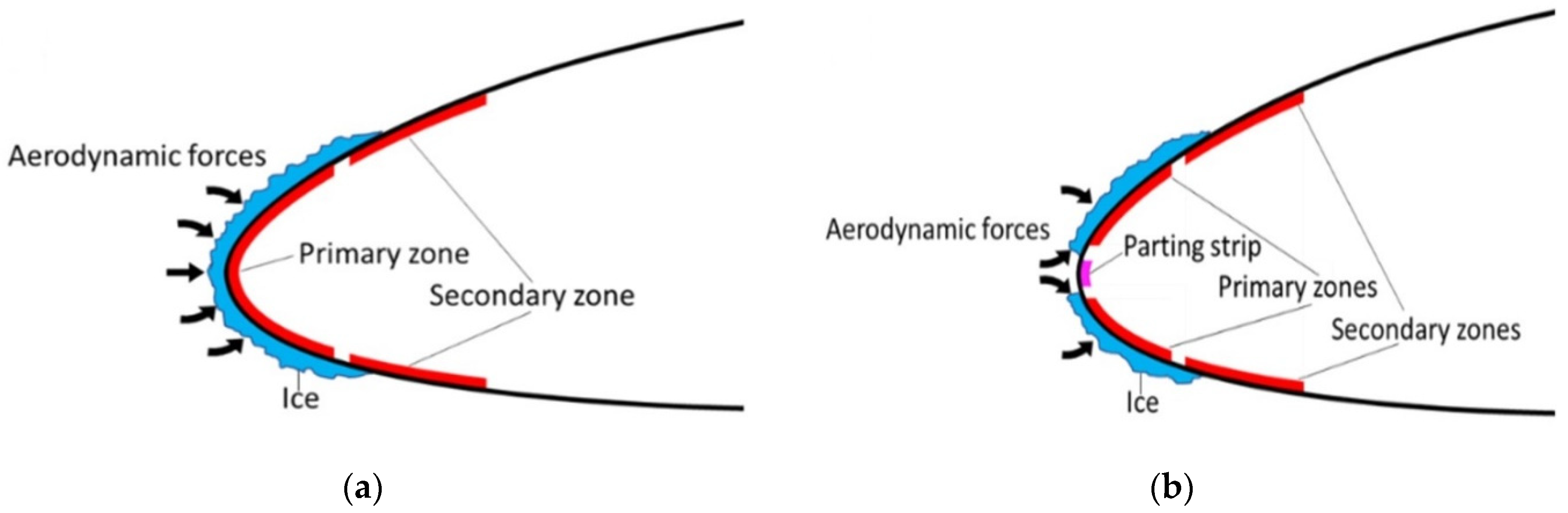
[120][50] tested the anti-icing, de-icing, and Parting Strip (PS) approach for ice mitigation on the same IPS in 2021. In the PS method, the stagnation zone at the leading edge is continuously heated to avoid ice formation, separating the ice on the upper and lower part of the airfoil. The ice split increases the aerodynamic force on the ice and allows for better shedding, as shown in
Figure 61. The parting strip model requires substantially less shedding time and heat flux than conventional techniques. Thus, the author considers the parting strip mode as the most energy-efficient ice mitigation mode.
Figure 61.
Conventional (
a
) and Parting Strip (
b) de-icing methods [120].
Superhydrophobic coatings can reduce the surface free energy and can generate hierarchical micro/nano-structured roughness. This can reduce the ice adhesion strength on the surface and thus prevent ice accumulation. Numerous studies related to different superhydrophobic coatings and the applicability of the same as an aircraft anti-icing material are done by Bhushan et al.
[121,122,123,124][51][52][53][54] and Farzaneh et al.
[23,125,126,127,128,129][55][56][57][58][59][60]. Ice accretion behavior of three different aluminum surfaces (hydrophilic, hydrophobic, and superhydrophobic) were compared by Wang in 2010
[130][61]. The research focuses on transmission line anti-icing; however, the findings can also be used for UAV ice mitigation. Initially, just a few portions of the superhydrophobic sample were coated with water droplets, whereas the hydrophobic was partially and the hydrophilic was entirely covered. Water droplets turned into the ice with increasing spraying time; however, no new ice crystals developed on superhydrophobic surfaces. Ice covered more of the hydrophobic surface and the whole of the hydrophilic surface with time. Thus, super hydrophobicity reduces surface wettability by increasing the average water contact angle to over
150∘. The same for hydrophobic surfaces of more than
90∘ and for hydrophilic surfaces, it is less than
70∘. Piscitelli
[131][62] in 2020 proposed a superhydrophobic coating for small aircraft that can reduce the surface free energy by 99% with respect to the reference considered in the study. Additionally, the proposed coating was effective at temperatures as low as −
27 ∘C.